Week 4-1D Element Creation Challenge
Skill-lync assignment (week 4)
Aim: The objective of this assignment is to mesh the given component with a target element length of 5 units after creating a representative mid-surface for it. This is to be followed by addition of masses and 1D elements of specified DOF & cross-sections that join the two parts of the components.
Case setup: The given component is a pair of metal brackets, as shown below.
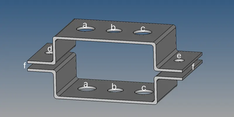 Figure 1: Bracket pairs
These parts are to be connected by the following types of 1 dimensional elements and masses at the specified points: -
- Rod element: Translational DOF constrained with RBE2 link. Box cross-section with a= 12 mm, b= 10 mm and thickness t= 0.75 mm.
- Beam element: All DOF constrained with RBE3 link. I cross-section with a= 8 mm, b= 10 mm, c= 8.5 mm, t1= 0.75 mm, t2= 0.6 mm and t3= 0.6 mm.
- Bar element: x & y DOF constrained with RBE3 link. X cross-section with DIM1= 5 mm, DIM2= 1.2 mm, DIM3= 10 mm and DIM4= 1.2 mm.
- Mass of 10 units with RBE2 link.
- Mass of 10 units with RBE2 link.
- Spring elements.
Procedure: The component is worked on through the following sequence of steps: -
- The component geometry is imported into the hyper-works workspace.
- The Geom>midsurface tab is used to generate the mid-surface for both parts of the component, as shown below.
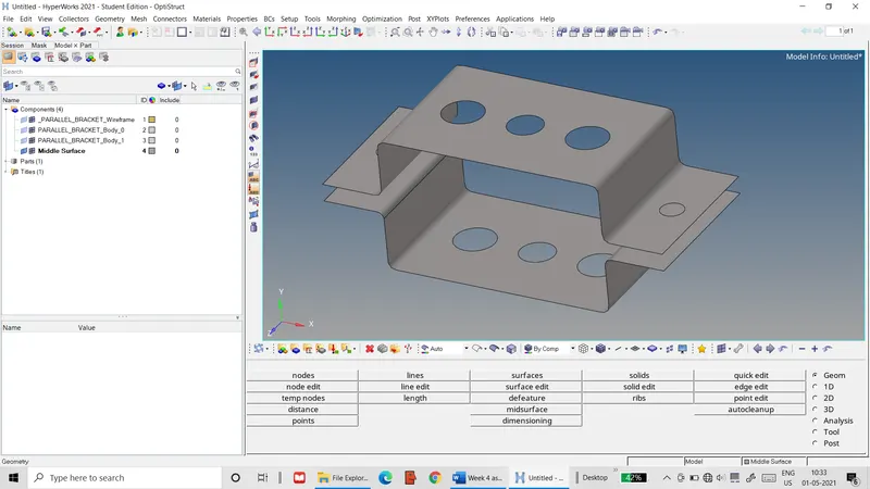 Figure 2: Mid-surface of brackets
- The Geom>quick edit tab is used to create washer regions 5 mm wide for all the holes of the surface, as shown below.
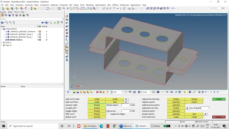 Figure 3: Washer surfaces for holes
- The 2D>automesh tab is used to mesh the mid-surfaces with a target element length of 5 mm. The washer regions are meshed first, followed by the rest of the mid-surfaces, as shown below.
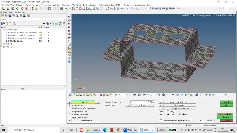 Figure 4: 2D shell mesh of brackets
- A new property with PSHELL element type is created and assigned to the bracket mesh.
- The 1D>rigids tab is used to define RBE2 links at the holes a, d & e with their respective DOFs constrained. The edges of the holes and their washer regions are used to define the slave nodes, while the master node is calculated to create the RBE2 links, one of which is shown below.
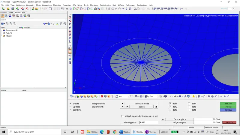 Figure 5: RBE2 link definition for one hole
- The 1D>rods tab is used to create a rod element at hole pair a. The CROD element type is assigned with the master nodes of the holes as the nodes of the rod element, as shown below.
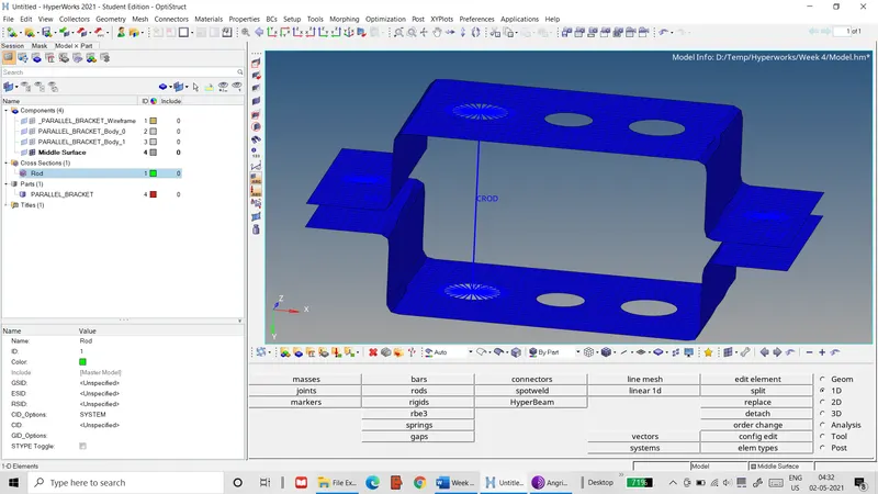 Figure 6: Rod element definition for hole pair a
- The 1D>HyperBeam>standard section is used to define a thin-walled box section for the rod element with the respective dimensions input.
- A new property for the rod element with PROD element type is defined, which is then assigned to the rod element. Similarly, a new MAT1 material card is defined that is assigned to the rod element.
- The 1D>rbe3 tag is used to define RBE3 links at the hole pairs b & c, with their respective DOFs constrained. As with the RBE2 links, the hole & washer edges are used to define the slave node, while the master node is calculated from these nodes.
- The 1D>bars tab is used to define a beam element with CBEAM element type in the hole pair b, in a similar manner to the rod element, as shown below.
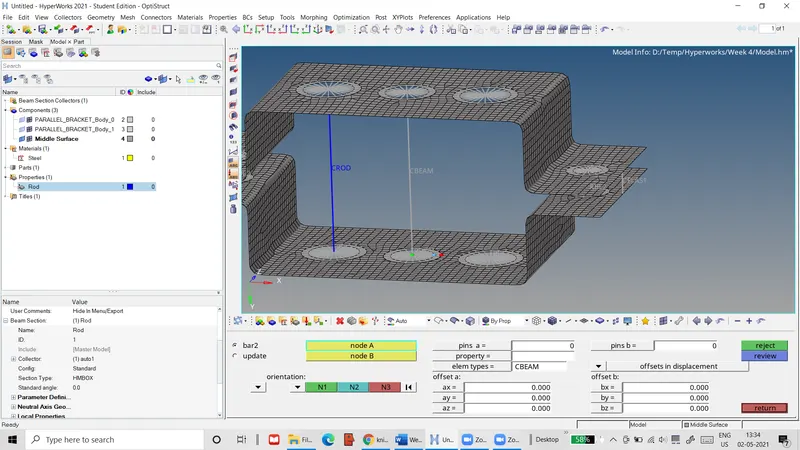 Figure 7: Beam element definition for hole pair b
- The 1D>HyperBeam>standard section tag is used to define an I-section for the beam element with the respective dimensions input.
- A new property with PBEAM element type is defined for the beam element, which is then assigned to it, along with the material.
- The 1D>bars tab is used to define a bar element with CBAR element type at the hole pair c, as shown below.
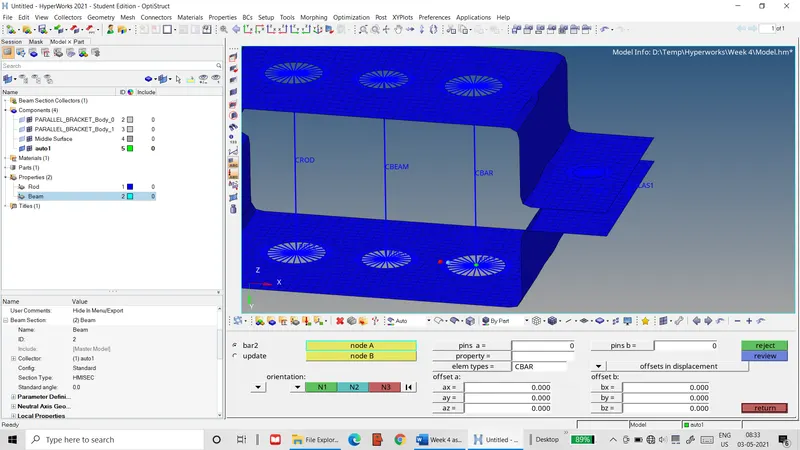 Figure 8: Bar element definition for hole pair c
- The 1D>HyperBeam>standard section tag is used to define an X-section for the bar element with its respective dimensions input.
- A new property with PBAR element type is define for the bar element and is assigned to it.
- The 1D>masses tab is used to add masses of 10 units with CMASS1 element type on the master nodes of the RBE2 links at the holes d & e.
- The 1D>springs tab is used to define spring elements at the ends f with element type CELAS1 and constrained to move in the translational y direction, as shown below.
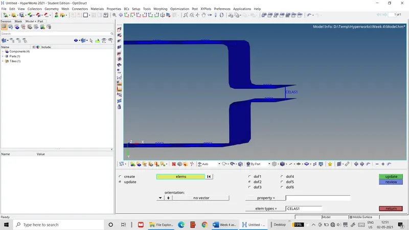 Figure 9: Spring definition at ends f
- A new property with PELAS element type is created and assigned to the spring elements, along with the material.
- The mid-surface and the mesh for each bracket are assigned to their respective bracket component using the Tool>organize tab. The original solid associated with the bracket components are then deleted.
- In a similar manner, separate components are created for the bar, rod, beam and spring elements, to which the respective elements are moved.
Result: The final, detailed mesh and associated 1D components are illustrated below.
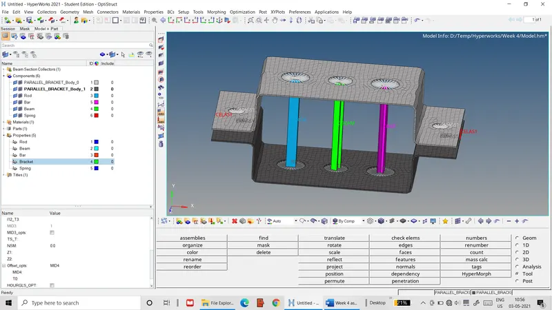 Figure 10: Final mesh with detailed representation