Week 12:Project 2-Meshing of Rear Wheel Holder challenge
Skill-lync Project 2
Aim: The objective of this assignment is to create a representative 2D mid-surface for the given component and generate a 2D shell mesh on this mid-surface that meets the specified element quality criteria.
Case setup: The given component is a rear wheel holder of a car trunk, as shown below.
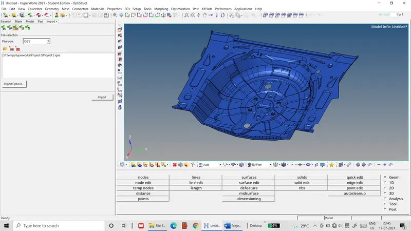 Figure 1: Rear wheel holder geometry
Its mid-surface is to be meshed with 2D shell elements with a target length of 5 units that meet the following element quality criteria.
Table 1: Element quality criteria
|
S.No. |
Quality Criteria |
Value |
|
1 |
Aspect Ratio |
5 |
|
2 |
Skewness |
45 |
|
3 |
Warping |
15 |
|
4 |
Taper |
0.5 |
|
5 |
Min. Length |
2 Units |
|
6 |
Max. Length |
8 Units |
|
7 |
Min angle Quad |
45 |
|
8 |
Max angle Quad |
135 |
|
9 |
Min angle Tria |
20 |
|
10 |
Max angle Tria |
120 |
|
10 |
Tria % |
10 |
Procedure: The component is worked on with the following sequence of steps.
- The geometry of the component is imported into the Hyper-works workspace.
- The geometry is checked for geometric errors and errors found are fixed using the quick edit tools, recreating missing surfaces and other relevant methods.
- The Geom>midsurface tab is used with the offset setting to automatically generate the mid-surface for the component. This mid-surface is then checked for geometric errors like the main component and the found errors are rectified.
- In order to ensure mesh quality, the mid-surface is defeatured by toggling off edges that would result in small elements, relocating corners between edges etc. This operation includes removing the button areas shown below from the mid-surface due to their small size that would negatively affect the mesh quality.
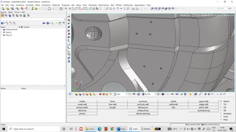 Figure 2: Buttons removed from the mid-surface
- The element quality criteria are input in the criteria file settings.
- The mid-surface is then meshed section-by-section using the 2D>automesh tab. The mesh is refined and cleared of elements failing the quality criteria by a combination of the quick edit tools, smoothing operations, replacing nodes and remeshing problematic areas.
- In order to reduce the time & effort needed, some symmetrical regions have one side meshed and the resultant elements are reflected to the other side using the Tool>reflect tab.
- After meshing the entire mid-surface, the Tool>edges tab is used to check for free edges within the mesh that would indicate unconnected nodes. The edges found are eliminated with the equivalence option. Nodes that cannot be connected by this option are connected using the replace tool.
- A new material card and a property card are defined with the thickness of the component (0.75 units) being assigned to the property card. These cards are then assigned to the mid-surface.
Result: The final mesh for the component’s mid-surface is illustrated below.
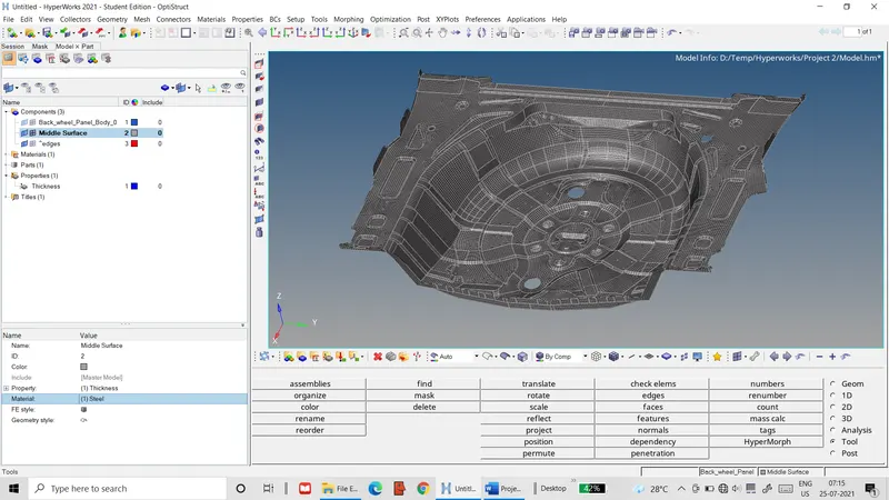 Figure 3: Final FE mesh of wheel holder mid-surface