Radar Mast & Final Assembly of Yacht
CAD modelling & assembly of predator yatch using Solidworks
Aim: The objective of this project is to use Solidworks 3D CAD to create detailed 3D models of the various components of a predator yatch and use these models to create a full assembly of said yatch. The assembly model is then to have its images rendered with suitable camera angles and background.
Introduction: Solidworks is the standard software package that is used to create 3D CAD models for any geometric part or component. The model files generated by Solidworks are used for a variety of other operations like FEA analysis, manufacturing specifications, creating presentable images of conceptual designs before prototyping etc.
Solidworks 3D CAD is being used here to generate such model & assembly files for a predator yatch. The necessary models will be generated by making use of as many of the available tools as possible. Part models will be created for each individual component. These models will then be assembled together in a single assembly file. Finally, the complete assembly will have highly detailed images rendered, which will be compiled in this report.
Design methodology: The models & images are generated in a series of steps, as illustrated by the flowchart below.
- First, a series of sketch images are assembled together in a single part file, as shown in the image below.
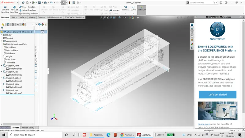 Figure 1: Blueprint part with sketch arrangements
The sketch images show various orthographic views of the intended yatch model. This part file, called the blueprint part, is used as the foundational basis for roughly modelling all the individual parts of the yatch.

- For each part, a copy of the blueprint part is opened and all the part’s sketches & features are built with the visual aid of the blueprint part’s sketch images. The parts are built with various combinations of 2D & 3D sketches, extruded & revolved features, projected curves, lofted surfaces, cuts and fillets & chamfers. These parts are also assigned colours and surface decals.
- For some parts, like the yatch hull and the superstructure, certain surfaces are duplicated and isolated as separate surface bodies. These surface bodies serve as additional references for the other parts, whose dimensions & features are based on these surfaces. These surface bodies are imported along with the blueprint part for the other parts.
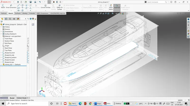 Figure 2: Blueprint part with deck surface reference imported from hull part
- Once all the parts are fully modelled, an assembly file is created into which the individual part files are imported. Here, the parts are combined together with suitable concentric/coincident mates that are appropriate for each part pair.
- After the yatch model has been fully assembled, the Solidworks photoview 360 add-in is activated. The model is then positioned and assigned suitable lights, cameras and background and the model image is finally rendered using photoview 360. Multiple images of the yatch are rendered with different combinations of lights, camera angles and rendering options.
Resultant part files: A total of 9 different part files were created for the yatch assembly, which have all been catalogued below. It is to be noted that since the yatch model is being built for display purposes, many of its components like the anchor are combined together into common part models.
- Hull:
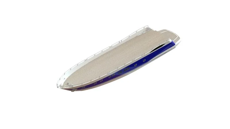 Figure 3: Isometric view of hull with deck surface decals
- This part was the largest of all the parts with the greatest number of features used for modelling.
- The hull was modelled using nearly all the modelling tools available in Solidworks, including extrudes, cuts, surfaces, projected curves, patterns, mirrors etc.
- The deck was given the appearance of teak wood panels by applying decals of wood panel images on the deck’s upper surface.
- The deck surface of the hull was duplicated into a separate surface body so that it could be used as additional reference for other parts.
- Radar:
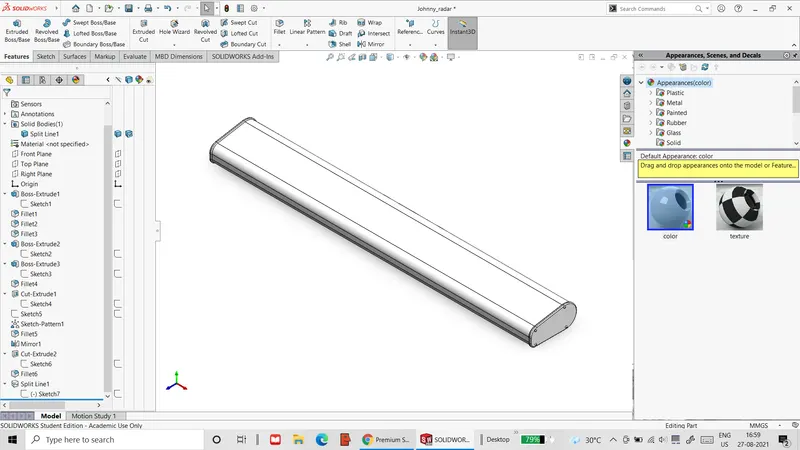 Figure 4: Part file of radar
- This is geometrically the simplest of all the parts to model.
- The radar is created using straight extrudes & cuts.
- Propeller:
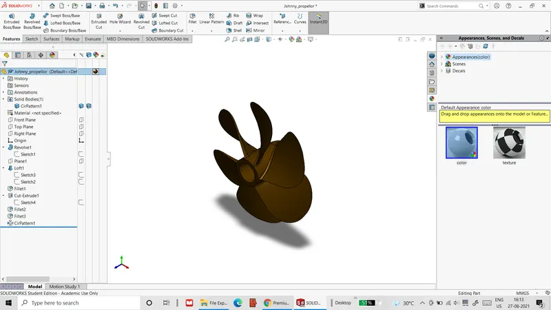 Figure 5: Part file of propeller
- This part is another one of the geometrically simple parts.
- It is made with a combination of revolved & lofted extrudes.
- Garage door:
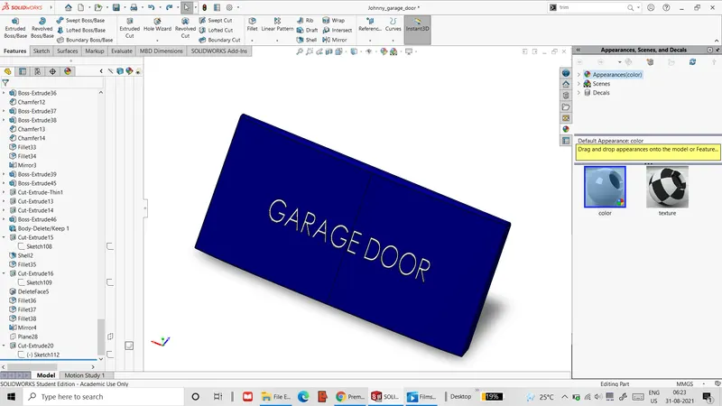 Figure 6: Part file of garage door
- This part is created from the hull part. First, a section of the hull’s solid body is separated from the rear region with the help of extrude cuts and the resultant solid body is saved as a separate part file.
- This part is then shaped into the garage door part with the use of extrude cuts, fillets and shell transformations.
- Rear seat:
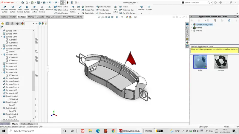 Figure 7: Part file of rear seat
- The seat geometry is based on the deck surface reference defined in the hull part.
- The seat is made by creating extruded & lofted surfaces that are stitched together to form a solid body.
- The flag at the rear of the seat is created as a lofted surface between 4 3D curves.
- Middle seat:
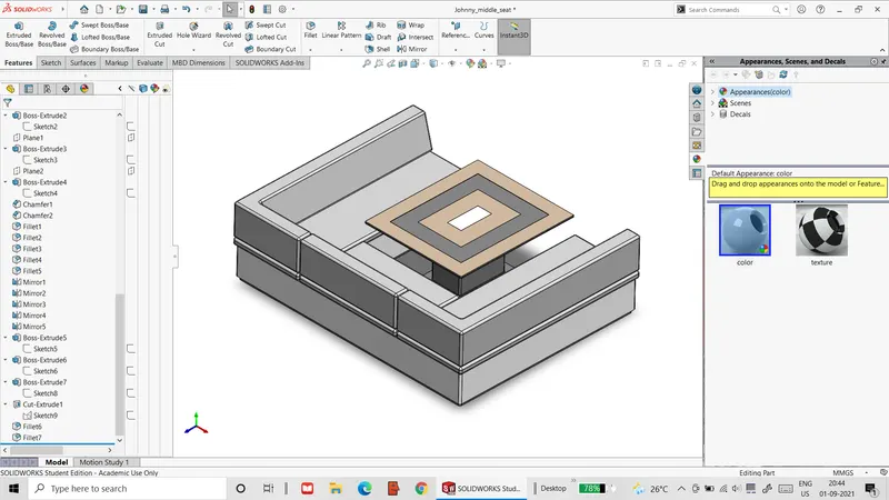 Figure 8: Part file of middle seat
- Like with the rear seat, the middle seat’s geometry is based on the deck surface reference.
- The seat is made by extruding sketches defined on the reference surface.
- Front seat:
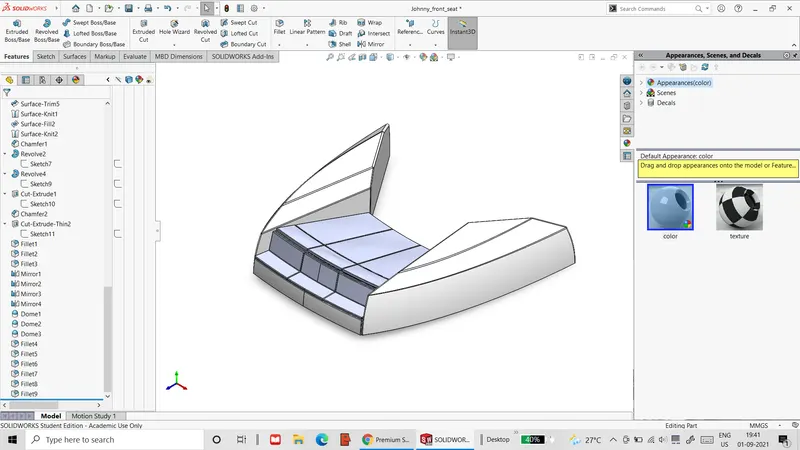 Figure 9: Part file of front seat
- The front seat is also based on the deck surface reference.
- The seat is made with a combination of extrudes & revolves and stitched surfaces.
- Superstructure:
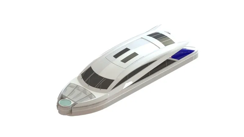 Figure 10: Part file of superstructure
- While this part does not have as many features as the hull, it is the most geometrically complex.
- The superstructure is created by a number of projected curves that are used to make several lofted surfaces. These surfaces are then knitted together to form the solid body.
- Additionally, a surface on the top is duplicated to form a new reference surface for the radar mast part.
- Radar mast:
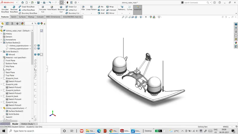 Figure 11: Part file of radar mast
- The part is based on the reference surface defined in the superstructure part.
- The part is created with extrudes, revolves, cuts, swept features and mirrors.
Final rendered images of assembly: The images of the final assembly are compiled below.
- The following are the contour render of the yatch assembly and the feature tree of the same.
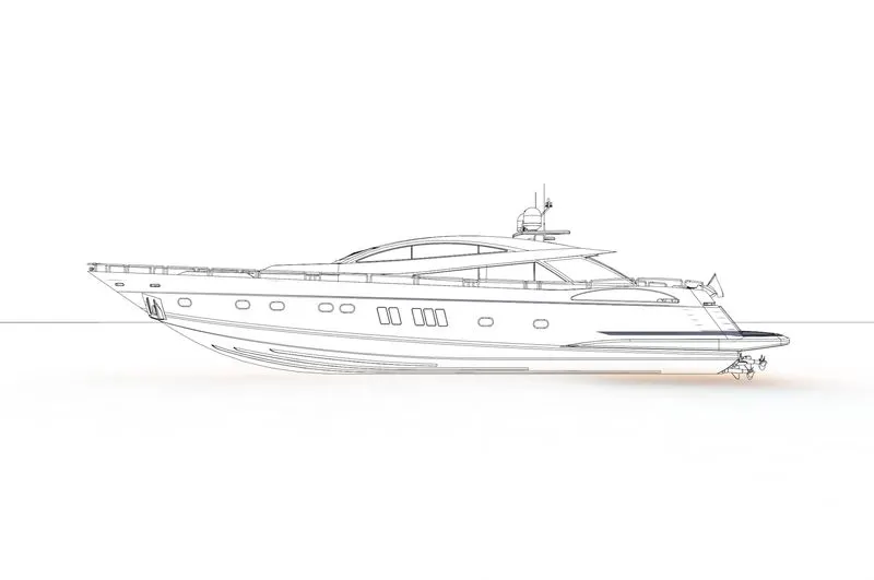 Figure 12: Contour render of yatch assembly
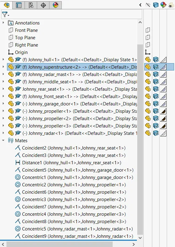
Figure 13: Expanded feature tree of yatch assembly
The contour render is well suited for use as a sketch in a manual.
- The following images show the front, side, back and top view of the yatch assembly.
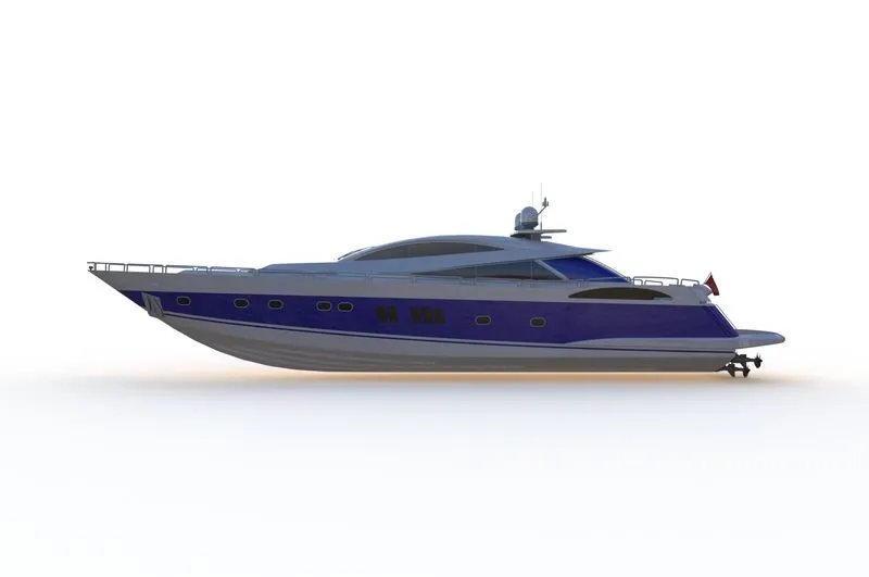 Figure 14: Side view of yatch assembly
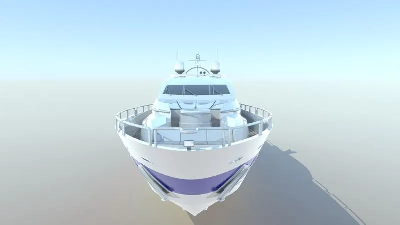 Figure 15: Front view of yatch assembly
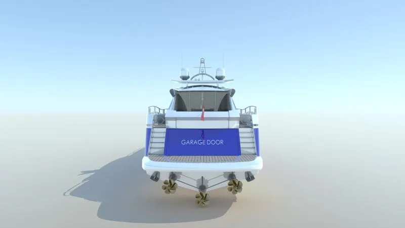 Figure 16: Back view of yatch assembly
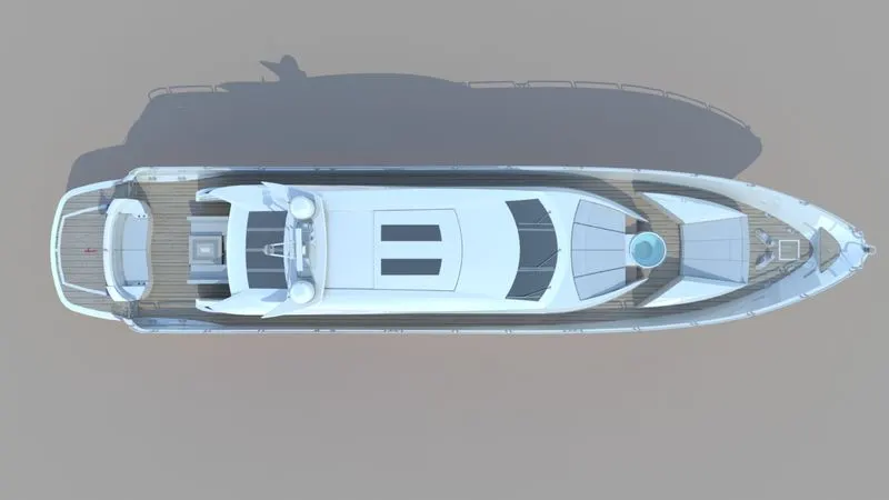 Figure 17: Top view of yatch assembly
They show the geometric details of the assembly as well as the decals that give the appearance of wood panels.
- The following images show the yatch assembly presented as if it were in the open sea.
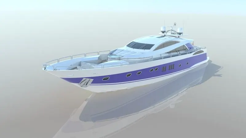 Figure 18: Rendered image of floating yatch
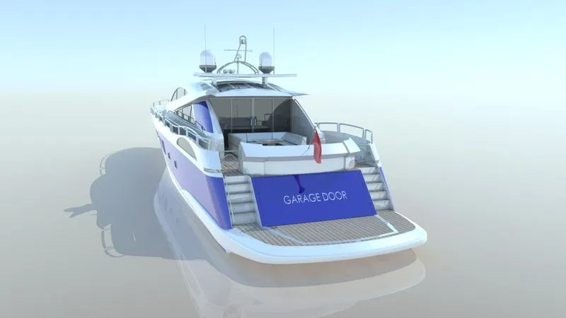 Figure 19: Rendered image of floating yatch as seen from the rear
The appearance of the yatch floating in water is achieved by providing a floor offset of 2 meters above the yatch’s lowest point, and including floor reflections.
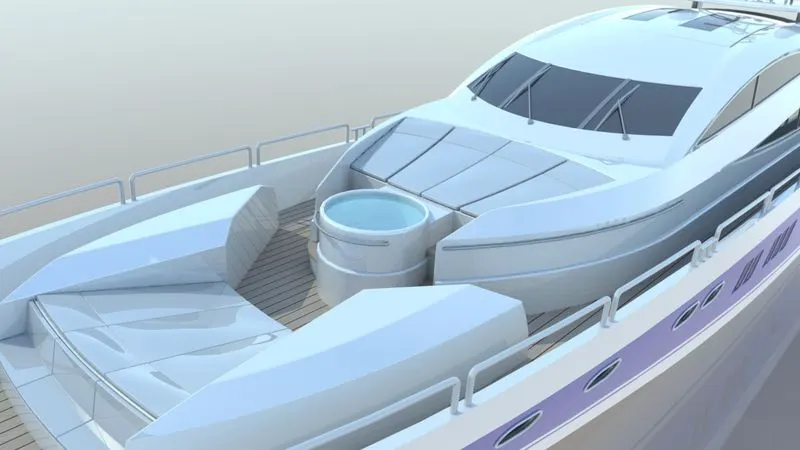 Figure 20: Rendered image of jacuzzi region
The water in the jacuzzi is modelled as a blue surface with a fairly high transparency. While the bottom of the jacuzzi can be seen through the water from the top view, the water surface is reflective when seen from the angle shown above.
Conclusion: The predator yatch has been fully modelled as a complete assembly. It has also been presented in a believable manner through a series of detailed image renders.