Week 3 - External flow simulation over an Ahmed body.
1. Title – Simulation of Airflow around Ahmed Body
2. Objective –
- To make 3d model of Ahmed Body and mesh it.
- To solve the model and calculate coefficient of drag and coefficient of lift.
- To generate pressure, velocity contour and vector plot.
- To perform grid independency test.
3. Introduction –
Computational fluid dynamics is a branch of fluid mechanics in which fluid slow is analysed using numerical methods. There are many types of CFD software available in the market and Ansys fluent is one of them. CFD simulations is an efficient tool in automatic industry used extensively for design. This allows the designers to obtain a quick and proper analysis before go ahead to the final step. CFD analysis in car industry is used in the determination of the applied forces and that of the vehicles wake during moving. CFD also is used to analyse the effect of wake on the vehicle’s efficiency and capability in comparison with other cars.
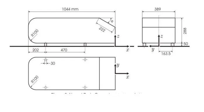
In this study we will perform simulation on Ahmed body. Ahmed Car Body is the standard model that can be used as validating case, in industry and CFD simulation Ahmed Body is a generic car-type bluff body with a slant back has different angles from 0 – 40 degree.
4. Theory –
One major area of study in the automotive industry is the study of air flow over a car and its resultant drag and lift forces. High drag force will cause a reduction in fuel efficiency and a vehicles top speed, whilst lift can positively or negatively affect tire traction depending on whether it is in an upwards or downwards direction. (Costa, B 2015) Accurate measuring of the drag and lift forces computationally in turn depends on accurate modelling of turbulent flow, thus there is a need verify the accuracy of current turbulence models in an automotive context. The accurate modelling of turbulence has always been a considerable challenge for engineers throughout history. This fluctuating nature of turbulence makes a deterministic approach very difficult, so most current methods of solving turbulence related problems and modelling tend to be more approximating in nature.
A great deal of studies regarding airflow and turbulence behaviour on a car involve the use of the Ahmed body, which was first devised by S, Ahmed in 1984. He said referred Ahmed body as a strong three-dimensional displacement flow in front, relatively uniform flow in the middle and a large structured wake at the rear. It has had a significant impact on research in the automotive industry, used to study and validate flow over an automotive in both wind tunnel and CFD environments. In the case of CFD its simple shape reduces required computational power and time taken to model the body and run simulations.
Ahmedian body(original)
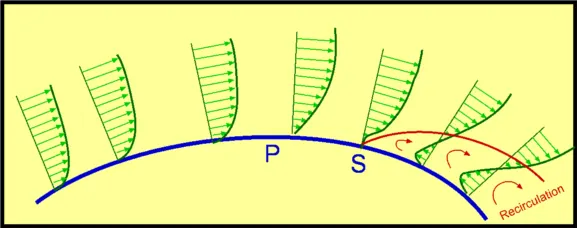
Point of separation and its significance – Flow separation is position where the boundary layer leaves the surface of the body in other words it is region where wall shear stress is zero.
Point of separation totally depends in the type of geometry. Pressure gradient is one the factor which effects fluid flow. Change in kinetic energy is directly linked to a change in static pressure according to Bernoulli principle. In this case, the increase in kinetic energy is at the expense of the pressure (energy). The static pressure thus decreases to a minimum up to the thickest point of the cylinder. The pressure gradient in x-direction is negative in this area.
Now the effective cross-section of the flow increases, as the cylinder cross-section decreases flow slows down and the static pressure rises again in the x-direction to finally reach the level of the atmosphere This pressure gradient acting against the actual direction of flow is called adverse pressure gradient and it is positive. Depending on the shape of the body, the resulting adverse pressure gradient can become very large due to the decrease in speed and the boundary layer thickness increases significantly. this will lead into a flow separation.
Point of separation plays significant role in real world phenomenon specially in aerodynamics, where flow separation results in reduced lift and increase in drag and it causes buffeting of aircraft structure.
Flow separation phenomenon -
Negative pressure in wake region –
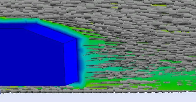
In the case of the cylinder, after separation region the adverse pressure gradient even becomes so large that the flow is forced back against the actual flow direction. This results in a backflow area and the laminar flow detaches itself from the contour at this point. A so-called turbulent wake is formed behind the body. Stress become negative here and this results into a negative pressure gradient.
5. Procedure –
Three are three main step of any simulation first is pre-processing, which includes geometry setup, cleaning and mesh generation. Second step is solving the model and third one is post-processing which includes plotting, contour generation and analysis. In the study we proceeded with following procedure and data values.
Geometry setup –
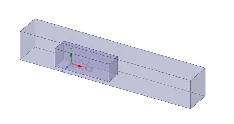
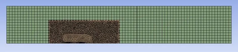
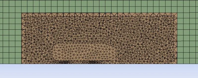
Double encloser is used to generate different mesh different areas.
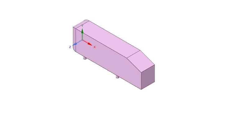
Ahmed body model(halved) -
Model with enclosers -
Meshing –
Mesh was generated for three different cases, so cases will only be differ in element size.
Generated mesh -
Closer look -
|
Case/mesh parameters |
Case1 |
Case2 |
Case3 |
|
Element Size |
0.1 |
0.115 |
0.130 |
|
Body element size |
0.05 |
0.07 |
0.09 |
|
Face element size |
0.01 |
0.01 |
0.01 |
|
Number of elements |
104950 |
51594 |
29381 |
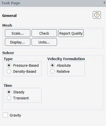
Solver setup –
Solver type –
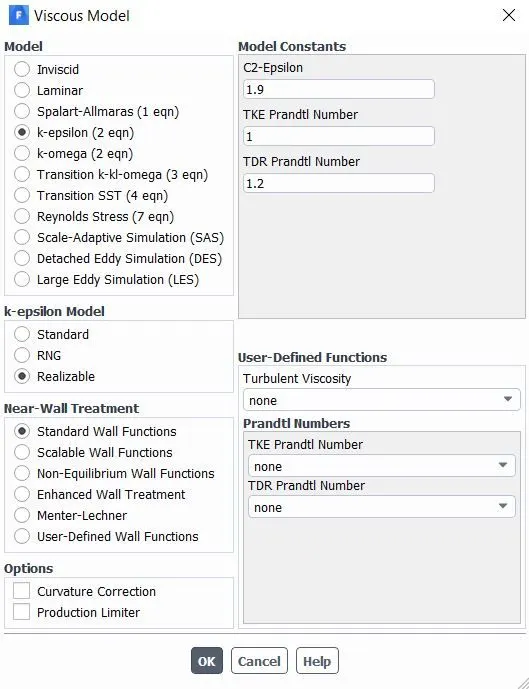
Solver Model –
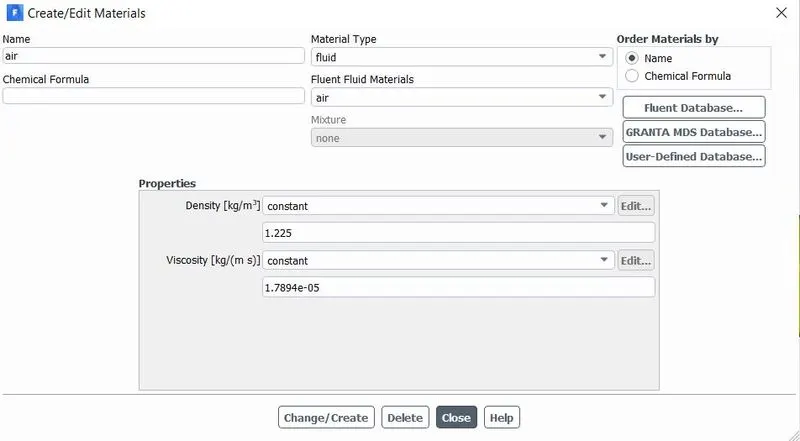
Material used –
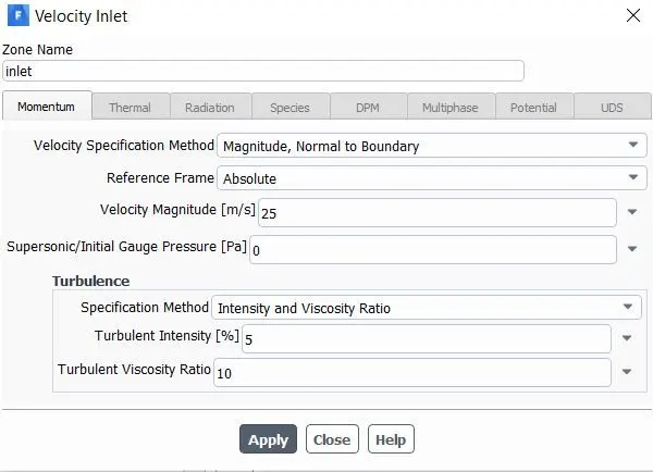
Boundary condition -
Results –
Case1 –
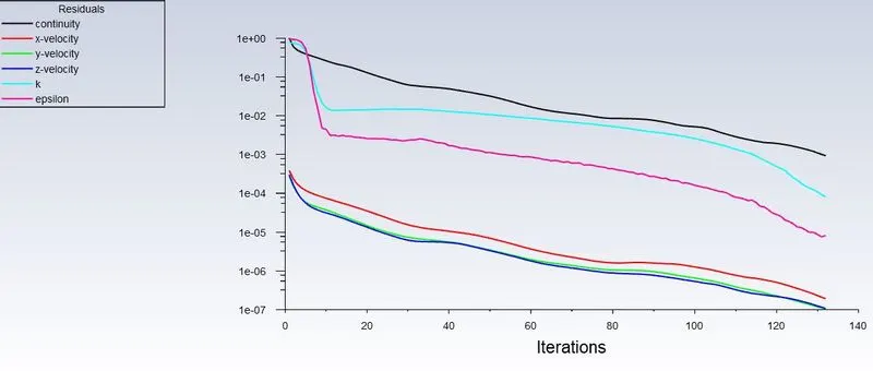
Residuals -
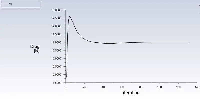
Drag -
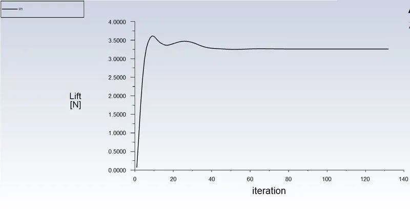
Lift -
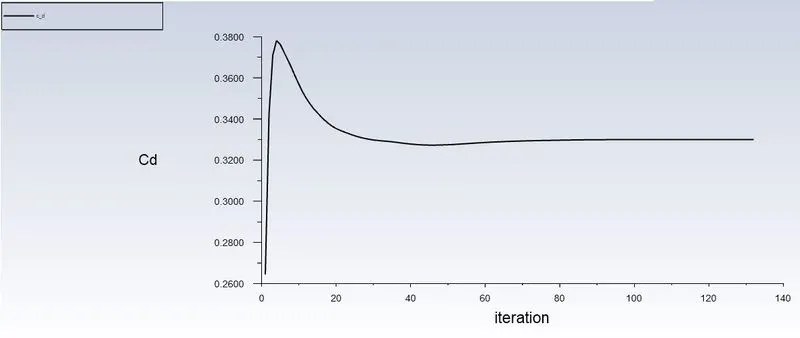
Coefficient of Drag –
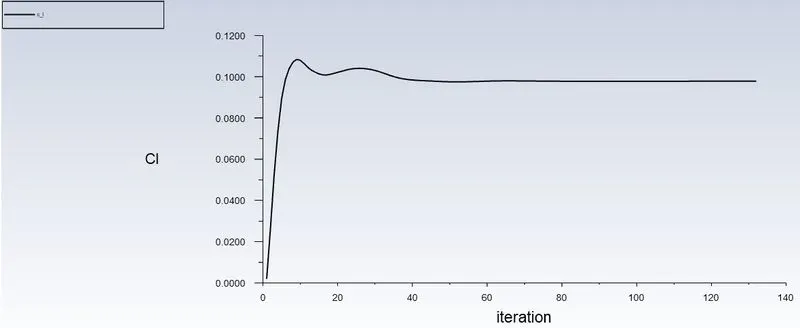
Coefficient of Lift -
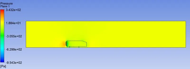
Pressure contour –
Velocity contour –
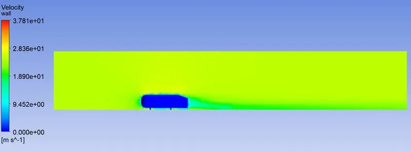
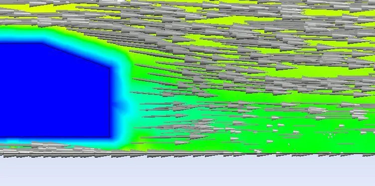
Velocity Vectors -
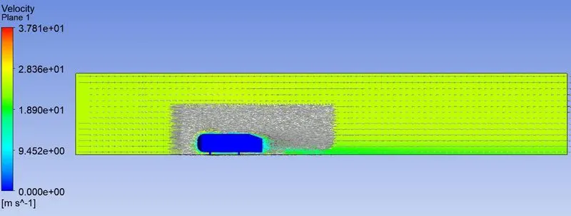
a closer look
Case2 –
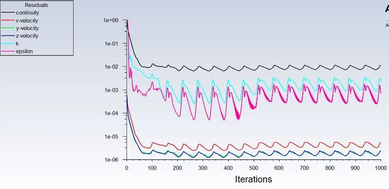
Residuals -
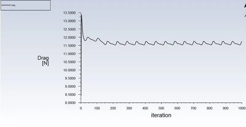
Drag -
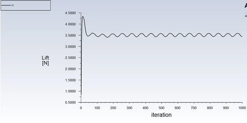
Lift -
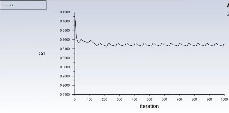
Coefficient of Drag –
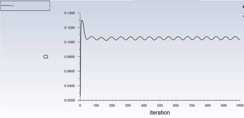
Coefficient of Lift -
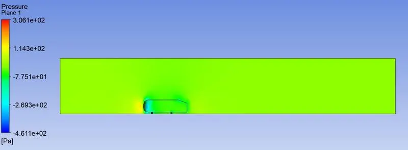
Pressure contour –
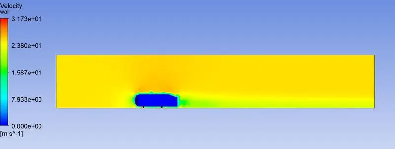
Velocity contour –
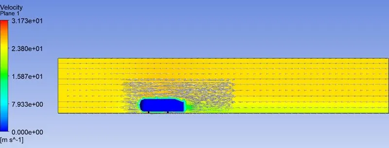
Velocity Vectors -
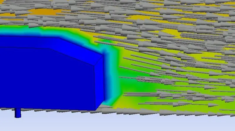
a closer look -
Case3 –
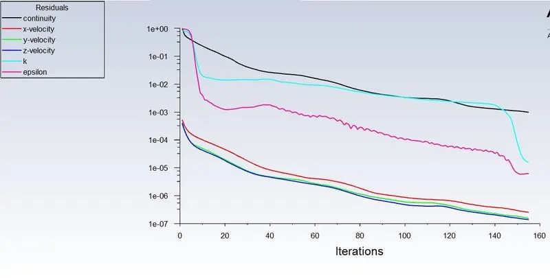
Residuals -
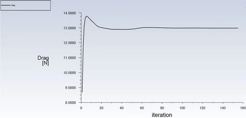
Drag -
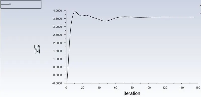
Lift -
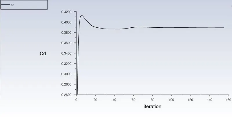
Coefficient of Drag –
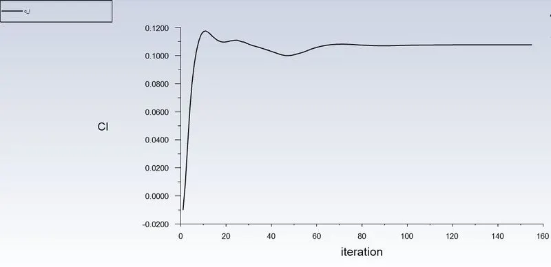
Coefficient of Lift -
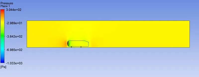
Pressure contour –
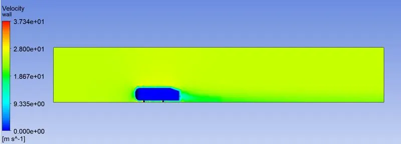
Velocity contour –
Velocity Vectors -
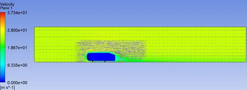
a closer look -
|
Case/Inferences |
Case1 |
Case2 |
Case3 |
|
Number of iterations |
133(Converged) |
1000 |
155(Converged) |
|
Drag Coefficient |
0.3345 |
0.3447 |
0.3890 |
|
Lift Coefficient |
0.0977 |
0.1009 |
0.1077 |
|
Drag |
11.0058 |
11.625 |
12.9752 |
|
Lift |
3.2612 | 3.5000 | 3.5919 |
6. Conclusion –
We simulated flow over Ahmed body to find out drag coefficient, drag and lift and conducted grid independency test also. As mesh gets finer, simulation defines wake region better. We used three different meshes to simulate flow over the car and we can infer from that finest mesh is complying with numerical results, we got drag coefficient 0.33 at air velocity 25m/s with decent residual values. This case is recommended for further simulations. Drag and lift is also decreasing with mesh refinement.