Week 4 - CHT Analysis on Exhaust port
1. Title – CHT Analysis on Exhaust Port Manifold.
2. Objective –
- To import CAD model of exhaust port and extract volume for fluid flow.
- To mesh model with suitable size and inflation layers.
- To solve conjugate heat transfer with suitable solver and boundary conditions.
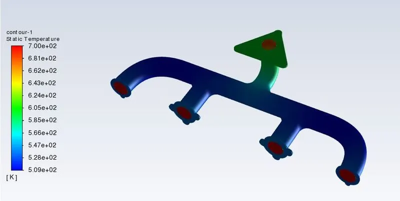
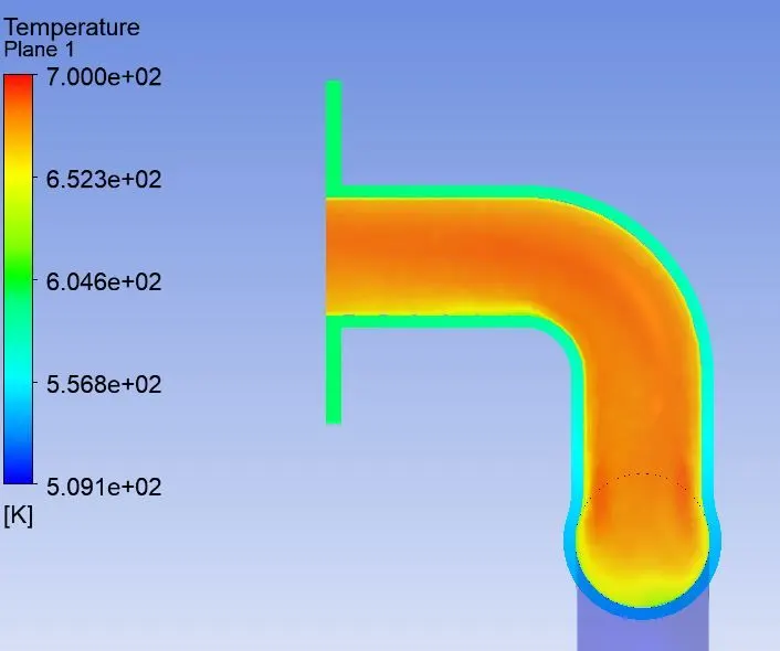
- To generate contour plots for static temperature, fluid velocity and heat transfer coefficient and analyse it.
3. Introduction –
Computational fluid dynamics is a branch of fluid mechanics, which uses mathematics, physics and computational software to visualize how fluid flows and affects its medium and its neighbours. In CFD mostly computers are used to predict the fluid flow phenomena based on some governing equations like conservation of momentum – Navier stokes equation, conservation of energy etc. In this study we are going to simulating CHT using Ansys fluent software.
Conjugate heat transfer (CHT) – this is analysis which allows the heat transfer between fluid and solid by energy interaction. CHT analysis can accurately predict heat transfer by simultaneous solving all the relevant solid and flow field heat transfer processes.
4. Theory –
Heat transfer properties prediction is very important in many engineering applications. Ansys fluent is leader in solving heat transfer model. It is very important to understand physics first, like radiation model predicts heat transfer between non-contact bodies. Similarly, CHT analysis predicts heat transfer properties where heat interaction is between solid body and fluid. CHT has many applications like simulation of cooling of electronic component, simulation of heat exchangers. In the real-world phenomenon mostly three modes of heat transfer acts together, that why it is necessary to study CHT.
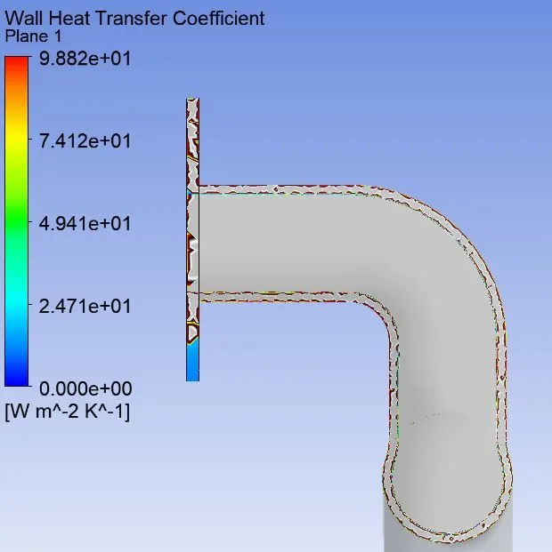
Heat transfer coefficient is a factor which tell us, how well heat is transferred. In our study heat is transferred from hot air to manifold, heat transfer coefficient is predicting how easily heat is transferred here. There are many factors which affects heat transfer coefficient like – properties of fluid, geometry, flow type, velocity of fluid flow etc. we can have an eye on these factors during simulation and can tell about prediction accuracy.
5. Procedure –
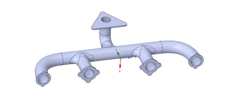
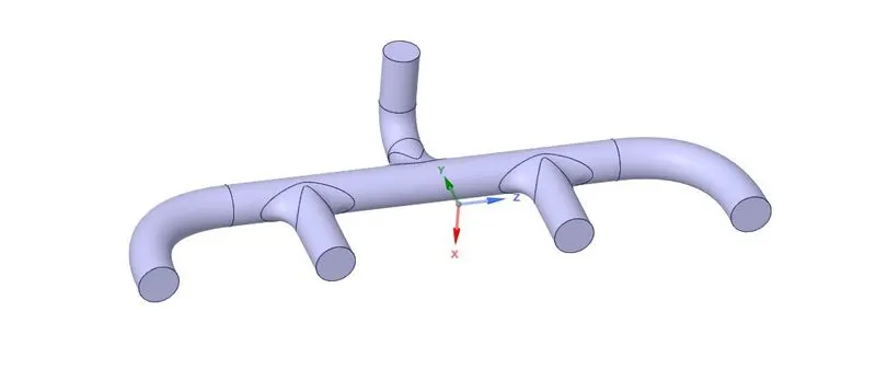
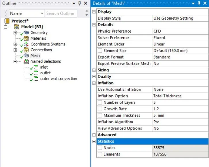
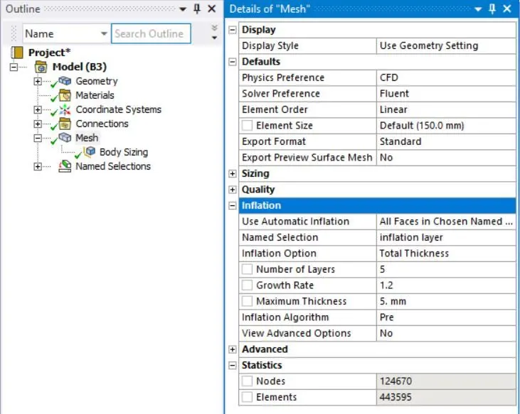
In this study we are going to analyse heat interaction between exhaust manifold and fluid flowing in it. For this we will use two different meshes and generate temperature contours also. Other setting is going to same. The following procedure is followed to analyse CHT on exhaust manifold.
Geometry –
Solid -
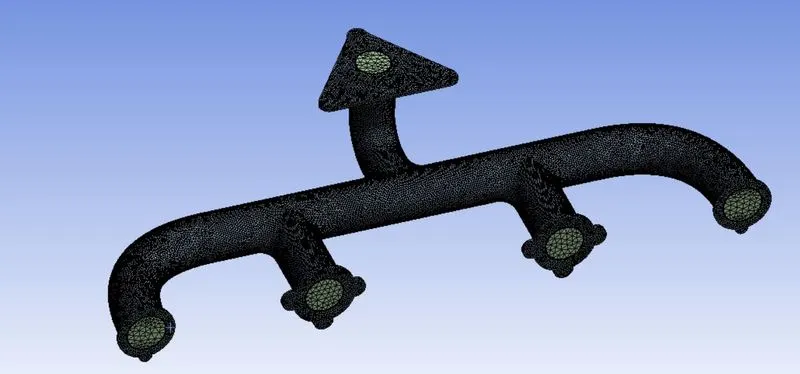
Extracted volume -
Mesh generation –
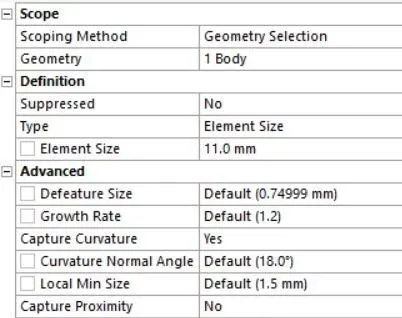
Mesh setting- Case 1
Mesh setting- Case 2
Body sizing
Solver setup –
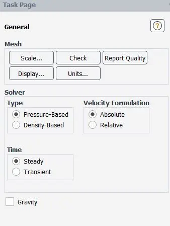
General -
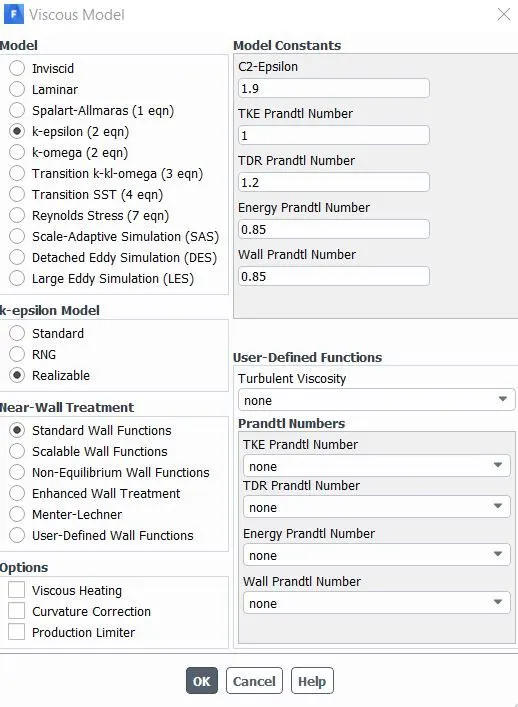
Solver Model -
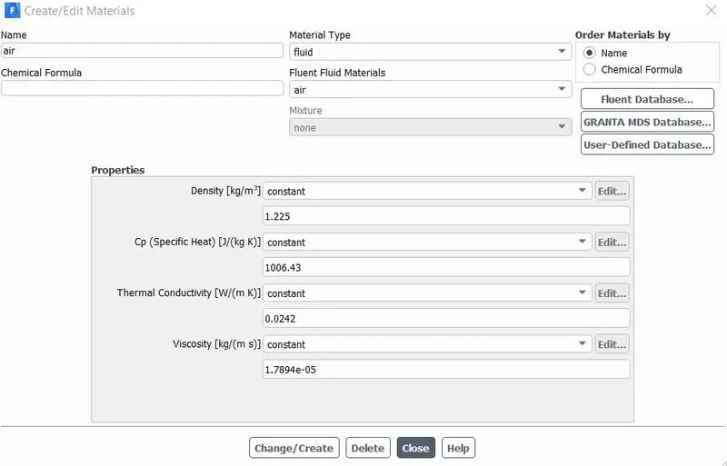
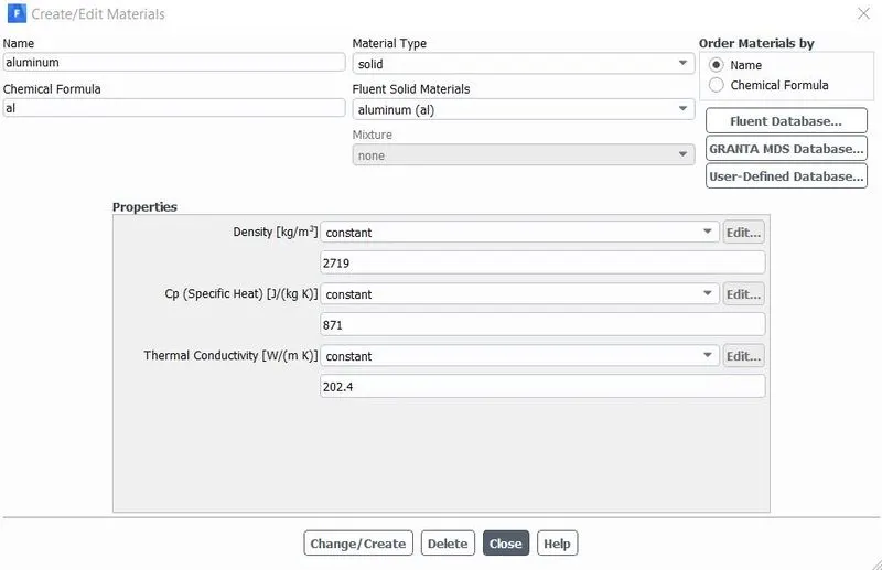
Material Setting -
Boundary conditions -
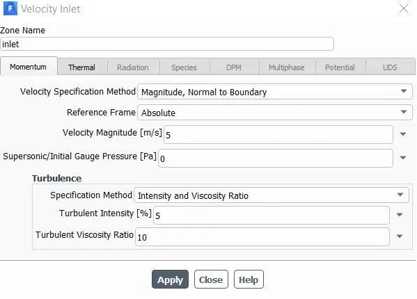
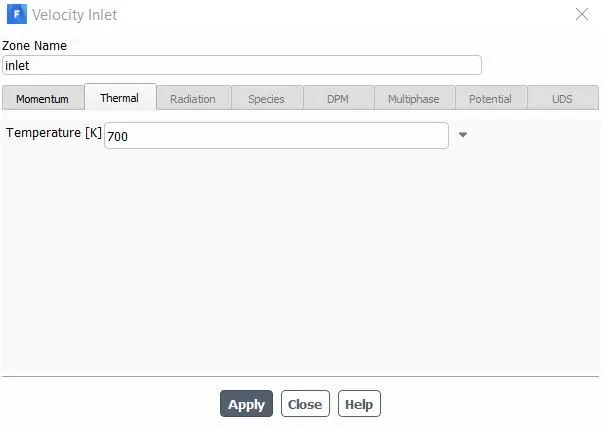
Inlet -
Results -
Case1 -
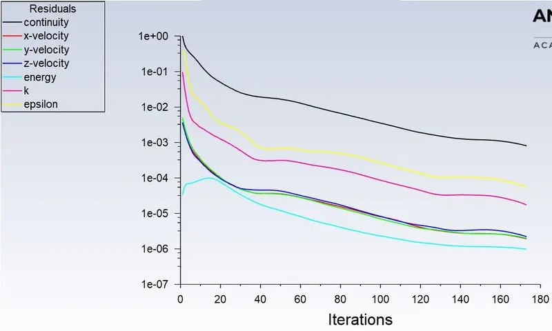
Residuals -
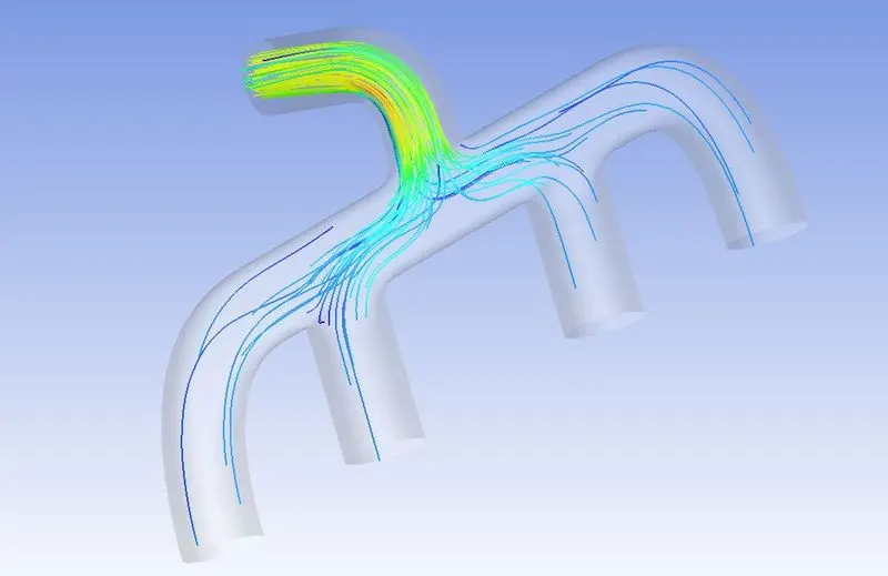
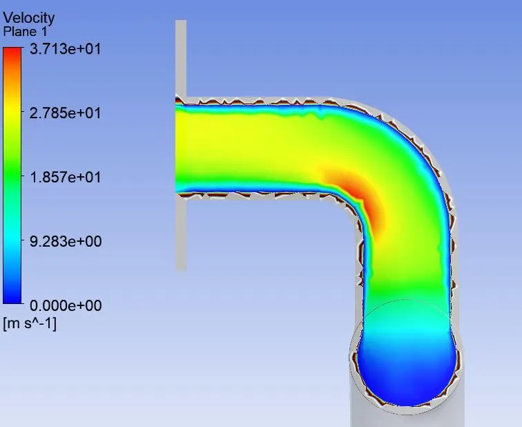
Velocity Contour -
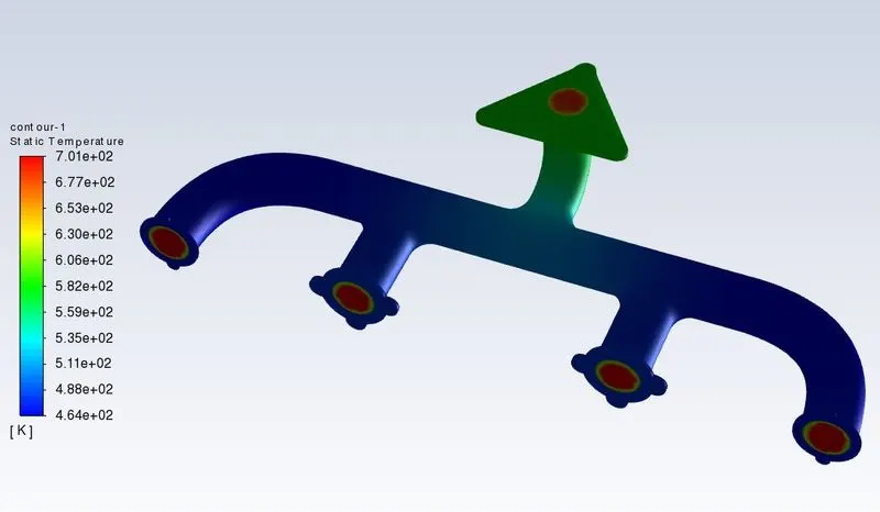
Temperature Contour -
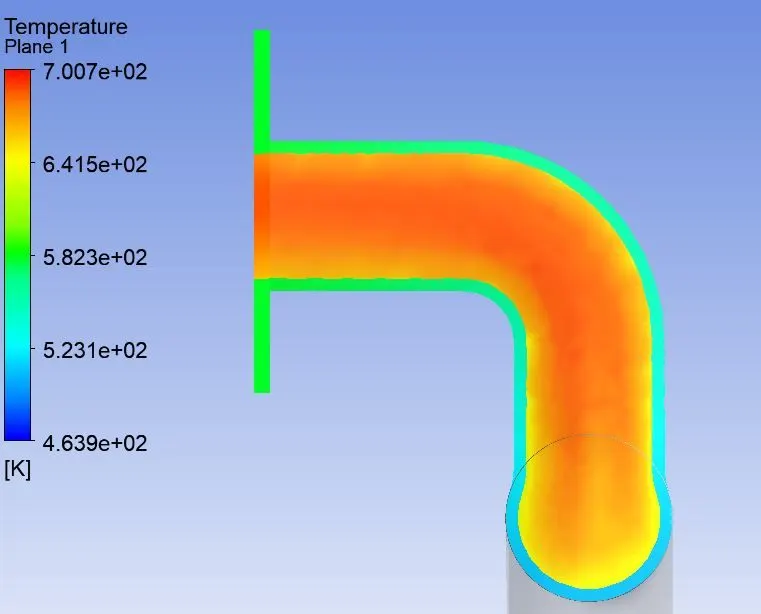
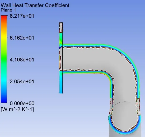
Heat Transfer Coefficient -
Case2 -
Residuals -
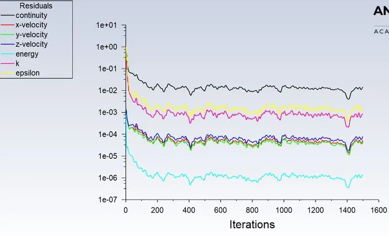
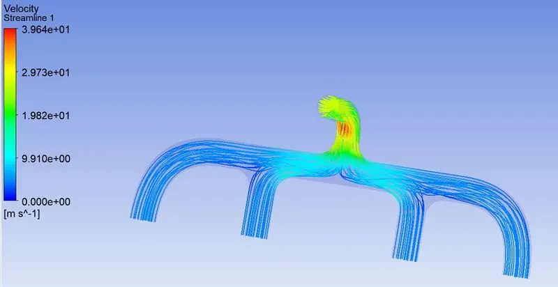
Velocity Contour -
Temperature Contour -
Heat Transfer Coefficient -
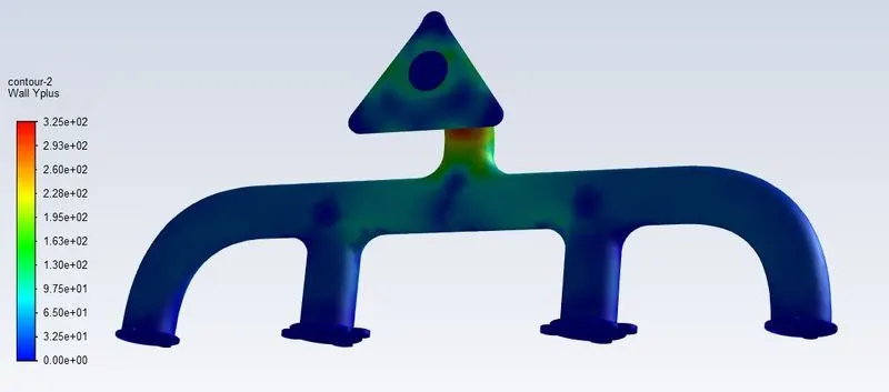
Y plus is non dimensional region which is used to distinguish fluid flow layer. Y plus is also used to find thickness of first layer near the wall. For this study we got following wall y plus values -
From k epsilon model -
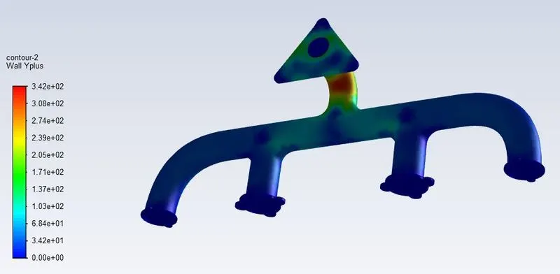
From k omega model -
6. Conclusion –
Conjugate heat analysis can accurately predict heat transfer by simultaneous solving all the relevant solid and fluid field heat transfer process like free and forced convection in gases, in IC engine analysis, conduction through etc. in this study CHT analysis has done to find out temperature rise manifold because of hot air passing through it and we predicted heat transfer coefficient as well. Velocity contours were crated to get insights of fluid path and maximum velocity area. It can be seen from graph that heat transfer coefficient is related to wall only. Simulation is conducted two different mesh distinguished in size. The simulation can be performed for a wider range of base mesh size values.