Week 9: Project 1 - Surface preparation and Boundary Flagging (PFI)
1. Title - Surface preparation and Boundary Flagging.
2. Objective –
- Import the CAD model of IC engine into converge and run diagnosis.
- Look for errors and solve them, without compromising actual model.
- Setup the case for no hydrodynamic simulation, solve it and create animation in Paraview to see valve and piston movements.
3. Introduction –
Surface preparation and boundary flagging is important steps before we go case setup. These terms are related to converge software only, in CFD domain we can call surface preparation as geometry clean-up. In simple language, surface preparation is process to detect the error in CAD model and solve the them, if one goes negligence, he will definitely end simulation with wrong results. Boundary flagging is a procedure in which we assign the suitable names to the boundaries, because CFD software does not have intelligence to do the same.
4. Theory –
Surface preparation and boundary flagging are major step to begin any simulation, one has to be very careful about these steps, otherwise it will ruin the simulation. In this section we will see the major types of error and their diagnosis, specific to converge software only. Converge automatically highlights the errors by magenta colour, after error check, but have to look at the reason behind the errors then only we can remove them.
Intersections – As the name suggest that intersection of the plane of one triangle to another plane of triangles. Areas and angles less than specified values will be also considered as intersection error. Intersection error can be removed by translating or rotating the surfaces or increasing the angle or areas, if any.
Nonmanifold Problems – Nonmanifold Problems arises when an edge that is shared by more than two triangles or A vertex that connects two otherwise disconnected pieces of geometry. This is error will be removed automatically after assigning the boundaries or regions.
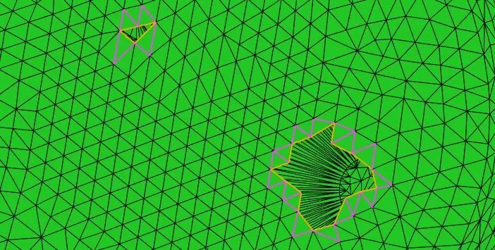
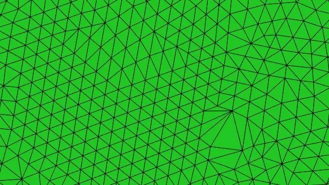
Open Edges – this problem arises when there is an open edge, since converge works on the volume so its does not allow open edges. Make patch or stitch triangles to remove this error.
Overlapping triangles -Triangles that meet other triangles at an angle less than the specified value, in degrees. Delete the overlapping triangle and make patch if necessary.
Normal orientation – this problem arises a triangle have different orientation of normal than its adjacent one. This error can be removed easily by translating the normal.
5. Procedure –
Converge provides a simulation type called as no hydro simulation, this option allows us to see the grid and its movement if is dynamic, so after simulation, we can assure our self that simulation is running without any error, after it we can to full hydrodynamic where fluid and its movement, properties will come into the picture. In this study we performed no hydrodynamic simulation on IC engine model, to see the piston and valve movement, for that following procedure was followed –
1. Import the CAD model and go to diagnosis menu and check for the errors.
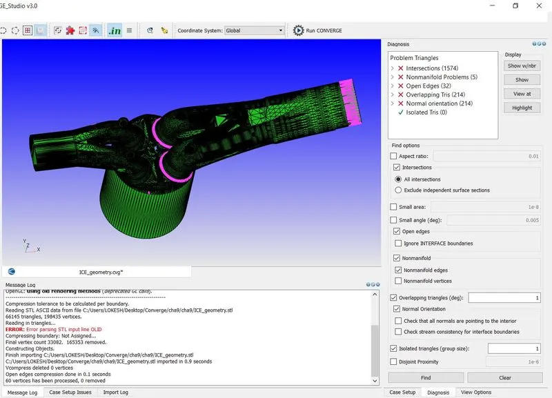
2. Converge will throw the error when there are non-manifold problems, overlapped triangles, intersections, open edges etc. one can use option from display to locate the errors, which is beside to errors.
3. We went for boundary flagging first and then solved the errors, because boundary flagging allows us to hide specific part of model, we can see inside the model and again it will ease our error detection.
4. The following images is showing the boundaries, we used fencing option multiple time for demarcation.
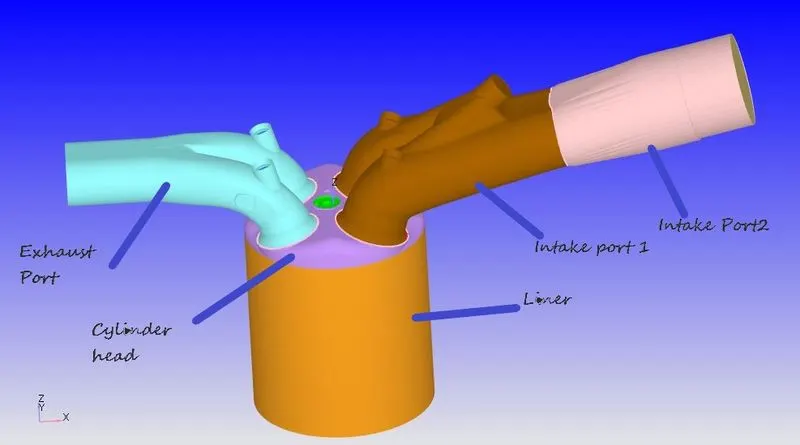
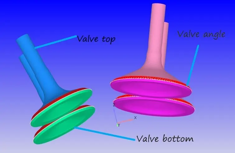
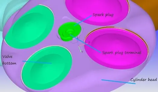
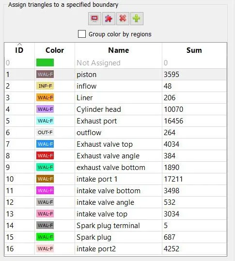
5. After boundary flagging it was easy to visualize some hidden parts. Errors were removed as discussed in theory section.
Open edges - patches were created to solve this problem. Repair>Patch>Free edge loop
Before -
After -
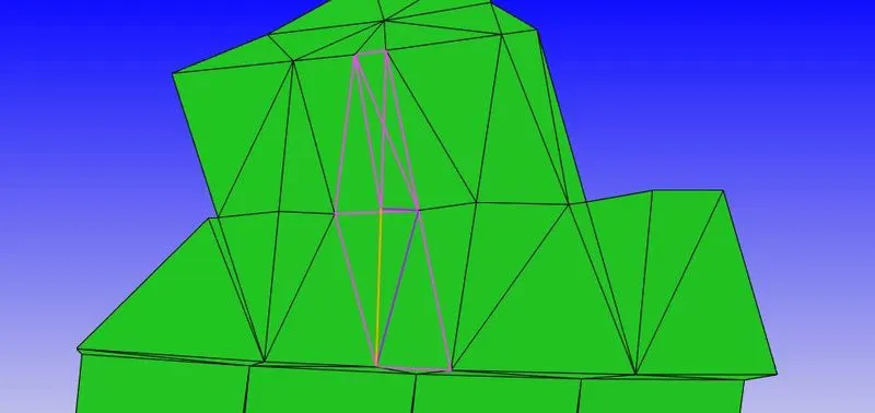
Non-manifold problems - Extra triangles deleted first and then patches were created.
Before -
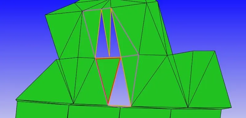
After -
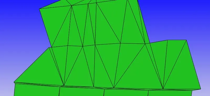
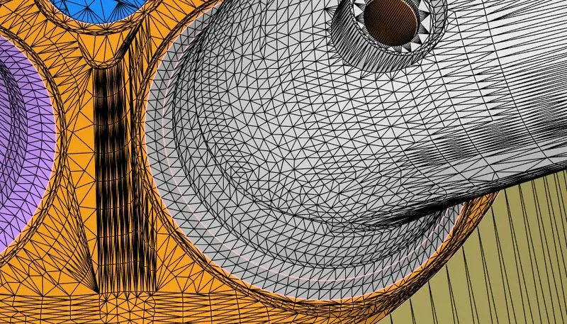
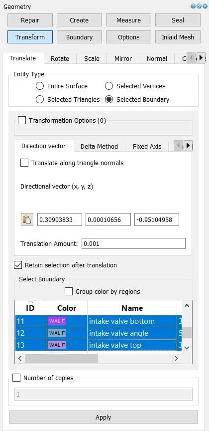
Intersections - inlet valve moved in its normal direction with 1mm distance to solve this problem. Transform>Translate>Selected Boundary
Before -
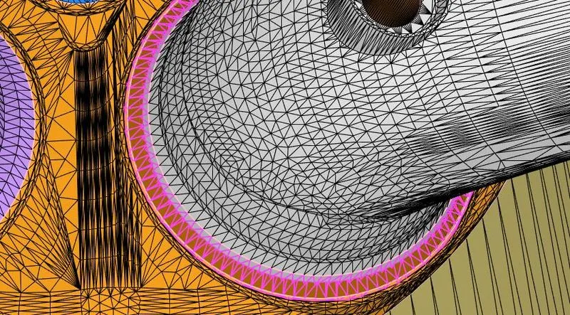
After -
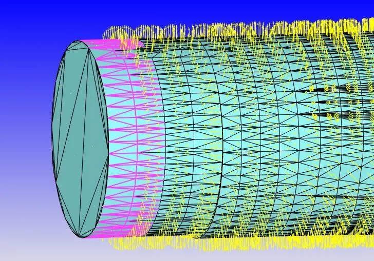
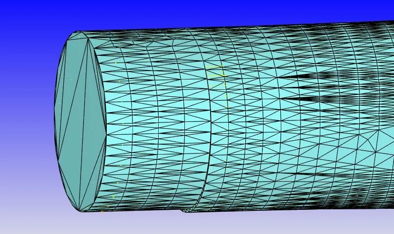
Normal orientation - normals were transformed inward. Transform>Normal
Before -
After -
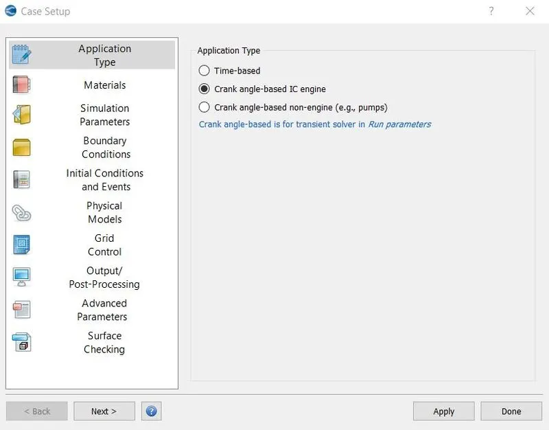
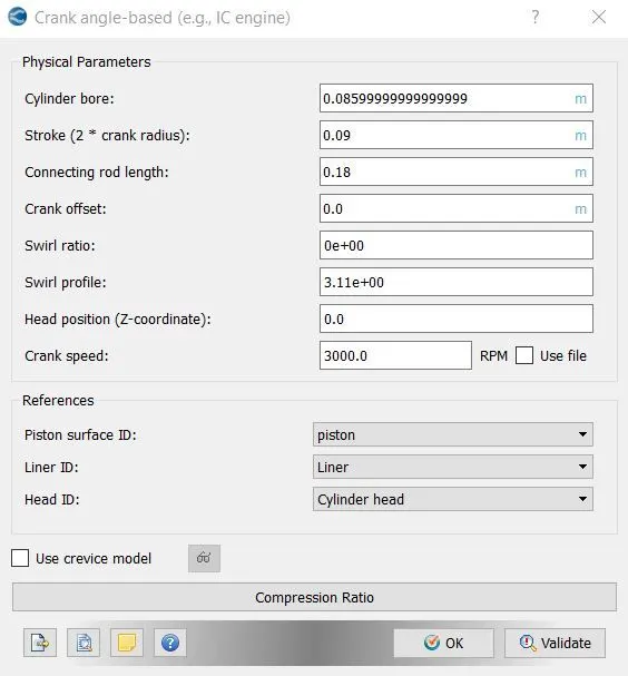
6. In the case setup we started with crank angles-based IC engine as application type. In crank angle-based menu some parameters were defined as shown in the following image.
7. In gas simulation parameter therm.dat file was imported which contains gas thermodynamic data specifically related to IC engine.
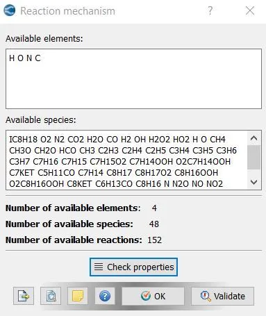
8. In reaction mechanism windows properties were checked to see the available species, which were imported by therm.dat file.
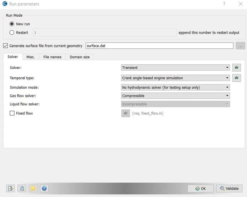
9. In run parameter transient was chosen as solver type with no hydrodynamic simulation mode, because we wanted to see mesh movement only without the effect of fluid.
10. In simulation time parameter start and end time were specified in degrees.
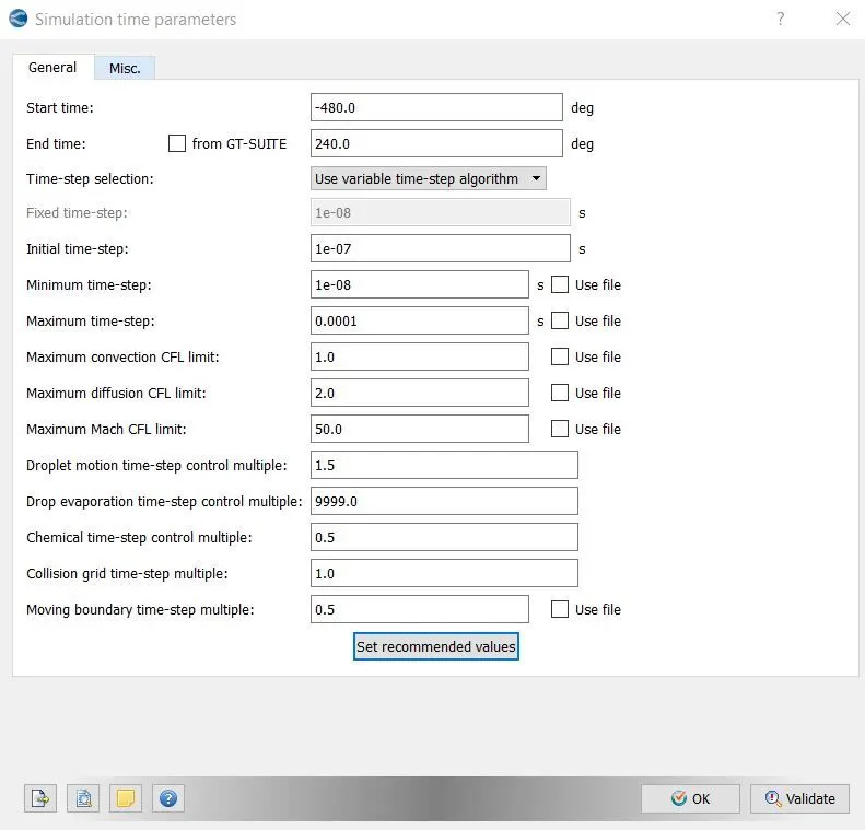
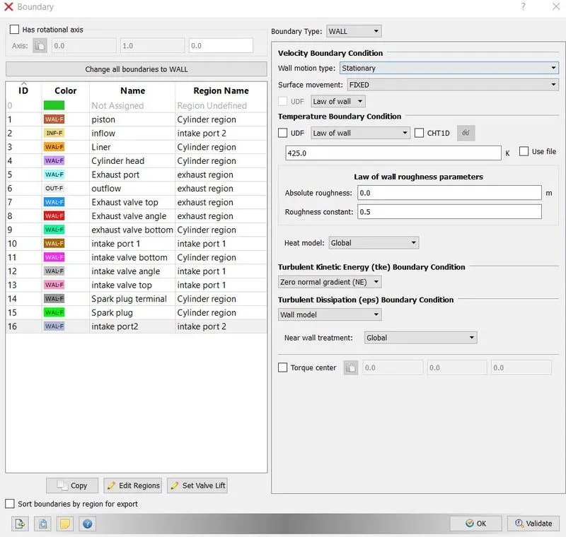
11. There were 16 boundaries created in flagging process. Boundary conditions were given as the following images –
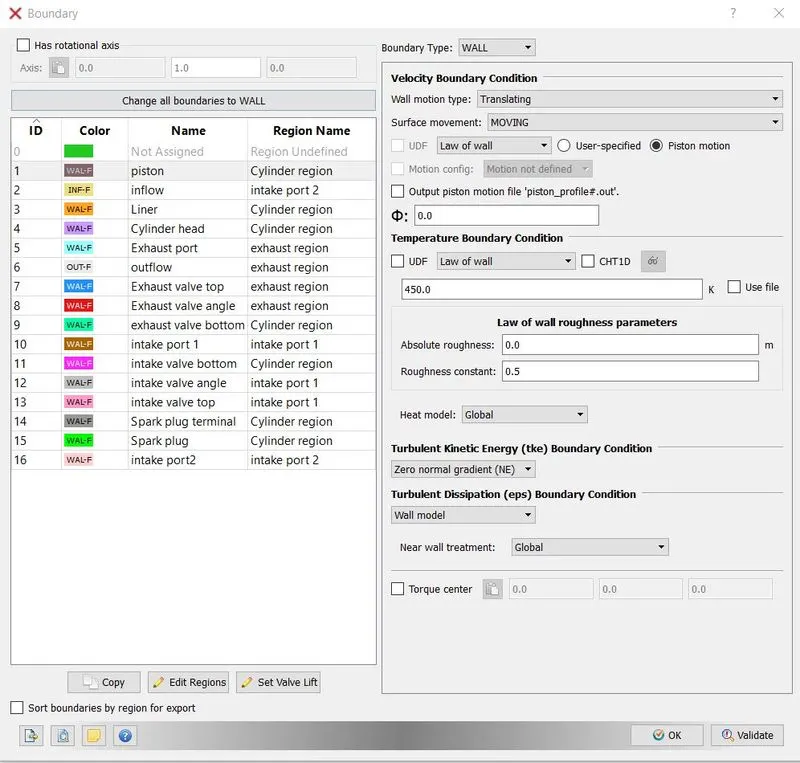
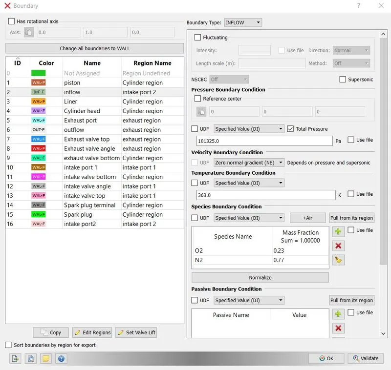
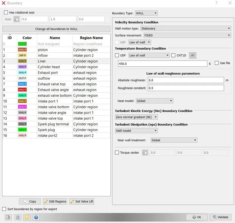
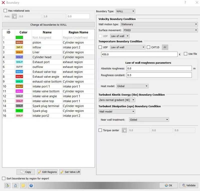
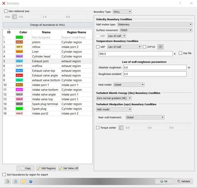
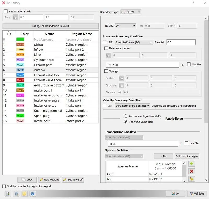
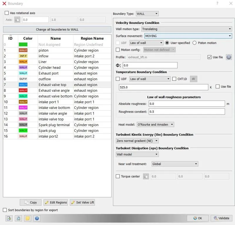
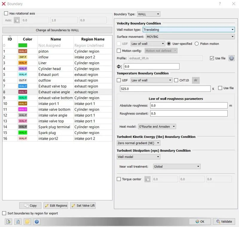
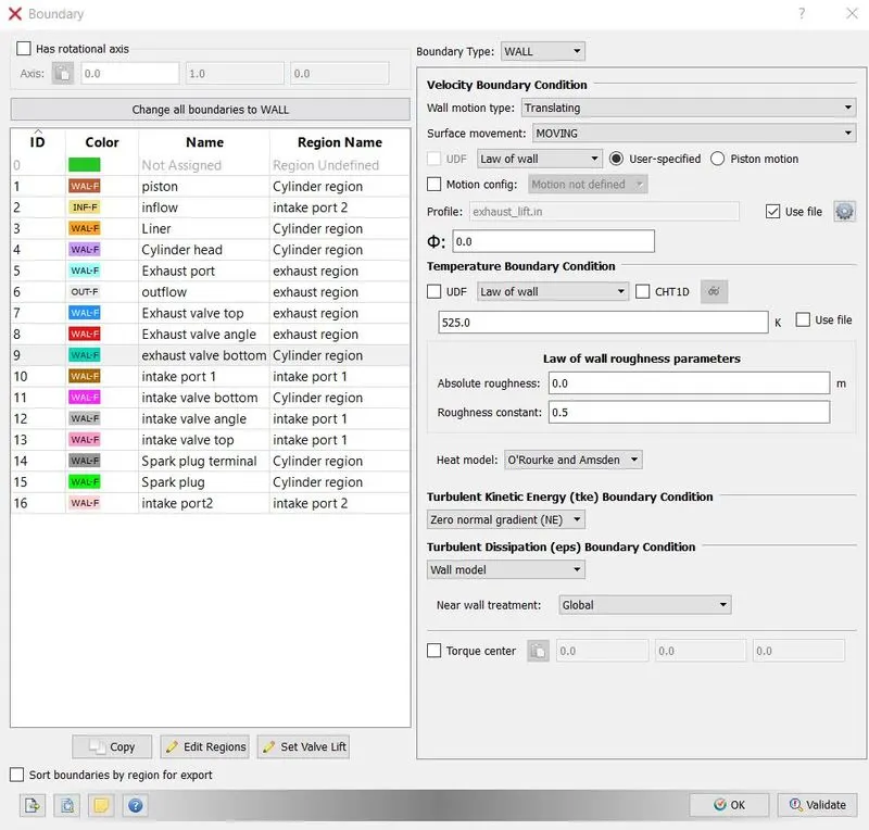
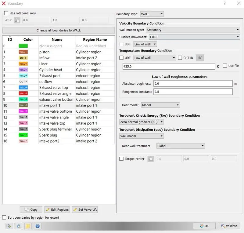
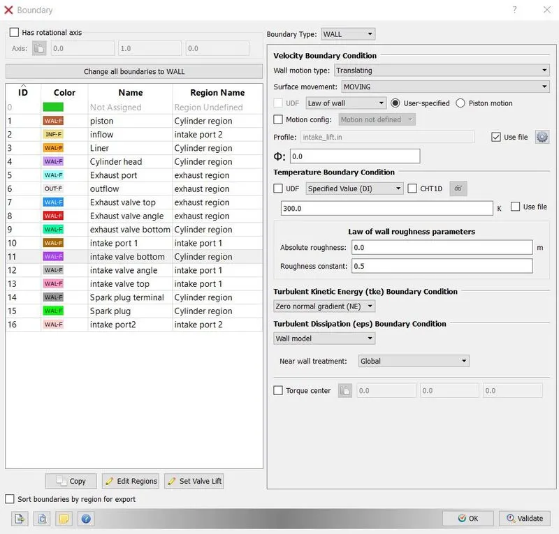
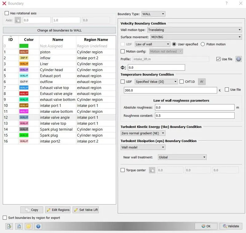
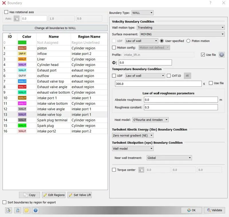
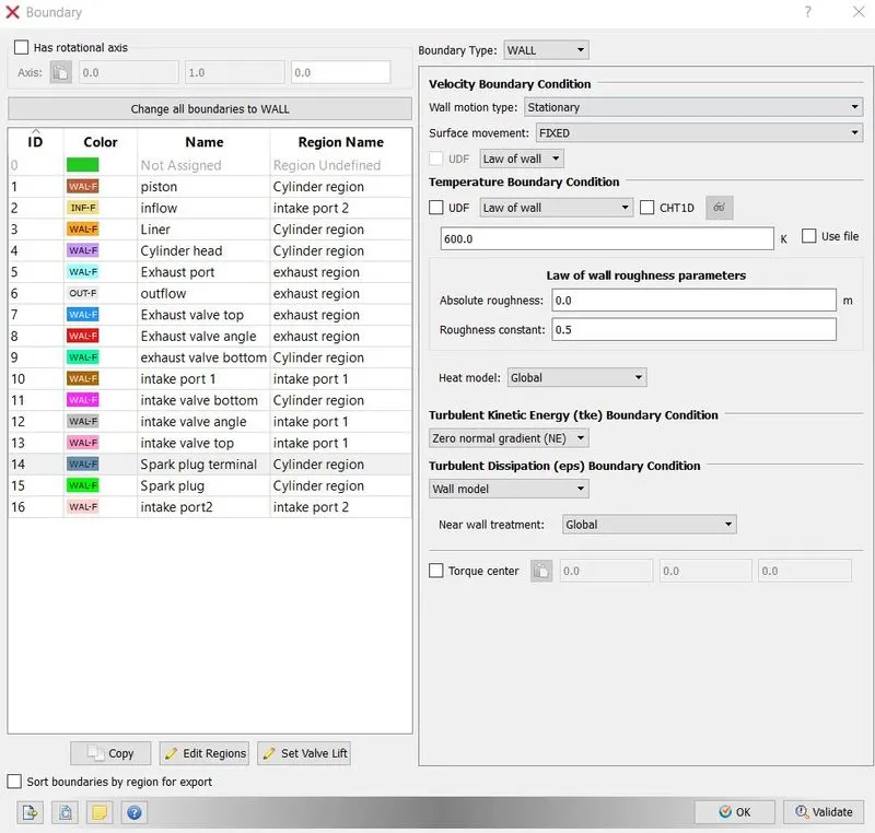
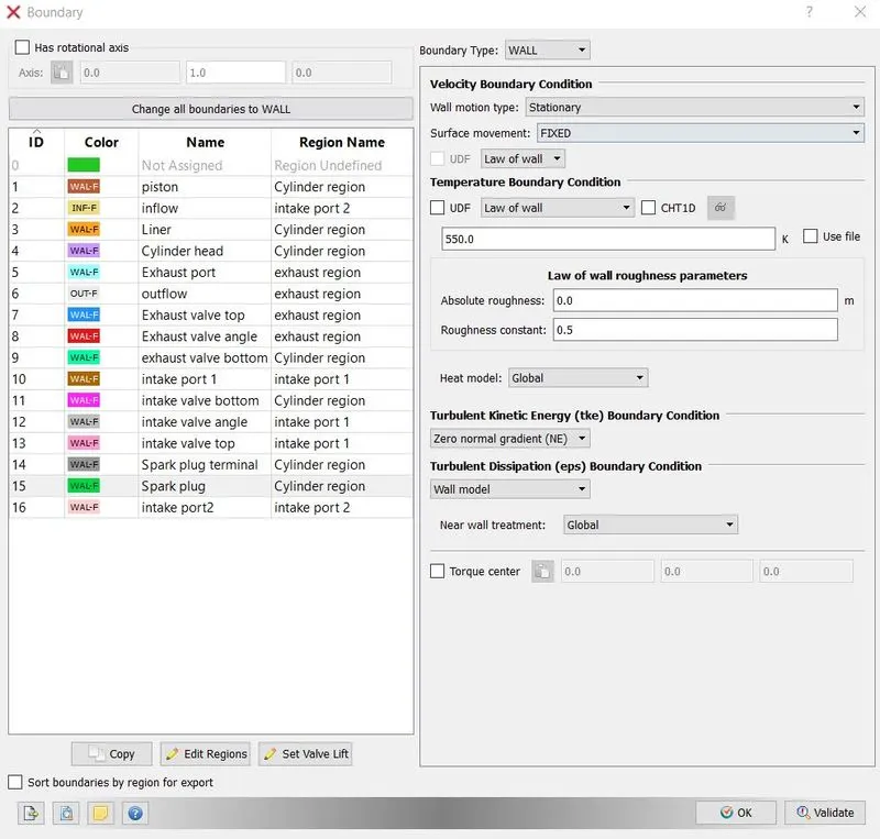
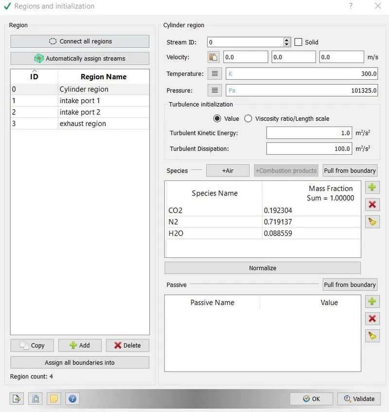
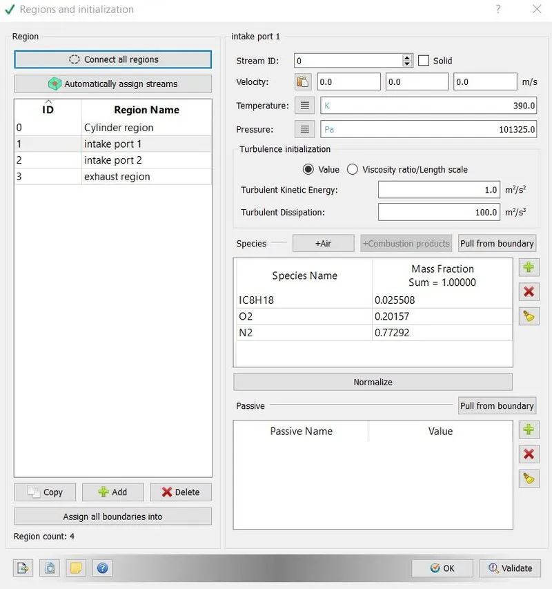
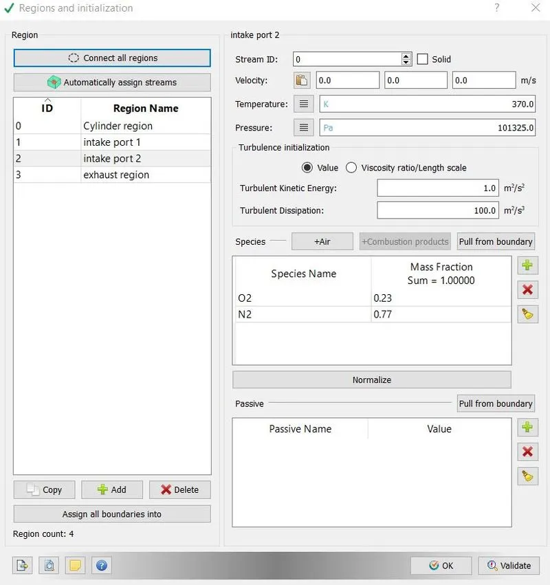
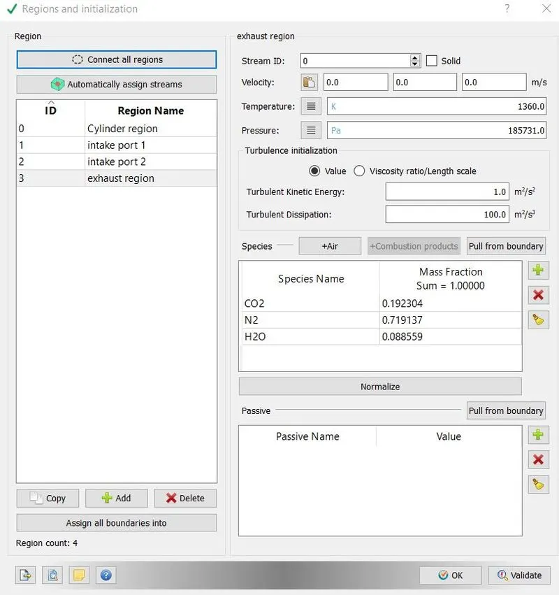
12. Four major regions were defined named cylinder region, intake port1, intake port2 and exhaust region. Region allows us to defined region-specific properties like exhaust and inlet region can not have same properties.
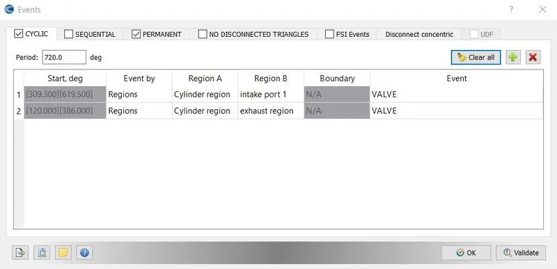
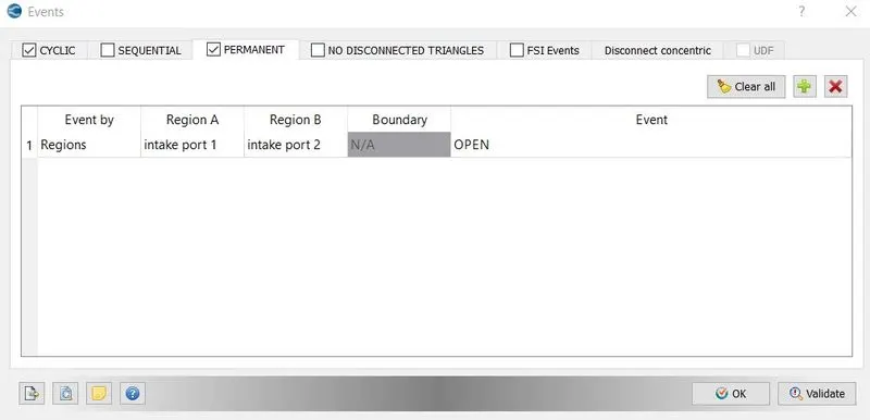
13. Event were enabled in initial conditions and even option and we specified three events, two were cyclic which would replicate valve movement and one event was permanent which specified no barrier between intake port 1 and intake port 2.
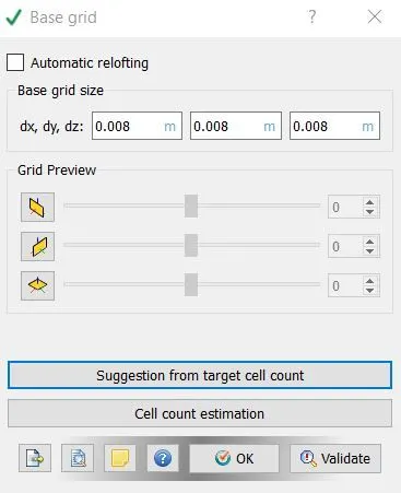
14. We chose k-epsilon turbulent model and base grid was chosen as 0.008m because we were performing no hydrodynamic simulation and these parameter does not have any effect on simulation.
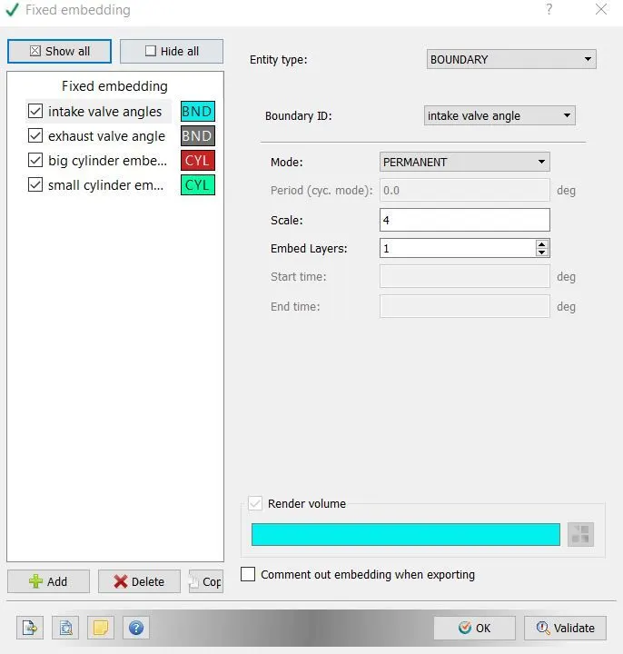
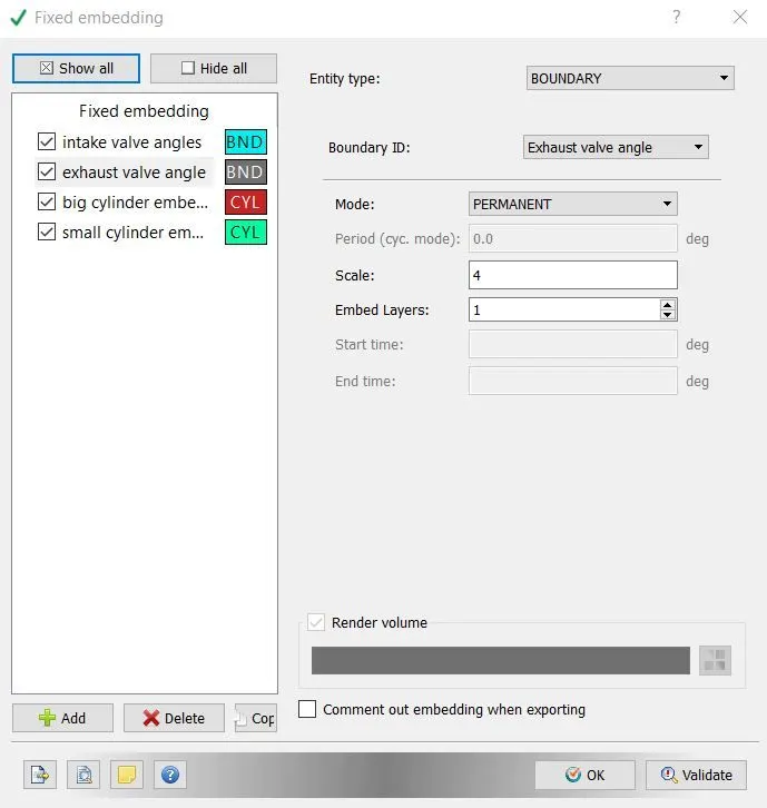
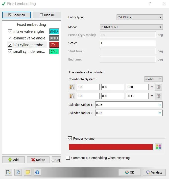
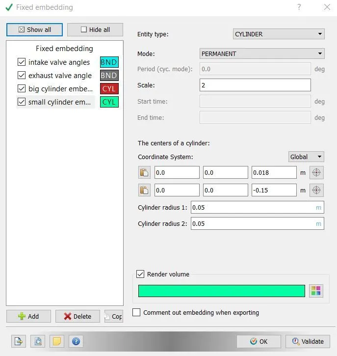
15. Fixed embedding option was enabled to get finer, the parameters was given as follows-
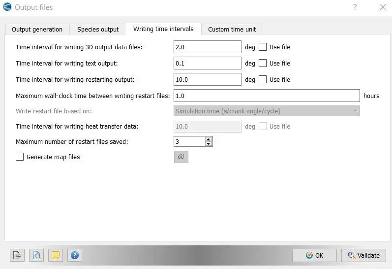
16. We went with default output parameters in output files menu.
6. Results -
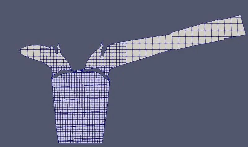
The main aim was of this study to run surface flagging, mitigate errors and run no hydrodynamic simulation to capture mesh movements. Converge provides special feature for IC engine simulation, we can enable piston, valve movements simply we don’t need to tell converge, how piston moves in cylinder, it automatically put motion in piston after we enable piston motion in boundary condition and it is similar for valve movement also. Surface preparation and boundary flagging has successfully done and after case setup we created an animation to see valve and piston movement, which can be seen by following link.
https://drive.google.com/file/d/1PlfJzglBcKTK_5Nznx3S5JuWa1XMVLFu/view?usp=sharing
Mesh -
at time step number 100
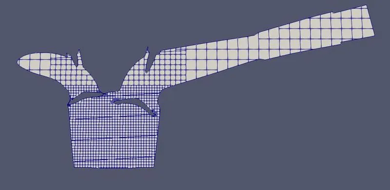
at time step number 150
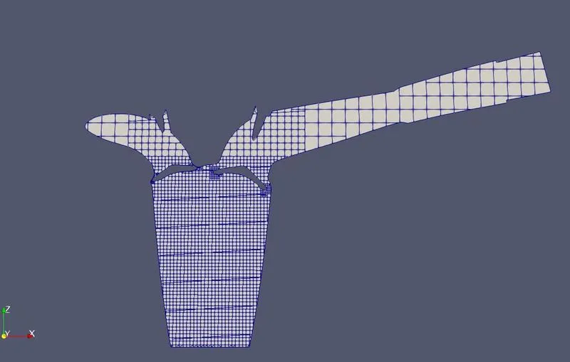
at time step number 300