Week-6 : Turbocharger Modelling
Turbocharger – A turbocharger is a machine which, compress the air entering an engine, increasing the amount of air that enters and thereby increasing the power output. The turbocharger is composed of two main parts - the compressor, which compresses the air in the intake and the turbine, which draws the exhaust gases and uses them to power the compressor. Compresses further compresses air and send it into cylinder.
Types of Turbocharge –
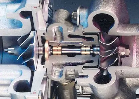
1. Single turbo - single turbo consists a turbine and compressor and related mechanism. The setup of a single turbo is much simpler. Differing the compressor wheel size and turbine will lead to completely different torque characteristics. Large turbos will bring on high top-end power, but smaller turbos will provide better low-end grunt as they spool faster.
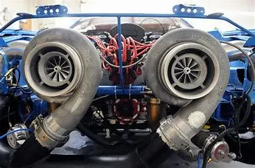
2. Twin turbo – As the name implies twin-turbos mean adding a second turbocharger to an engine. In the case of V6 or V8 engines, this can be done by assigning a single turbo to work with each cylinder bank. Alternatively, one smaller turbo could be used at low RPMs with a larger turbo for higher RPMs.
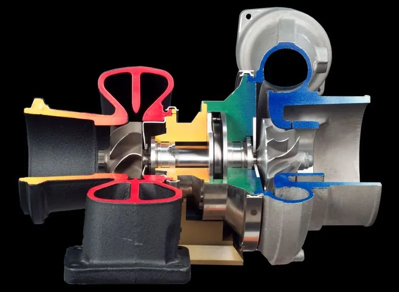
3. Twin scroll turbo - Twin-scroll turbo eliminates the irregularities of a regular turbo. Cylinders in an ICE fire at irregular intervals, releasing combustion gases in irregular pulses. This interference of exhaust gases doesn’t allow the ICE to harness its power in its entirety. ICEs with twin-scroll turbos, fire alternate cylinders at a time (1-4 and 2-3 in four pot engines), allowing exhaust gases to release in a synchronized alternating sequence.
4. Variable geometry turbo –The blades inside this turbocharger can mechanically change the effective diameter of the turbine. This helps in scenarios where the flow rate of the exhaust gases is low or high. In the case of low flow rate/low RPMs, the blades close up so that the size of the turbine decreases. When the turbine becomes smaller, it can be rotated even by a low flow rate and the purpose of spooling up the turbo is achieved. When the RPMs increase, the blades open up and the complete diameter of the turbine is exposed. This effectively means that the size of the turbocharger increases. The effects of the turbocharger will be experienced at a wider range of RPM levels. This helps counter the effect of turbo-lag to some extent.
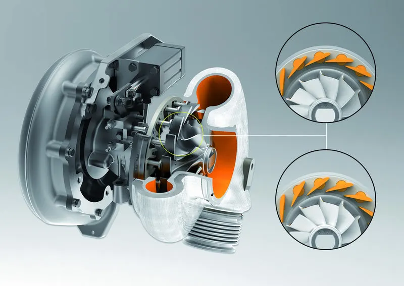
Variable geometry turbocharger is used where high air-fuel ratio and high torque is required at low speed. It improves EGR rates. On diesel engines, at low engine speeds, smoke emissions can be reduced significantly due to the ability of the turbocharger to adjust the air-fuel ratio. NOx emissions can also be reduced thanks to the increased backpressure in the exhaust manifold. Negative pressure difference across the engine increases the exhaust gas flow into the intake manifold.
5. E-turbo - An electric turbocharger is used to eliminate turbo lag and assist a normal turbocharger at lower engine speeds where a conventional turbo is not most efficient. This is achieved by adding an electric motor that spins up the turbo’s compressor from start and through the lower revs, until the power from the exhaust volume is high enough to work the turbocharger.
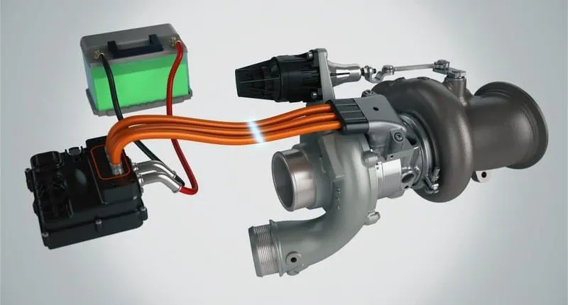
Models with turbocharger in GT power -
1. Single turbo -
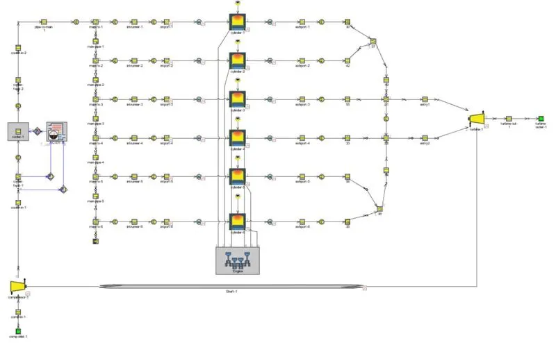
2. Twin turbo -
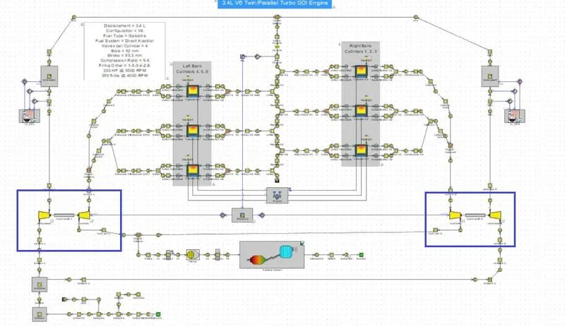
3. twin scroll turbo -
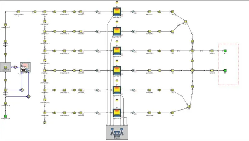
4. Turbo with wastegate -
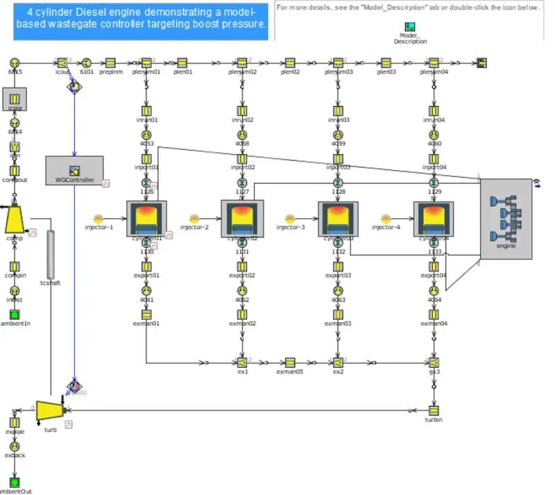
Model6 (Tutorial6) –
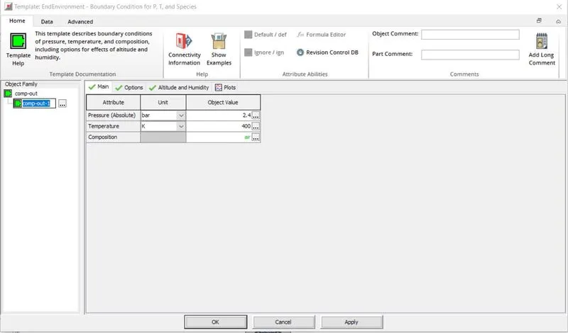
Compression outlet -
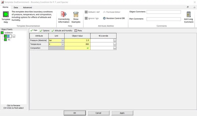
Turbine outlet -
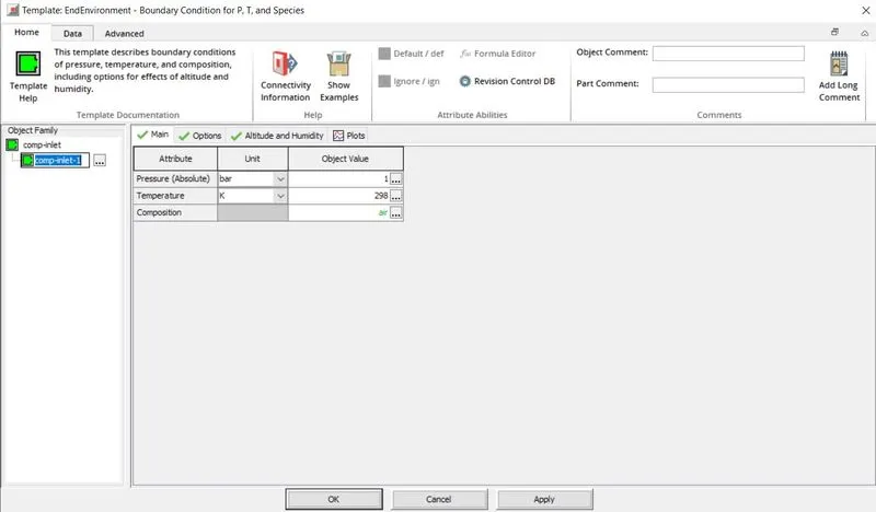
Model7 (Tutorial7) –
inlet and outlet (Ambient)-
Both are models are same except the method to show turbocharger, in model of tutorial 6, there is no block which can represent turbocharger, we just give the parameters which we can anticipate from the turbocharger. The red box in the image indicates the two outlets, which is represented as two entries of turbine inlet. It is a twin scroll turbo. Normally we take 1bar pressure and 300K temperature to represent the ambient, but here pressure is 2.4bar with 400K temperature at inlet, that why we can assume that there is mechanism which is compressing the air, albeit that is not represented.
In model 7, we can see there are some blocks which is representing turbine, compressor and connecting shaft.so, it obvious there is a turbocharger. Compression is taking air in at 1bar pressure and 298K temperature and turbine is leaving exhaust at same condition. These are the conditions of ambient.
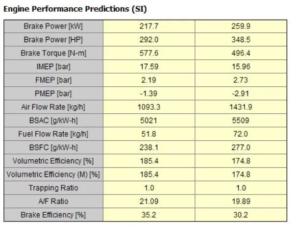
To better understand we generated some results from both the models, which can be seen in following images –
Results -
Model6
Model7 -
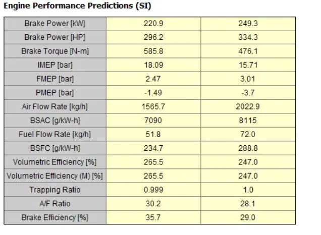
From the images it is clear that, model 7 has better volumetric efficiency prediction and air flow rate is higher that model 6 with same amount of fuel. the pressure difference across compressor is 2.6bar in model 7 and we gave 2.4bar in model 6at inlet, this could be the reason of the variation in the results. So, someone should prefer model 7 over model 6 for better prediction, because in model 7 compression and turbine speed varies according to the mass flow rate of air and exhaust and model 6 the pressure and temperature at inlet and outlet are constant, which contradicts the pressure build up across compression at starting of engine.
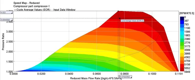
Compressor Map -
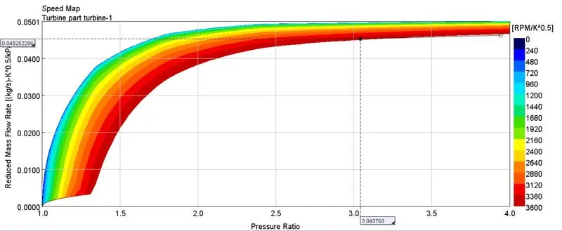
Model 7 is used to plot the operating points on compressor and turbine map. The dot on the map represents the operating point.
Turbine Map -
Diesel VGT EGR –
This model is facilitated with EGR, VGT, intercooler, injection limiting, boost control and exhaust after treatment device modelling. It is a predictive model means the parameters are dependent, change in one will affect another.
Model -
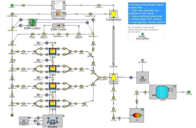
The engine is a 4-cylinder, four-stroke, direct injection, 2L diesel engine. The engine runs in "speed" mode, where the engine speed is entered by the user and the engine torque is calculated. Combustion is modelled by the DIPulse method, a predictive combustion model using the detailed injection profiles.
Intercooler reduces the temperature and increases the density of the air, which is coming from compressor.
Exhaust gas recirculation system is transporting the exhaust gases from exhaust to intake manifold. It is working in a close loop system means it limits the recirculation based on the EGT target fraction.
The exhaust system is modelled with Diesel Oxidation Catalyst, diesel particulate filter and muffler, for aftertreatment.
Compressor and turbine assembly is there for turbocharging. Compressor is modelled with fixed geometry and turbine is modelled with variable geometry, for this five different maps are given as rack position.