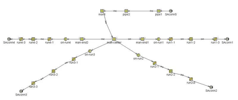
Week-11 : Discretization of 3D intake manifold using GEM-3D
Model –
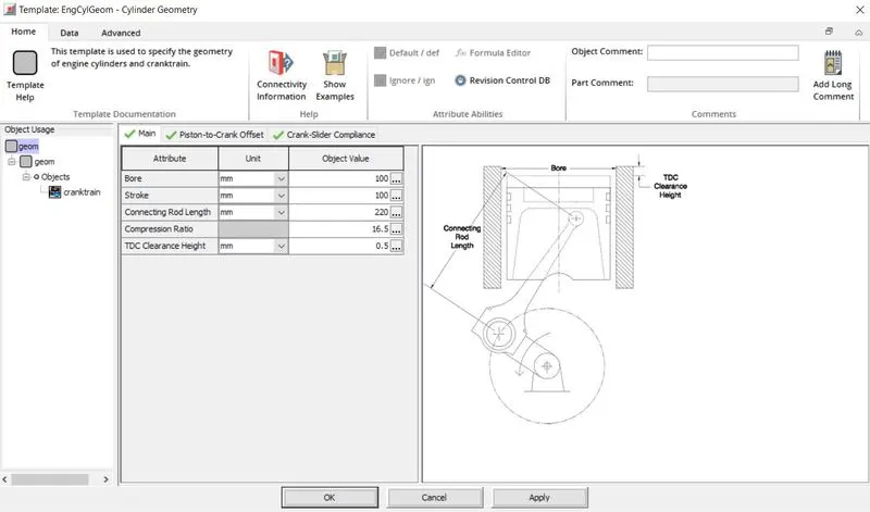
Cylinder geometry -
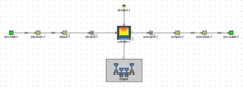
This is a simple model representing a CI engine with direct injection as mode of fuel inlet. Engine has single cylinder. Intake system taking air at ambient condition and at the same condition exhaust system is expelling air, means there is no turbocharger.
Case setup –
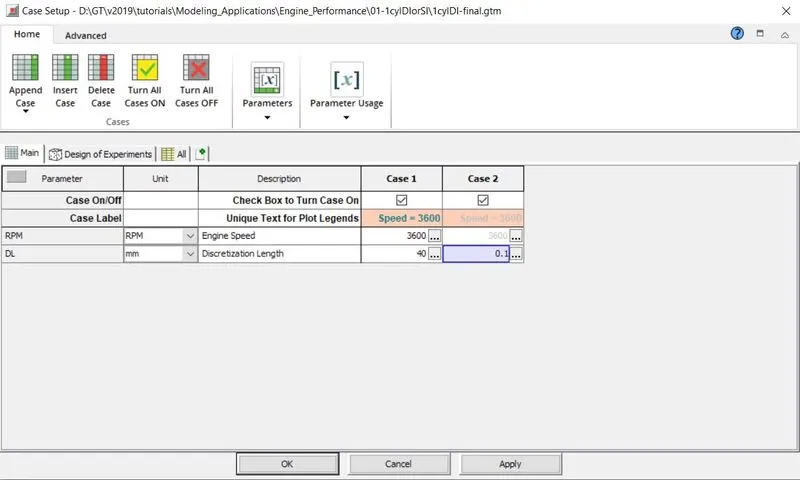
In case one discretization length is 40mm and we changed it to 0.1mm in case2 for intake runner.
Result -
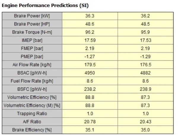
Engine performance indicators -
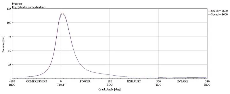
In cylinder pressure -
case 1 in indicated by red color and case 2 is indicated by blue color.
Case vs simulation time -
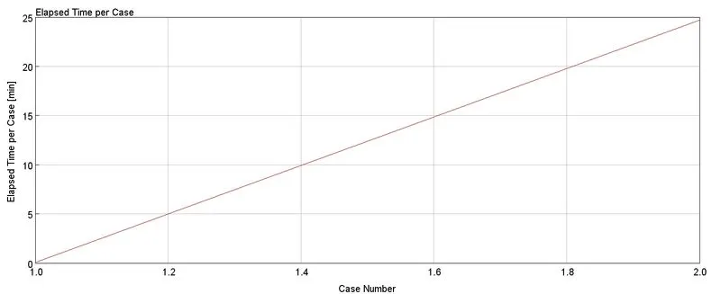
We wanted to detect the changes which comes with discretization length, for that we setup two cases and simulated. It is obvious that greater discretization length is going to less time than smaller, to strengthen this we can see plot – case vs real time. Second thing, we need to see the accuracy of the result, because discretization length will affect it. It is clear from the engine specification that change in discretization length corrected some parameters, but in not great manner. BSCF increase from 238.2 g/KW-h to 238.9 g/KW-h torque has decreased from 96.2 Nm to 95.9Nm. maximum in cylinder pressure is floating around 120bar. so, We need to select between accuracy and simulation time on the priority bases.
Building intake manifold from STL model –
Procedure –
Step 1-
CAD model -
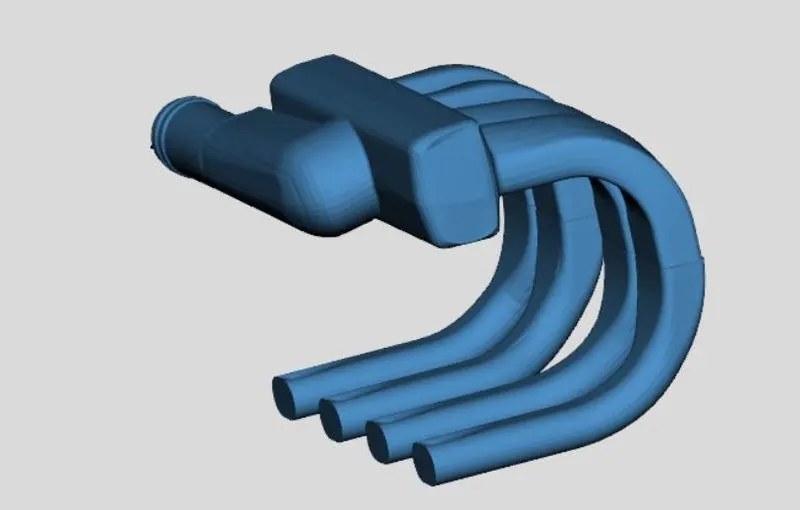
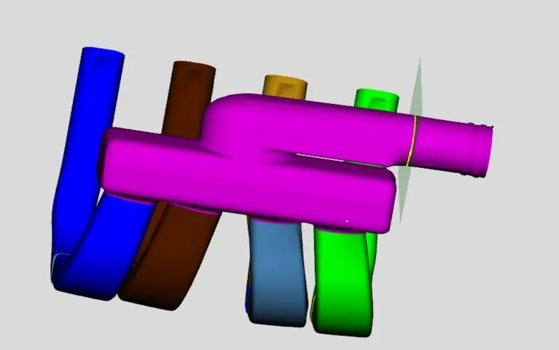
Import the CAD model bu using open option in file menu and it or can be access directly in spaceclaim using GEM 3D option.After importing geometry, it we can see that the inlet and the ends of the 4 intake runners are closed. We need to remove these caps so the ends are open and available for flow. To do this, we will use the Separate by Curves operation. This will separate the geometry into parts based on changes in the surface of the object. This process will also separate the intake runners into two different sections near the area change at the top of the runners. Ensure the part is selected and choose Separate by Curves from the Shape Operations group in the Convert tab. After it, remove all caps.
Step 2 –
Using cutting plane – Now, we can continue separating the shape into sections that can be represented by pipes and flowsplits. We will start by separating off the 4 runners from the manifold since the runners can be represented by pipes. To do this we will make use of the cutting plane operations available in the Cutting Planes group in the Convert tab. To enable the cutting plane, select 3 Points Cutting Plane from this group. A cutting plane can then be created by clicking on 3 points on the model to define a plane. Since we want to cut off the runners, let's pick 3 points on the underside of the manifold block and click on clip option.
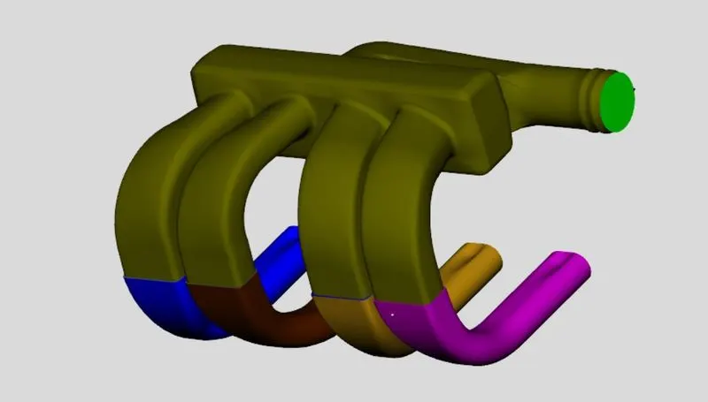
after removing caps -
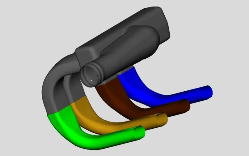
Section separation -
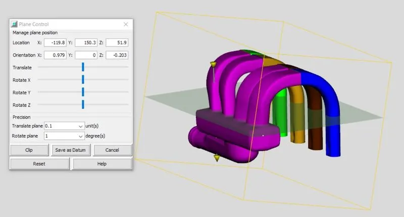
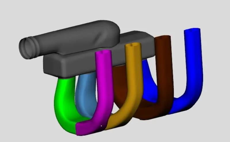
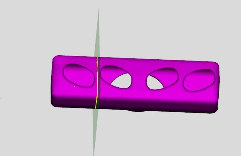
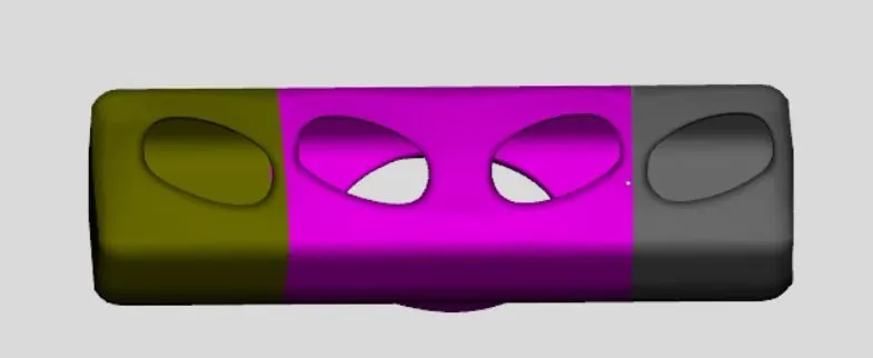
Step 3-
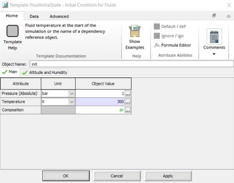
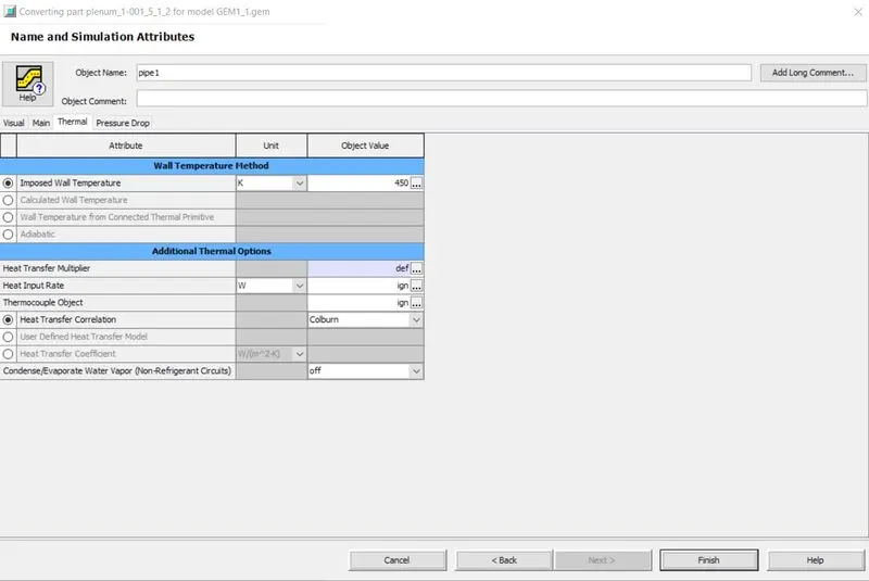
Converting section into flow connection -Once we have sections that can be represented by pipes or flowsplits we need to convert them into flow components. This is done with the convert mesh operation. To begin the conversion, right-click on the any section and select Convert Shape to Component.
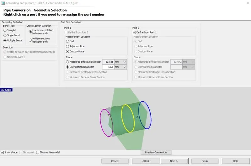
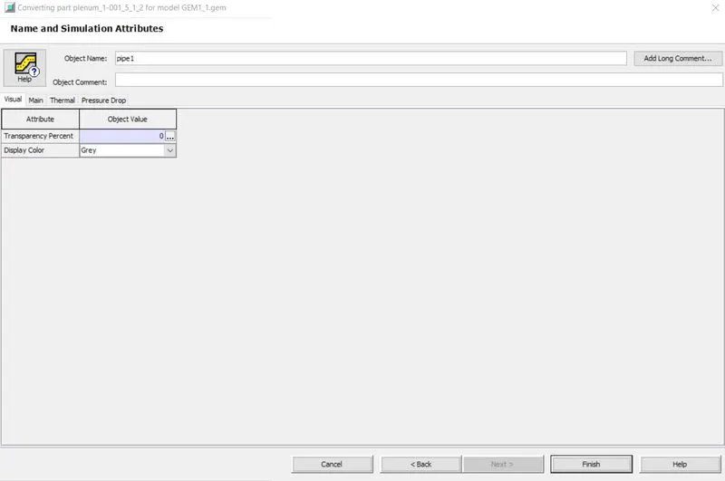
initial conditions (in main)
Step 4-
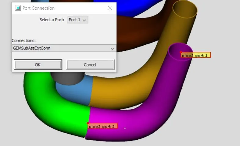
Adding a custom connection - In the conversion process for the runners, information regarding the curved entry from the manifold (fillets) was lost. This curved entry would represent a better flow transition than a default orifice connection, so we need to manually add an orifice connection to represent this. To add a custom orifice to a flow component right-click on the first section of runner 1and choose Add Connection. This will open the port connection window, shown in the image below, that allows the selection of which port to add the connection to and what type of connection to use.
Step 5 –
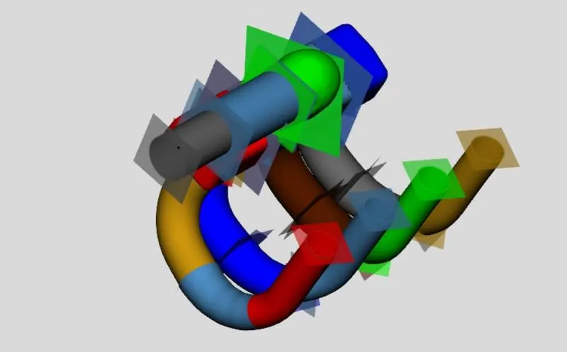
Adding flow connections - we created several pipes which do not align perfectly. To remedy this, we can use the flow connection operation to join the runner sections at the top of the manifold. To do this, select Flow Connection > Flow Connection from the Connections group under the tab Flow. This will show available surfaces for adding flow connections, as shown below.
Step 6-
Discretizing the model - Now that the model consists entirely of flow components, we can discretize the model. First, save the model again using the save toolbar button or choosing Home/Save. To discretize a model, select Export GT Model from either the Home tab or the toolbar. This will open the discretization window that contains the available discretization options.
Discretized model -