Week 8 - Simulating Cyclone separator with Discrete Phase Modelling
1. Title –Simulating Cyclone separator with Discrete Phase Modelling.
2. Objective –
- To Import the CAD model of cyclone separator in Spaceclaim and generate flow volume.
- To mesh the model with suitable sizes in Ansys mechanical.
- To set solver with suitable model, boundary conditions and solve.
- To calculate separation efficiency and make particle time and pressure drop contour.
3. Introduction –
Cyclone separator is a device which is used to remove particulate matter from flue gases. The flow the tangential inlet, which gives rise to an axially descending spiral of a gas and a centrifugal force field that causes the incoming particles to concentrate along wall and settle down.
Cyclone separator are used by many industries to remove pollutants from air, water and gas. This devise can be manufactured in any shape and size. It has used in cyclone grease separator- removes tiny grease particle from air, Horizontal dust collectors – to remove dust and other particles from manufacturing plants, Hydrocyclonic separator – removes solid particles from fast moving water etc.
4. Theory -
Pressure drop and collection efficiency are the two major criteria used to evaluate cyclone performance. In the cyclone design, getting great efficiency is main aim and this can be achieved by altering dimensions and some factors. There are many empirical models to validate the theory of cyclone separator efficiency.
Pressure drop model of Dirgo - Dirgo developed an optimization program to investigate design changes that would improve performance. The model was developed through statistical analysis of pressure drop data for 98 cyclone designs, a substantially larger data set for evaluation of pressure drop models than has been used previously. Pressure drop was expressed in terms of gas inlet velocity heads. The pressure drop is given by following formula-

`v_i` = gas inlet velocity
`rho_G` = gas density
`rho_L` = liquid density
g = gravitational acceleration
`Delta H` = Height related to pressure drop
The change in dimension at the outlet should be in concern with the inlet dimensions. The inlet height and the inlet width should be change in proportion so as to improve the cyclone performance.
Lapple model is amongst the earliest of model proposed and is still considered bench mark for design of cyclone separators in many industries. This is comparatively a simple model based on force balance with considering the flow resistance. It assumes that the particles are evenly distributed across the inlet while entering the cyclone. It was based on terminal velocity of particles in cyclone.the following formula was derived by Lapple to find separation efficiency -
`eta = 1/(1+(d_(pc))/d_(pa))^2`
`d_(pc)` = 50% cut size
`d_(pa` = particle diameter
Iozia and Leith model - It considers simple force balance on particle in cyclone. It assumes that centrifugal force and drag force act on particle and balance each other. The collection efficiency η developed a logistic model based on Barth is given by-
`eta = 1/(1+(d_(pc))/d_(pa))^beta`
Leith and Licht took account the temperature on top of other factors. It assumes that there is no slip in the tangential direction between the particles and fluid that is, both particles and fluid have same tangential velocity. Also, it considers relation VR n = constant for relation between tangential velocity V and radius R. the efficiency calculated by following formula-

Efficiency formula for this study -
`eta` = number of particle trapped/(Number of particle tracked - Incomplete particles)
5. Procedure –
In this we wanted to find separation efficiency at particle diameter from 1u to 5u with flow velocity and particle velocity 3m/s. in second case we wanted separation efficiency with particle diameter 5u and particle velocity from 1m/s to 5m/s. the following procedure was followed -
Geometry –
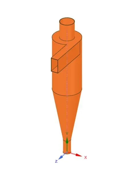
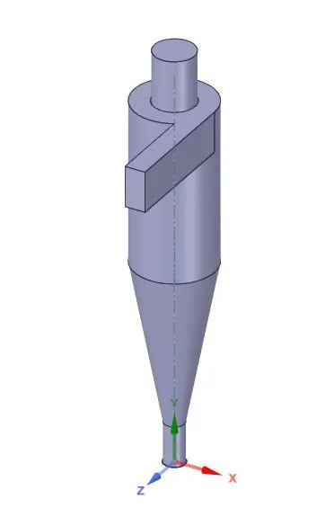
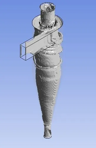
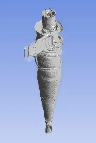
Cyclone separator has very simple geometry and it has no rotating part also. 3D model of cyclone has created in Solidworks and imported in Spaceclaim to clean geometry and to generate volume for fluid flow, using volume option in prepare menu.
Cyclone separator solid -
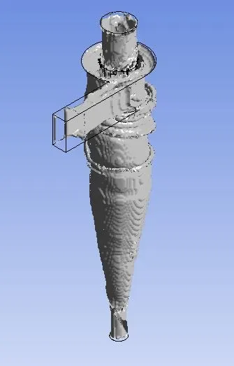
Cyclone separator flow volume -
Meshing –
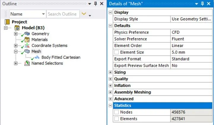
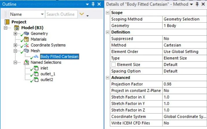
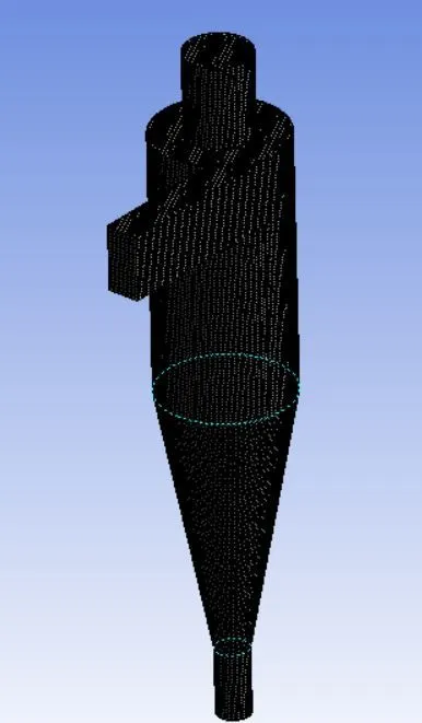
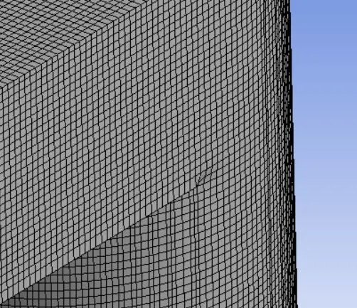
After volume generation model has brought into Ansys mechanical for meshing. Proper element size and meshing is very important because it affects results greatly. Body fitted cartesian mesh has generated because it is fits well in geometry and Cartesian approach makes handling complex and moving geometries much easier and accurate by cutting the cells rather than stretching and compressing the cells to fit. Global size of is 5mm used in order to achieve sufficient number of elements because number of particles in discrete phase mixing directly depends on it. Named selections are created which will be later used to apply boundary conditions.
Meshing parameters -
Generated mesh -
Solver setup –
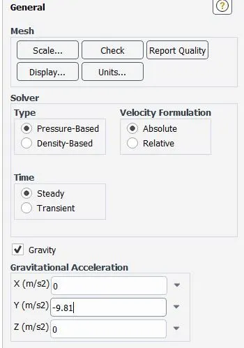
After meshing solver setting step comes. The flow is assumed is assumed to be steady, turbulent, incompressible and isothermal. We used pressure base solver because flow has velocity less than 3 Mach. We proceeded with steady state solving option because we are not taking time into account. We enabled gravity option and gave value -9.81m/s^2 because gravity is working in negative y axis in our model.
General Setting -
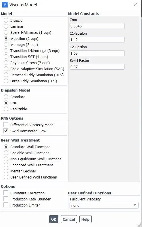
We chose k-epsilon RNG model (due to the anisotropic nature of the turbulence) to represent the turbulent flow and enabled the RNG option swirl dominated flow to catch swirl properly. Discrete particle model is used to forecast particle trajectories and collection efficiency. The particle equations of motion are solved to track the particles trajectories in the flow field and also the relevant forces acting on each particle are taking into account. Surface injection type was created at inlet with suitable value of velocity and density. Different velocity will be used with different density in this simulation, to study about the effect of both factors on separation efficiency.
Solver model -
DPM -
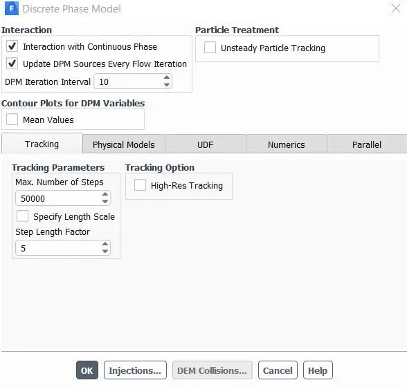
Injection Properties -
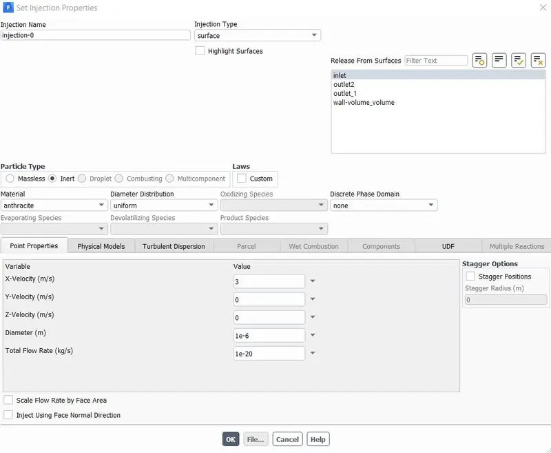
Default material was already Air, so we could proceed further without altering it. Inlet velocity and discrete phase boundary condition are the only boundary conditions used in this simulation. Discrete phase boundary condition type was set to escape at top outlet, trap at outlet bottom and reflect at inlet and wall.
Inlet boundary conditions -
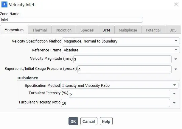
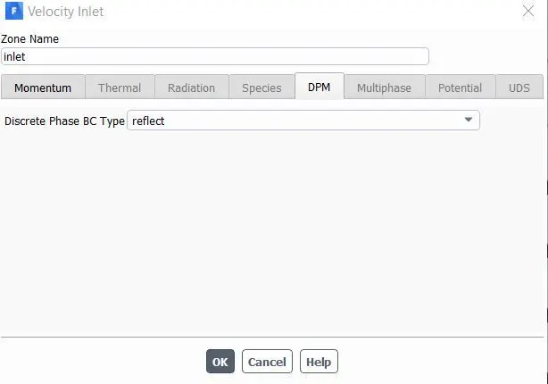
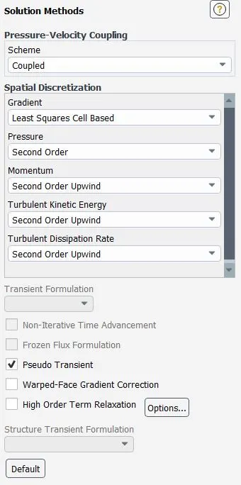
In solution method second order equation was used of turbulent kinetic energy and turbulent dissipation to increase accuracy.Standard initialization method used because we have one inlet and it proceed with solving equation for initial guess.
Solution method -
Results –
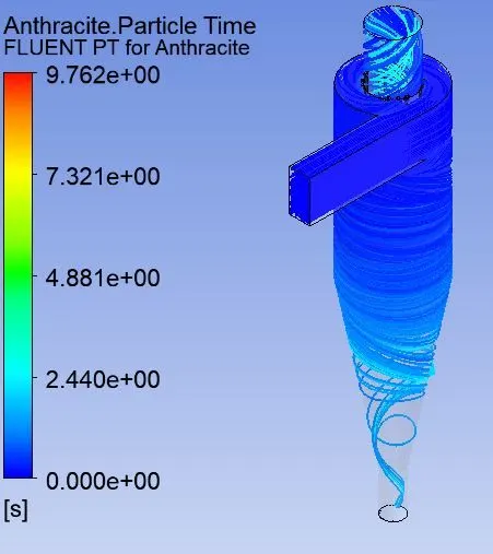
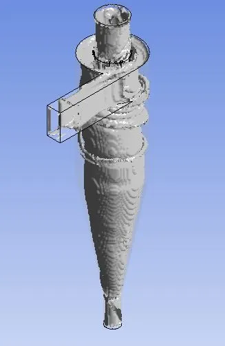
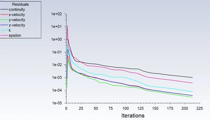
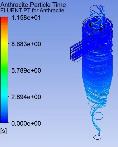
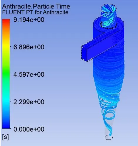
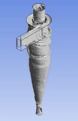
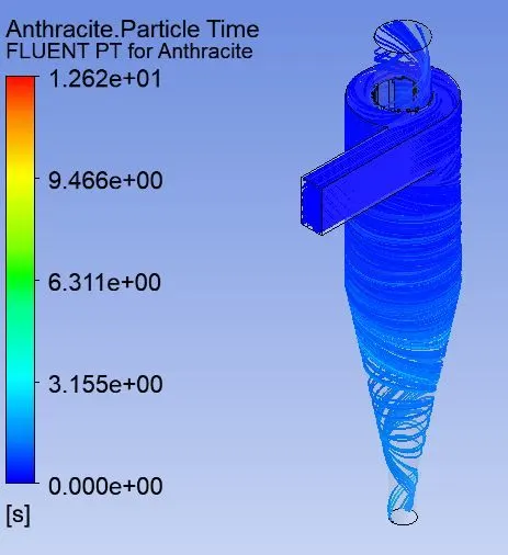
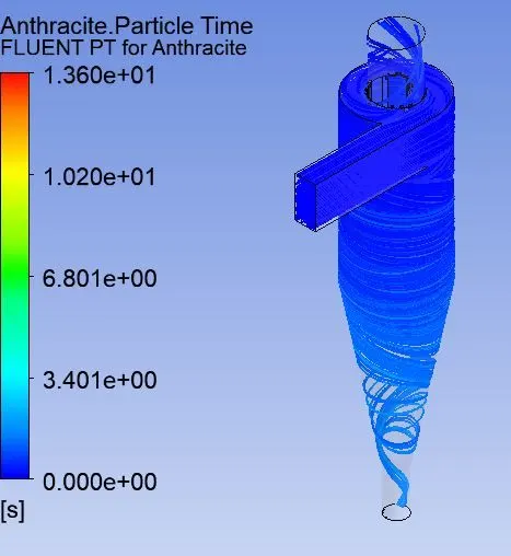
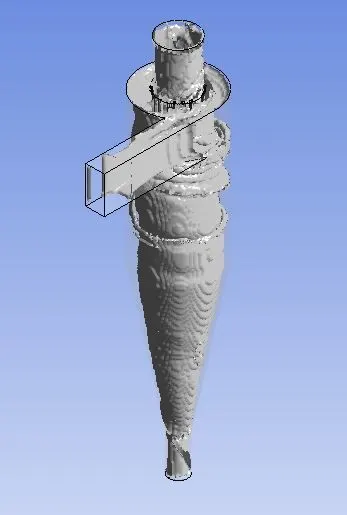
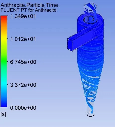
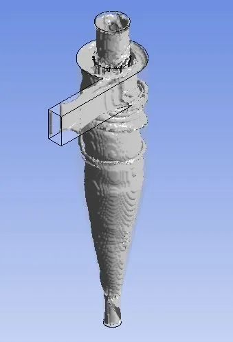
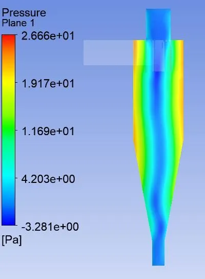
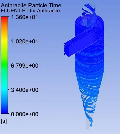
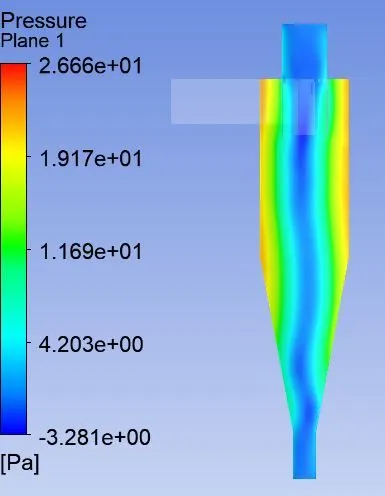
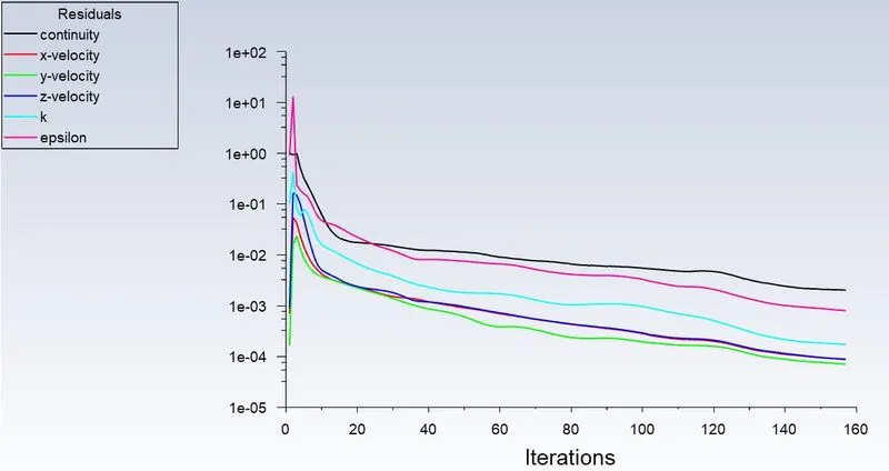
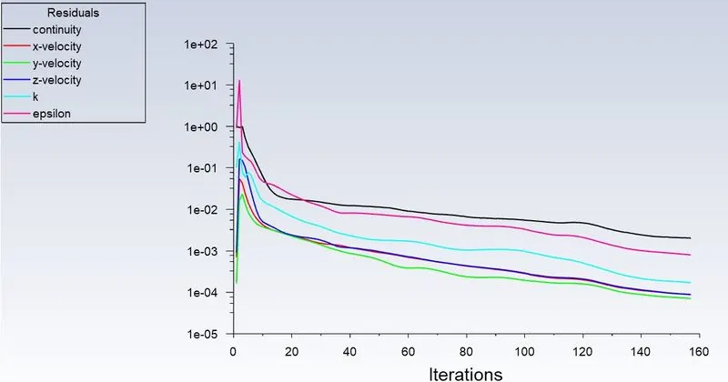
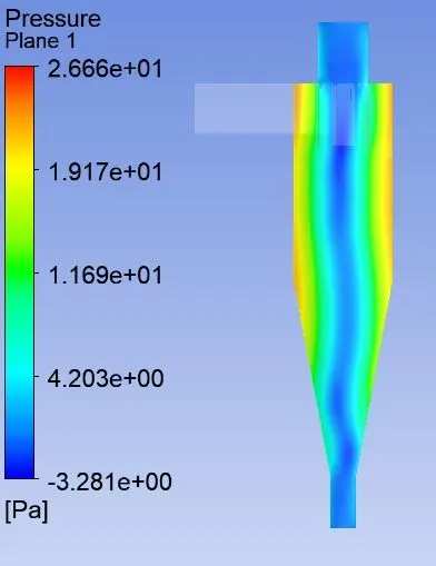
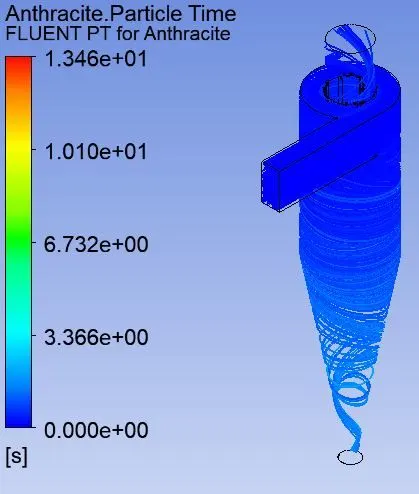
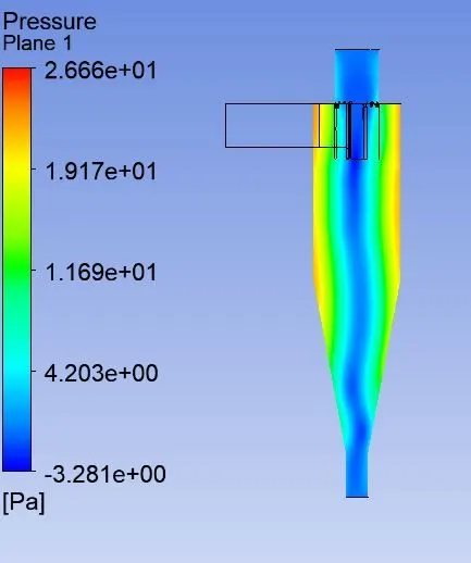
The study was conducted to see effect of particle diameter and velocity on separation efficiency. Contour of pressure drop has also created to gain more detail about flow pattern. The following contour, vortex and velocity streamline was crested in CFD fluid. Pressure drop across the cyclone plays a significant role in its overall performance so pressure drop contour has created from those It can be stated that the total pressure drop trough the cyclone increases with decreasing the vortex finder diameter and vice versa.
Case 1
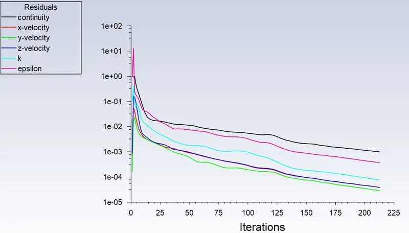
In this case simulation has performed with 3m/s flow velocity and particle velocity with particle diameter varying from 1um to 5um.
a. Particle diameter - 1um
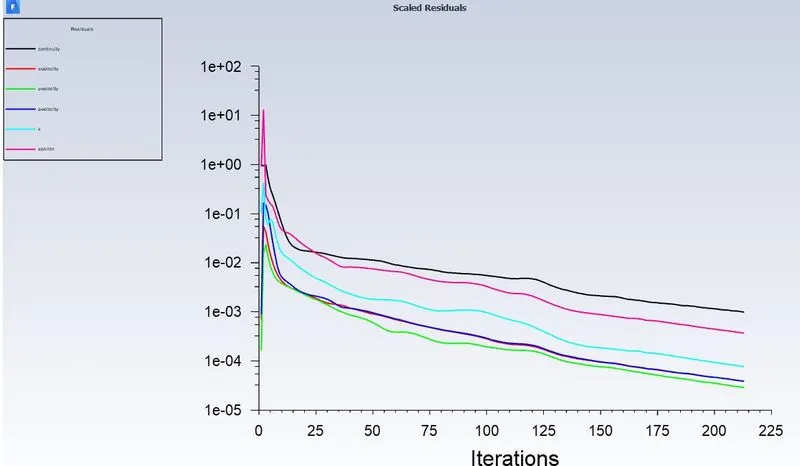
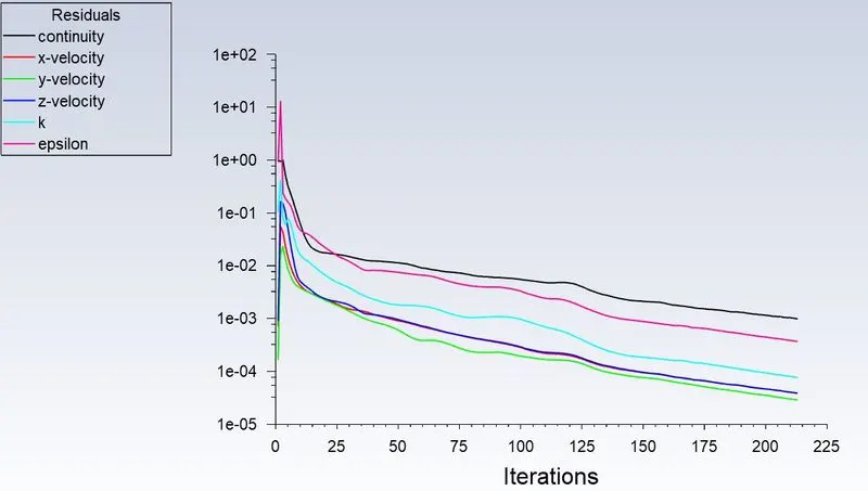
Residuals -
Particle time and velocity streamline -
Generated Vortex -
b. Particle diameter - 2um
Residuals -
Particle time and velocity streamline -
Generated Vortex -
c. Particle diameter - 3um
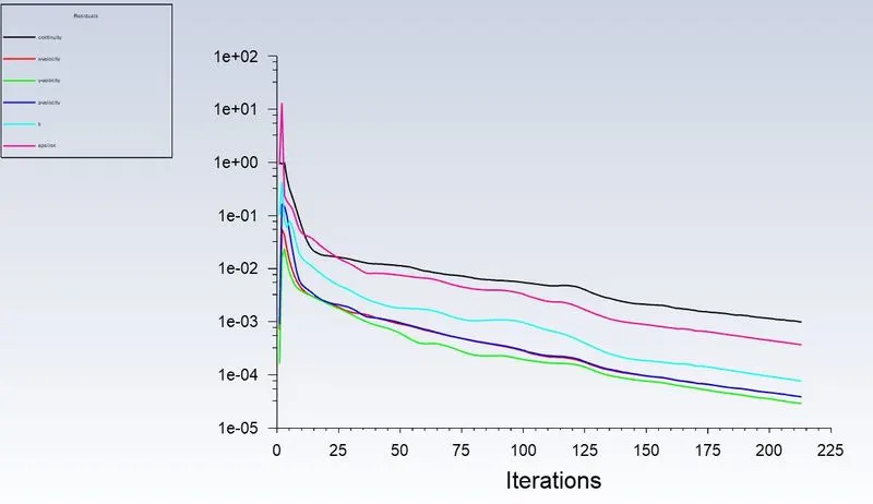
Residuals -
Particle time and velocity streamline -
Generated Vortex -
d. Particle diameter - 4um
Residuals -
Particle time and velocity streamline -
Generated Vortex -
e. Particle diameter - 5um
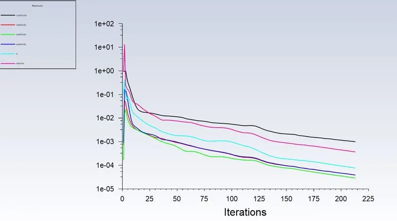
Residuals -
Particle time and velocity streamline -
Generated Vortex -
Case 2
In this case simulation has performed particle diameter was kept constant and particle velocity and flow velocity has varied from 1m/s to 5m/s.
a. Particle Velocity and Flow Velocity - 1m/s
Residuals -
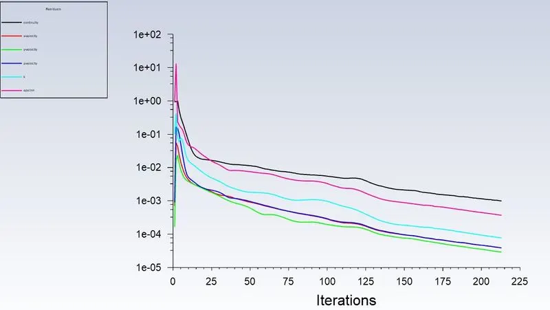
Particle time and velocity streamline -
Generated Vortex -
Pressure Contour -
b. Particle Velocity and Flow Velocity - 2m/s
Residuals -
Particle time and velocity streamline -
Generated Vortex -
Pressure Contour -
c. Particle Velocity and Flow Velocity - 3m/s
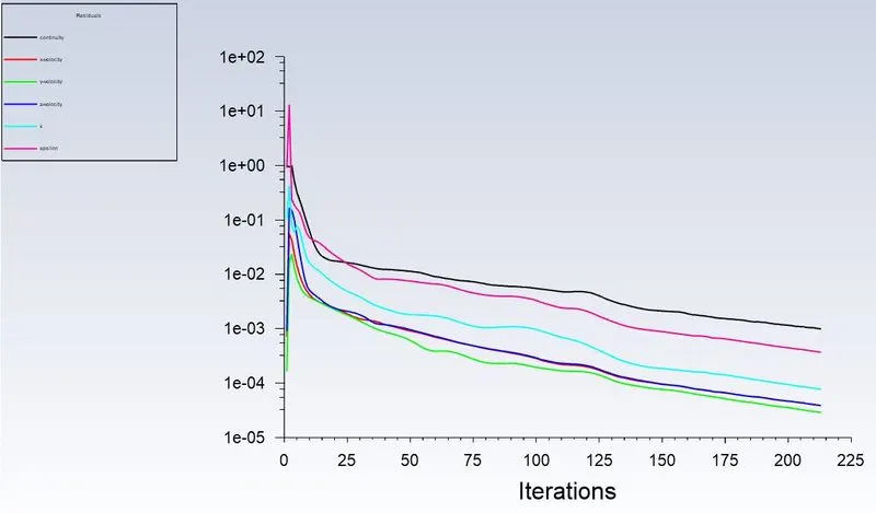
Residuals -
Particle time and velocity streamline -
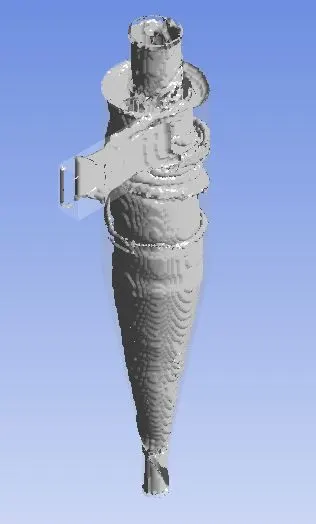
Generated Vortex -
Pressure Contour -
d. Particle Velocity and Flow Velocity - 4m/s
Residuals -
Particle time and velocity streamline -

Generated Vortex -
Pressure Contour -
e. Particle Velocity and Flow Velocity - 5m/s
Residuals -
Particle time and velocity streamline -
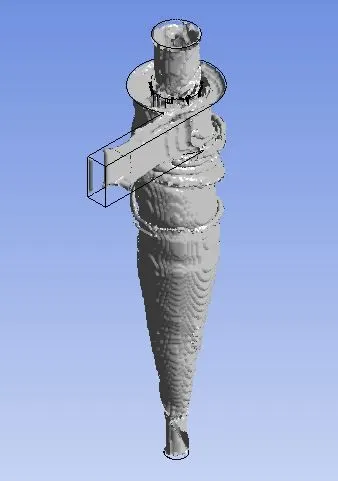
Generated Vortex -
Pressure Contour -
Results at a glance -
Case1 -
|
Particle diameter(um) |
Particle and Flow velocity(m/s) |
Number of iterations to converged |
Tracked particles |
Trapped particles |
Incomplete particles |
Separation efficiency (%) |
|
1 |
3 |
213 |
378 |
112 |
120 |
43.41 |
|
2 |
3 |
213 |
378 |
143 |
109 |
53.15 |
|
3 |
3 |
213 |
378 |
172 |
108 |
63.70 |
|
4 |
3 |
213 |
378 |
200 |
101 |
72.20 |
|
5 |
3 |
213 |
378 |
251 |
55 |
77.77 |
Case2 -
|
Particle diameter(um) |
Particle and Flow velocity(m/s) |
Number of iterations to converged |
Tracked particles |
Trapped particles |
Incomplete particles |
Separation efficiency |
|
5 |
1 |
213 |
378 |
264 |
41 |
78.33 |
|
5 |
2 |
213 |
378 |
250 |
55 |
77.39 |
|
5 |
3 |
213 |
378 |
251 |
55 |
77.72 |
|
5 |
4 |
213 |
378 |
242 |
64 |
77.07 |
|
5 |
5 |
213 |
378 |
254 |
52 |
77.91 |
6. Conclusion –
A numerical technique based on CFD approach is used in this work to study the flow of air and particles through cyclone. Reynolds Stress Model methodology is used to predict the turbulence behaviour of the flow and Discrete Phase Model is used to predict the particle trajectories through cyclone separator. All the dimensional parameters of cyclone are kept constant except particle diameter, fluid velocity and particle velocity. We can infer from the results that separation efficiency increases with increase in particle diameter and it remains stable if inlet velocity is increased. Optimization of cyclone separator model is possible using numerical techniques of CFD approach.