Week 8
Study -
Practice all the Morphing techniques that were shown in the video for the given component.
Write a report on Morphing and its use cases in various industries.
1. Title – Morphing In ANSA
2. Objective –
- To understand about morphing technique and its uses
- To reshape given CAD model and create some new features using morphing tools.
3. Introduction –
ANSA morphing toolset offers an explicit approach to capture a wide range of CAE model iterations between two technical surfaces releases. This is very effective means to CAE lead design and development. Without CAE modelling, technical assessment and feedback it is difficult if not impossible. ANSA morphing aids rapid CAE model iterations to a technical surface like bonnet, door, sunroof etc. It offers the ability to compile additional models from the transition between two surface releases. Kinetics supports the articulation of such a technical surface release.
In ANSA most of the morphing modification can be applied both on FE and Geometric models. The function of morphing deck can be used to reshape shell and solid FE models avoiding returning back to CAD modification and meshing. Application of morphing can be found in durability, Crash, CFD etc. In this study we going to see some basic morphing techniques.
4. Morphing technique in ANSA –
ANSA has a particular deck dedicated to morphing techniques. Morphing can be applied in ways in ANSA first one is box morphing and other one is direct morphing.
A. Box morphing – this morphing is performed by boxes, which is made by user at region where morphing is required. Boxes have control points which can be moved in order to get required shape of selected region.
To perform box morphing, first select the option new from morphing deck and then chose geometry option from pop up menu.
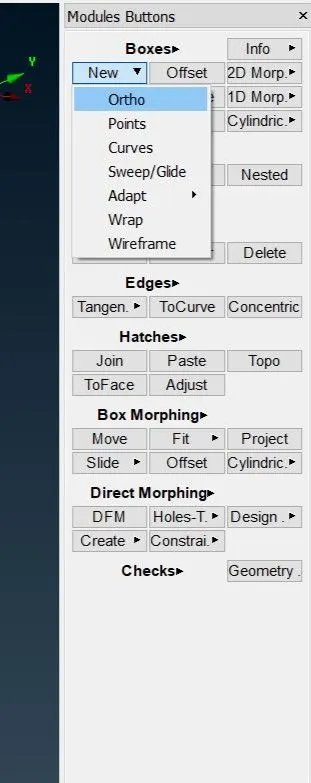
Fig. Morphing Deck
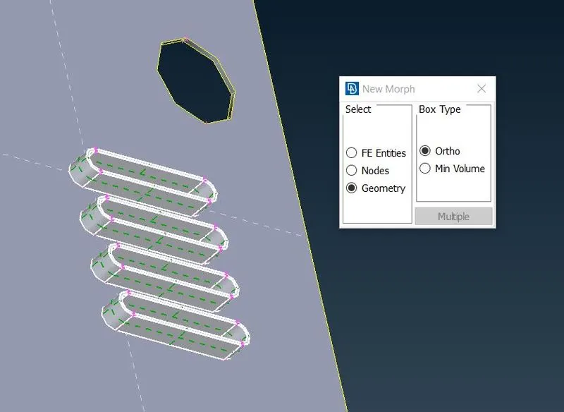
Fig. Box Morphing
Now select region to create box. Box will be in green colour.
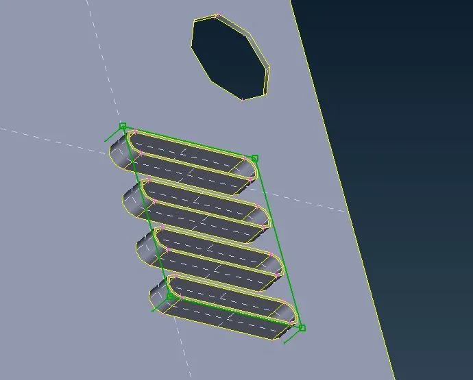
Fig. Box morphing
Further, select move option and then select control points and drag these in required direction to get required shape.
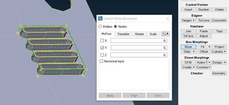
Fig. Direction Indication in Box Morphing
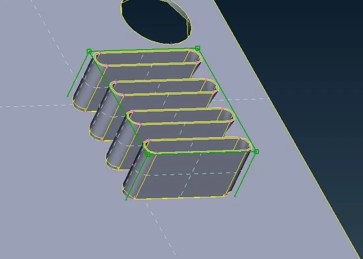
Fig. Reshaped Feature
Box morphing with split lines – this feature almost same as box morphing, but here box is splitted into many sections with split lines. This method is more prolific than other one because surrounding zone act as buffer zones of morphing action, which ensures the continuity of morphed areas. This is recommended where modification part affect surrounding parts too.
To perform this, follow the same procedure of box morphing. The little difference Is here in terms of control points, there will be more number of control points than previous one, due to split line which area specific and can be used to modify specific are like we a sharp bead as showing following images.
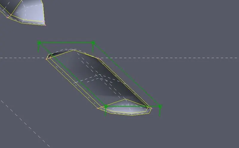
Fig. Box Creation
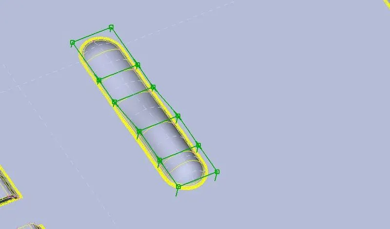
Fig. Box With Split lines
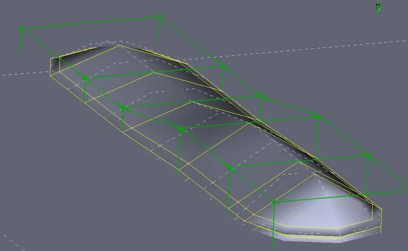
Fig. Reshaped Bead
For FE morphing select FE entities in pop menu. After morphing mesh can be reconstructed to get fine mesh flow.
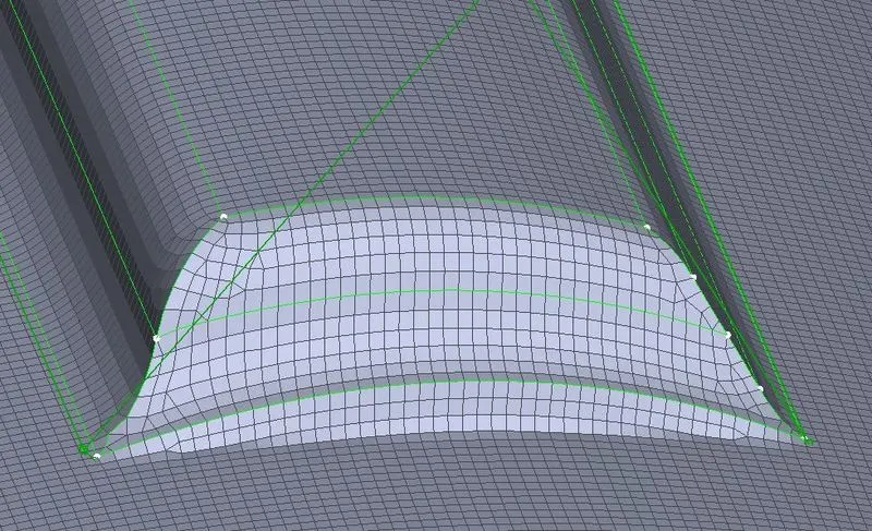
Fig. FE Box Morphing
B. Direct morphing – In this method morphing is performed without boxes. This can be performed either by specifying frozen, rigid node areas and morphing zones, or by fitting origin edges to target curves.
To perform this, select option DFM which abbreviation of direct morphing. Next, this function asks you to select area or line or nodes and then distance In any of axis. Mesh can be reconstructed to get best flow.
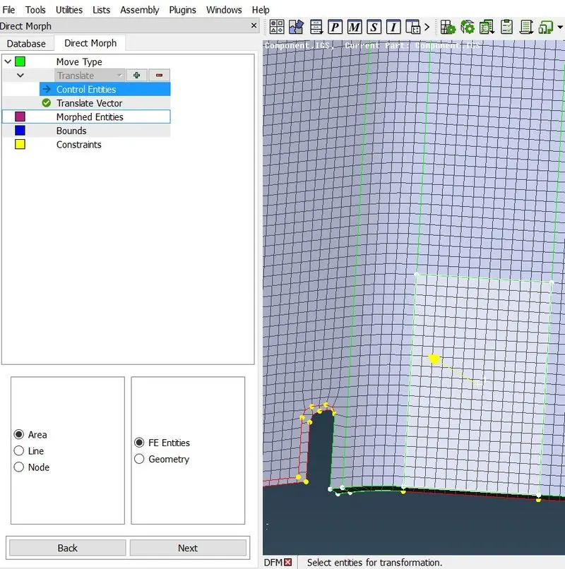
Fig. Direct Morph Manager
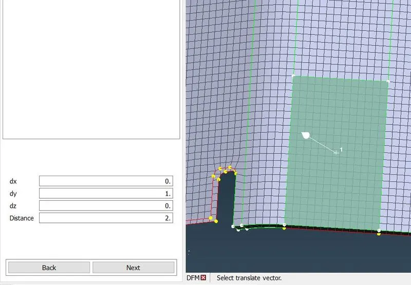
Fig. Assigning Direction Distance
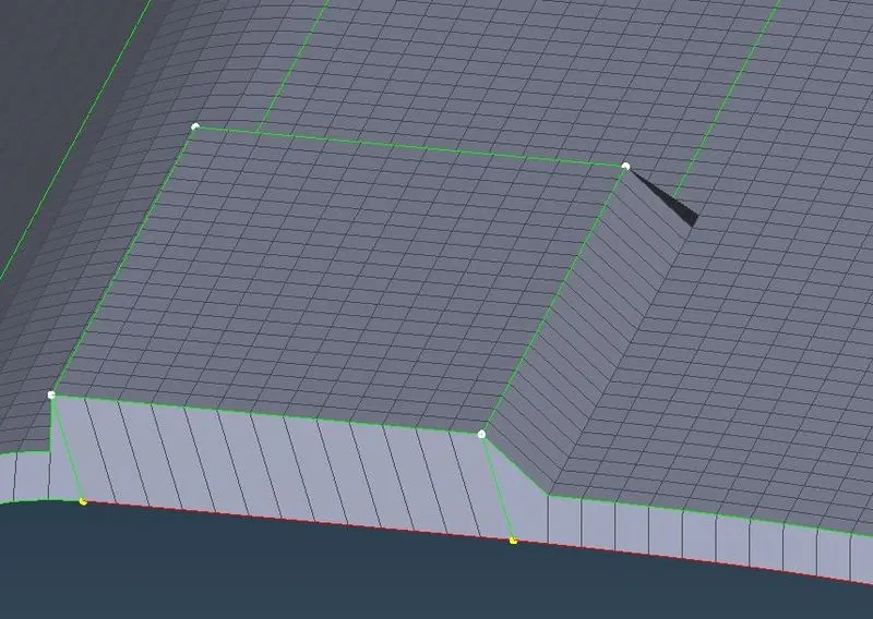
Fig. feature Created with Direct Morphing
Stamp, Bead, Flange opening etc can be created using feature creating tool.
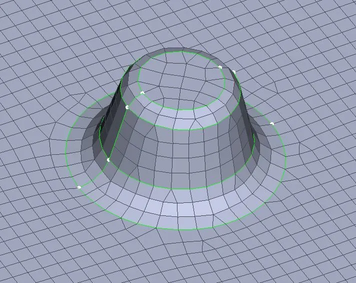
Fig. Stamp Created by Direct Morphing
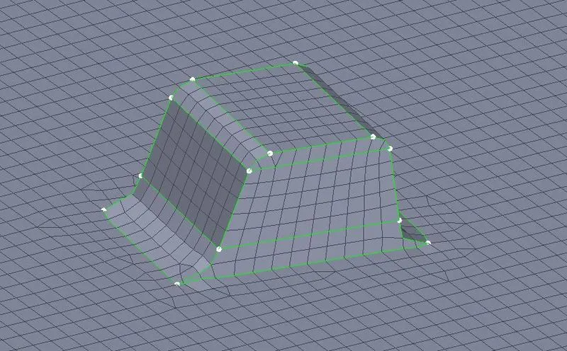
Fig. Bead Created by Direct Morphing
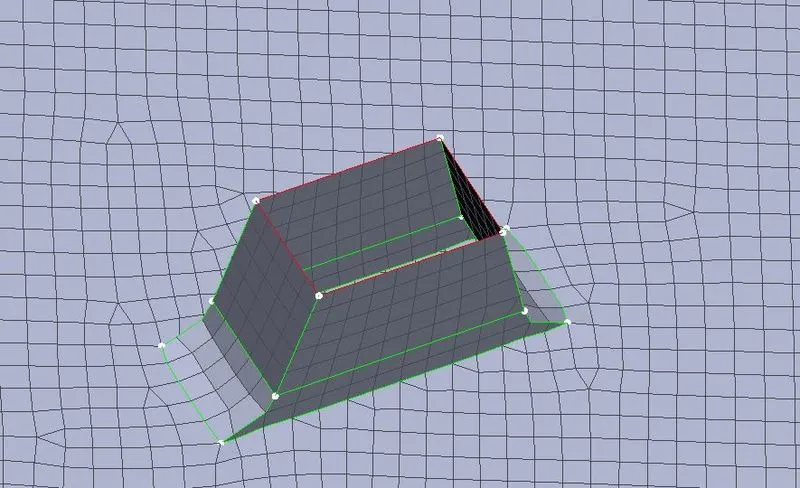
Fig. Flanged Opening Created by Direct Morphing
5. Scope of morphing –CAE morphing is an advance technique used to modify the shape of mechanical parts and assemblies without returning to CAD system, which is a time consuming process. In morphing automatic control block creation methods requires less expertise and effort. Easy morphing of CAE model parent design to a new concept or to match deign specification for two components derive from parent design. Automobile industry is using CAE morphing to create sedans from hatchback using from full vehicle morphing. For example- Suzuki swift desire is made from swift, a hatchback car, and Honda made amaze from brio.
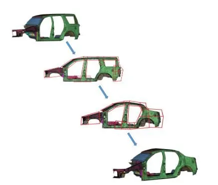
Fig. Full Vehicle morphing
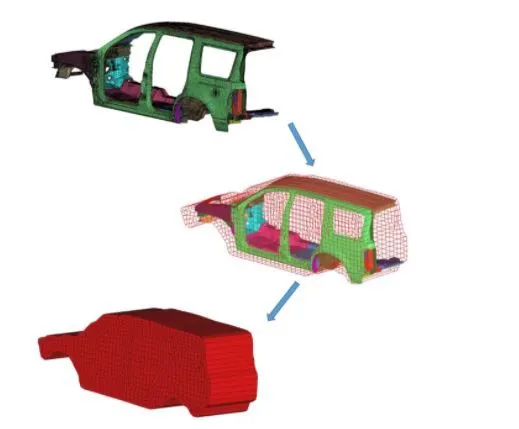
Fig. Auto Control Block Creation
6. Conclusion –
Mesh and geometry morphing has many advantages like – it is simple and fast, there is no need to reverse data from CAE to CAD, mesh with improved quality is possible after reshape, model parametrization is possible directly on mesh surfaces which further can be improved by optimization. Morphing technique is a promising step for future implementation of virtual reality and innovation in mechanical design.