FINAL TEST
PFI Engine queries
1. Compression ratio – it is the ratio between the total volume of the combustion chamber which is left when the piston is at its bottom dead centre and the volume left inside the combustion chamber when the piston moves to its top dead centre. compression ratio determines the thermal efficiency of used thermodynamic cycle of the combustion engine. In general, it is desired to have a high compression ratio, because it allows an engine to reach higher thermal efficiency. Petrol is very volatile, the compression ratio for Petrol engine is typically lower. Thus, it varies from 10:1 to 14:1. Whereas for diesel engine it varies from 18:1 to 23:1.
CR = Total volume/ clearance volume
Total volume can be written as , Displacement volume(`V_d`) + clearance volume(`V_c`)
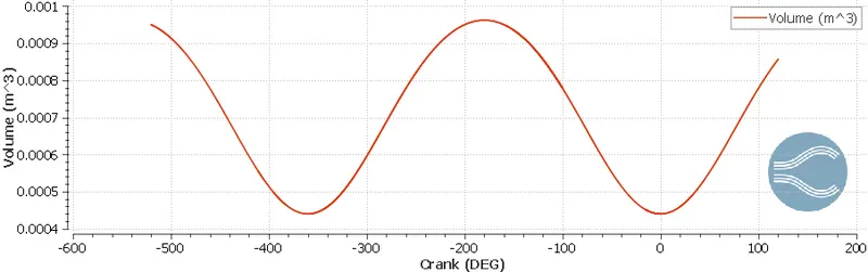
Volume measured from graph –
Maximum volume – `5.7240*10^-4 m^3`
Minimum volume – `5.7036*10^-5 m^3`
Compression ratio(C_r) = Maximum volume/ Minimum volume
CR= `(5.7240*10^-4)/(5.7036*10^-5)`
CR = 10.036
2. We need compression ratio 10.3 currently we have 10.036. we can change compression ratio by either changing displacement volume or clearance volume, while keeping geometric parameter constant.
Let’s assume displacement volume constant -
CR = `(V_d + V_c)/V_c`
`10.3 = (V_d + 5.7036*10^-5)/ (5.7036*10^-5)`
`V_d = 5.304*10^-4`
To get CR 10.3 we need to use above written displacement volume
Now, let’s assume clearance volume constant
`CR = (V_d + V_c)/V_c`
Maximum volume = `V_d + V_c`
`5.724*10^-4 = V_d + 5.7036*10^-5`
`V_d = 5.153*10^-4`
From the formula
`10.3 = (5.153*10^-4+V_c)/V_c`
`V_c = 5.541*10^-5`
To get CR 10.3 we need to use above written clearance volume
3. Volumetric efficiency – it is the ration of actual volume of intake air(`V_a`) to theoretical volume of cylinder(`V_t`).
`eta_v = V_a/V_t`
actual volume of intake air can be calculated by following formula –
`V_a` = air mass(`m_a`)/air density(`rho_a`)
Rho_a = air pressure `(P_a` )/Temperature(`T_a`)*Gas constant(`R_a`)
Rewriting volumetric efficiency formula –
`eta_v = (m_a)/(rho_a*V_t)`
We have –
`R_a = 287J/(Kg*K)`
`V_t = 5.724*10^-4 m^3`
`P_a = 101325Pa`
`T_a = 313K`
intake air mass(`m_a`) = `5.34*10^-4 Kg`
`rho_a = 101325/(287*(313)) = 1.128(Kg)/m^3`
`eta_v = (5.34*10^-4)/(1.128*5.724e-4) = 82.70%`
4. Air mass flow rate = intake air*engine speed
=`5.34*10^-4*50 = 0.0267(Kg)/s`
5. Cell count varying due to adaptive mesh refinement feature. Adaptive mesh refinement option is very important because you can not deploy same sized mesh on whole model. Mesh can be rescaled on the basis of condition. like in velocity criteria, if we set sub grid criteria 1m/s then above it, cell will be become finer by a factor of 2^n, here n is embedded level, if it is 3 and mesh will get finer by 8 times.
6. Engine valve are mechanical components used in internal combustion engines to allow or restrict the flow of fluid or gas to and from the combustion chambers or cylinders during engine operation. The movement of these valve is regulated with cam shaft and spring and this mechanism do not allow gap between valves and cylinder head.
In our PFI model there were no such mechanism, can close the gap between valves and cylinder, we are talking about the spring mechanism. That why there is gap, which appears during simulation. In simulation event were crated, which was making disconnecting triangles between cylinder and valves to fill the gap.
If there is big gap between cylinder and valves, then there is change of fuel bypass, means fuel can go into exhaust port during intake. This will lead into higher content of hydrocarbons in emissions. With respective to simulation, the same problem will be there and we would fail to get around the real phenomenon.
7. Engine speed = 3000RPM = 50 RPS
Revolution in degrees = 360*50 = 18000degree/second
Combustion time = duration of combustion (in crank angle)/ total revolution in one cycle = `240.199/18000 = 0.0133s`
so, combustion lasts for 0.0133 second.
Diesel Engine queries
1. When the geometry is symmetric about the any axis, we can retrieve results for a full 3D geometry by simply solving a portion of it. The portion we solved is called as sector and simulation called as sector simulation. Most important advantage is, it saves the computational time, result can be generated without compromising any parameter. Sector simulation leads to accurate results.
2. Sector simulation is useful when the geometry is symmetric and if we want to analyse close loop cycle. Sector simulation will not work in case of engine where valves are part of the simulation and they are moving, sector simulation will also fail in case of turbomachines, where they directly interacting with environment.
3. Crank angle refers to the position of an engine's crankshaft in relation to the piston as it travels inside of the cylinder wall. We know in four stoke engine crank shaft rotates twice in single power cycle. So, from angle 0 degree to 720 degree or -360 degree to 360 degree, four cycles can be divided. In diesel engine simulation we simulated emission characteristics only, means we were focusing only compression stroke and exhaust stroke only, angle at which compression start was Start Crank Angle and crank angle at which piston gets BDC after power stoke was End rank angle. We gave -147degree starting crank angle and 135degree end crank angle.
4. As we discussed in second point that sector simulation will fail, when there is open cycle analysis. In PFI engine simulation valves are there, which makes it open. So PFI case cannot be converted into sector case.