FINAL INDEPENDENT PROJECT
1.Title – Modelling and Rendering of Audi Q3 car.
2.Objective –
- Design and modelling of components of car, using sketch tools and 3D modelling features of Solidworks.
- Assembly of car using Solidworks assembly tool.
- Rendering images of car in Photoview360 and Solidworks visualization with different environments and views.
3.Introduction –
Audi Q3 is an automobile by Garman manufacturer Audi. It is a 5-door coupe, subcompact SUV car, targets lifestyle market rather than off-road. The production of Audi Q3 was stared in 2011, since then has launched in many variants. In this project we going to SOLIDWORKS software to model car and render photo realistic images using SOLIDWORKS visualization.
Audi Q3 specifications –
Manufacturer – AUDI AG
Designer – Julian Hoenig
Body style – 5-door coupe
Layout – Front-engine, four-wheel drive
Engine displacement – 1395cc(Petrol) and 1968cc(diesel)
Transmission –7-speed S-Tronic
Max. Torque – 250Nm(Petrol) and 380Nm(diesel)
Mileage – 16.9Kmph(Petrol) and 17.12Kmph(diesel)
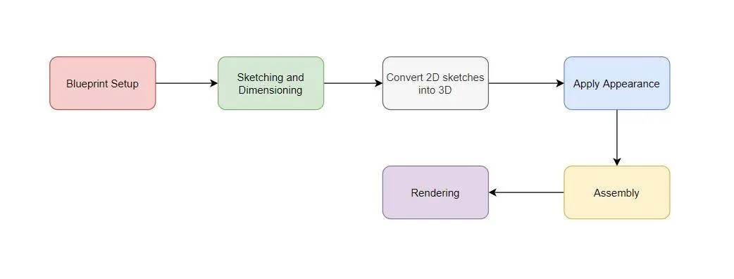
4. Design methodology –
5. Description –
3D modelling is the process of developing a representation of anything, it could be a real world thing like – car, bike, building etc. or an imaginary thing like – Sci-fi missiles, drones etc. 3D modelling has many types but for this we used surface modelling and solid modelling. In this project we used solid modelling features to model part of car and used surface modelling features to give shape to vehicle body and later we converted into solid body to give some extrudes and cuts. Journey starts with blueprint setup and ends with rendering.
The following parts are modelled –
Rim and tire –
Tire is ring shaped component surrounds rim, to transfer the load from axle to ground through wheel. Tires are pneumatically inflated provides a flexible cushion, that absorbs shocks. Tires is classified into two categories – tubed tires, tubeless tire. Further, they can be categorized according to type of ply -cross-ply, radial-ply and belted-biased ply.
Rim is the outer edge of a wheel, holds the tire. It has sealing function in tubeless tire. Rim can be categorized into one piece and multi-pieces, modern vehicle uses one-piece rims with a safety rim profile and heavy vehicles may have a removable multi-piece rim assembly.
Features Used – Boss extrude, Cut revolve, Cut extrude, Circular pattern, Dome, fillet and revolve.
Modelling Procedure –
- Start with a circle of 592mm diameter, in front plane. Extrude it 273mm.
- Now draw some rectangle with arc in right plane. Use this drawing to apply cut revolve feature, which results in some ring shapes on the rim.
- Draw slot in front plane, and use cut extrude to remove material from rim’s face.
- Use circular pattern feature, to distribute slot on face equally, with number of instances 5.
- Now draw a triangle with fillets, in between slots. Use cut extrude feature to remove material from face.
- Again, use circular pattern feature to make 5 instances of triangle.
- Now apply dome of 10mm on face and apply fillet of 5mm on the edged of slot and triangle.
- Draw circle in front plane and cut extrude it with a offset, that will indicate place of bolt.
- Apply dome on circular slot and pattern it with 5 instances.
- Make logo on centre of ring and extrude it 3mm and make a circular slot on the back side of rim face.
- Now draw a rectangle with 70mm height and width equal to rim. Use revolve feature to revolve rectangle which will results in a circular component mounted on rim. This is tire.
- Draw a rectangle with arc in right plane and use cut revolve to smoothen edge of tire.
- Make tread pattern on tire and cut extrude it. Distribute tread pattern on tire with circular pattern feature.
- Apply appearance and save the file.
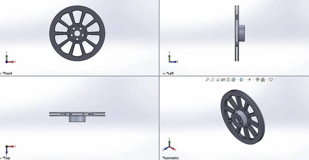
Rotor –
The brake rotor is a disc connected to tire’s hub, that is used in a disc brake assembly. As the caliper squeezes brake pad together, the rotor’s surface creates friction and which is further converted into heat. Rotor has four types according to construction – Drilled, slotted, Blank & smooth, drilled & slotted.
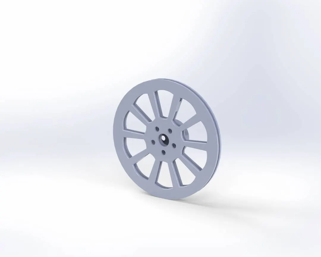
Features Used - Boss extrude, Cut extrude, Fillet, circular pattern and scale.
Modelling Procedure –
- Draw a circle of 22.23mm in front plane and extrude it 8mm.
- Now off-side outer edge of the face and cut extrude it 7mm to make a circular slot.
- Now draw circle in the front plane, pattern them and cut extrude it, through the face for bolt mounting.
- Make a disk on the opposite face and draw rectangular shapes on it. Extrude the rectangular shape, it will be used to attach other disk of rotor.
- Now make a similar disk on the opposite face.
- Make drawing of slot on the face of rotor and cut extrude it. Use circular pattern feature to make 10 slots on the face. After matching it in assembly, scale it with value of 5.2.
- Apply some fillets, appearance and save the model.
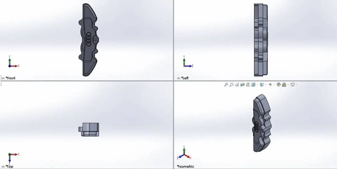
Brake Caliper –
Brake caliper is essential to stop car and arguably one of the most important component of brake assembly. Brake caliper squeezes the brake pads against the surface of rotor to slow or stop the vehicle. Most cars today use disk brakes due to its excellent performance.
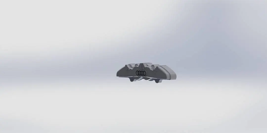
Features Used – Boss extrude, cut extrude, fillet and scale.
Modelling Procedure –
- Draw outer lining of clipper in front plane and extrude it 15mm.
- Now make another lining on the face of caplier and extrude it 15mm.
- Now make draw with lines and arcs to make shape, where it will be attached to rotor. Use cut extrude to remove material.
- Apply some fillets and repeat the step 3 on the opposite face of the caliper. Again, apply some fillet.
- Now draw Audi logo on front face and extrude it. Scale it with value of 1.6.
- Apply appearance and save it.
Vehicle body –
It is an automobile part which is integrated vehicle chassis. Vehicle body accommodates all other components like – wheel, door, steering mechanism, seats etc. the car body has different styles according to design like – hatchback, sedan, convertible, Coupe, SUV, van etc.
Features Used – Projected curve, Surface loft, Composite curve, Surface knit, Surface trim, Surface fill, Cut extrude, Boss extrude, Split, fillet, Split line, Reference plane, Chamfer, Mirror and Body-move-copy.
Modelling Procedure –
- Start with setting of blueprint. Create rear plane also. Blueprint should be with proper dimension and transparency.
- We are going to model hood first, it has 3 surfaces which will knitted together, later.
- Draw curves in mid plane and top plane, project them project them together to make a 3D curve. There will be eight curves limited, to their plane and four projected curves for each hood surface.
- Use surface loft command to make surface from four edges, two of them will be profile, and other two will be guiding curve.
- Repeat the step 3 and 4 to make other hood surfaces, with sticking to blueprint.
- Now knit surfaces together with allowing gap control.
- Now draw in front plane and covert the curve in top plane. Project them together and loft it. It is the extension of hood will be connected to grill.
- Now draw for head light and front bumper. Leave the space for head light. Surface below should be implanted. Use projected curve and surface loft.
- Start modelling for front fender. To make better fender in terms of slope make 4 circular surfaces. Surface will be slightly protruding, outward.
- Now use surface loft command and 3d curves to fill the remaining parts between front fender and hood, to get nice, smooth surfaces.
- Make a 3D vertical line on fender. Use this 3D line as trim tool and remove part which is intruding door. Knit the surface of fender.
- Now draw for door. Use edges of hood and front fender to draw curves with following curvature.
- Upper and lower surfaces of door will be slightly, protruding outward with different slope.
- Now use the same procedure, which is used for front fender. There will be four circular surfaces in rear fender as well.
- Now draw some straight lines using 3D curve feature to model middle part of door. It will accommodate circular surfaces of rear fender. Knit the surfaces of door and rear fender.
- Fill the gap between door and upper part of rear fender using surface loft feature.
- Extend the surfaces with same slope, which just below the mirror part, till the sloping of rear door, using projected curve and surface loft.
- Now construct for the surface, which is between front window and hood, this surface will be sloping downward towards window.
- Draw curves for front window and loft it. This surface will be upright.
- Now construct for roof. Roof is raising from front and it is flat in the middle and sloping downward at the end.
- Make projected curves for surfaces, which connects upper part of the mirror and lower part of roof. Knit the surface together. Split lines will be used to indicate side windows, later.
- Now draw curves for the rear part of, which is protruding and connects rear door.
- Construct curves for rear window. Rear window is more upright than front window.
- Now make some curves for the surfaces, rear roof line, which is truncated.
- Construct curves for tail light, split lines will be used to indicate LEDs later.
- Now construct for surface which connects lower part of trunk and rear reinforcement. It will accommodate brand logo.
- Now project some curves for the trunk surface, it will accommodate licence plate.
- Now comes rear bumper, use 3D curve with some construction line, to give same curvature as above surface. Knit the surfaces.
- Now construct some 3D lines, which is for surfaces below the door.
- Coming back to front reinforcement. Use surface loft and 3D sketch feature command to fill the area between headlight and bar absorber.
- Now project some curves to make boundary of grill. Use some 3D lines to make a surface which is slightly, outward, if we see it from side.
- Draw some straight lines and a curve using 3D sketch to model bumper, Lower curve should be in proper curvature. Later these will have some slots.
- Now, our car’s surface model is ready. Draw a horizontal line, an extrude it.
- Use surface trim command to trim extra surface, from which, is extruded earlier.
- Use surface fill command to fill bottom surface. Knit the surfaces and check make solid command, it will make solid body from surface body.
- Use cut extrude option to make space for grill.
- Now use some lines and rectangle, to draw shape for grill and extrude it.
- Again, use cut extrude feature to make some rectangular slot on bumper. Apply fillets on it.
- Make a rectangle, on the opposite side and cut extrude it. It will result in sloping surface.
- Use split line feature to construct bar absorber on the front reinforcement.
- Now draw a rectangle with fillets and extrude it. This will be license plate.
- Make reference plane at mirror area and draw a rectangle. Extrude it with some draft angle, outward.
- Take help of 3D sketch and draw mirror. Use surface extrude command to extrude it, piece by piece. Knit them, together.
- Now make a reference plane, at rear side, which is aligned with surface. Make rectangle and extrude it. Apply some fillets.
- Cut extrude at rear bumper for exhaust and construct rear light using split line feature.
- Use chamfer feature to make a sloping surface at lower edge of rear bumper.
- Again, use some split line to indicate front side windows.
- Use cut extrude feature, to make space for wheel. Make a circle on the face and extrude it, it will be axle.
- Use mirror feature to mirror all the surfaces and solid parts, about mid plane.
- Make some reference plane at logo area and draw brand logo and extrude it.
- Use text feature to carve car name and registration number on licence plate.
- Use body-move/copy feature to move whole body, from current position to global origin.
- Apply appearance and save the model.
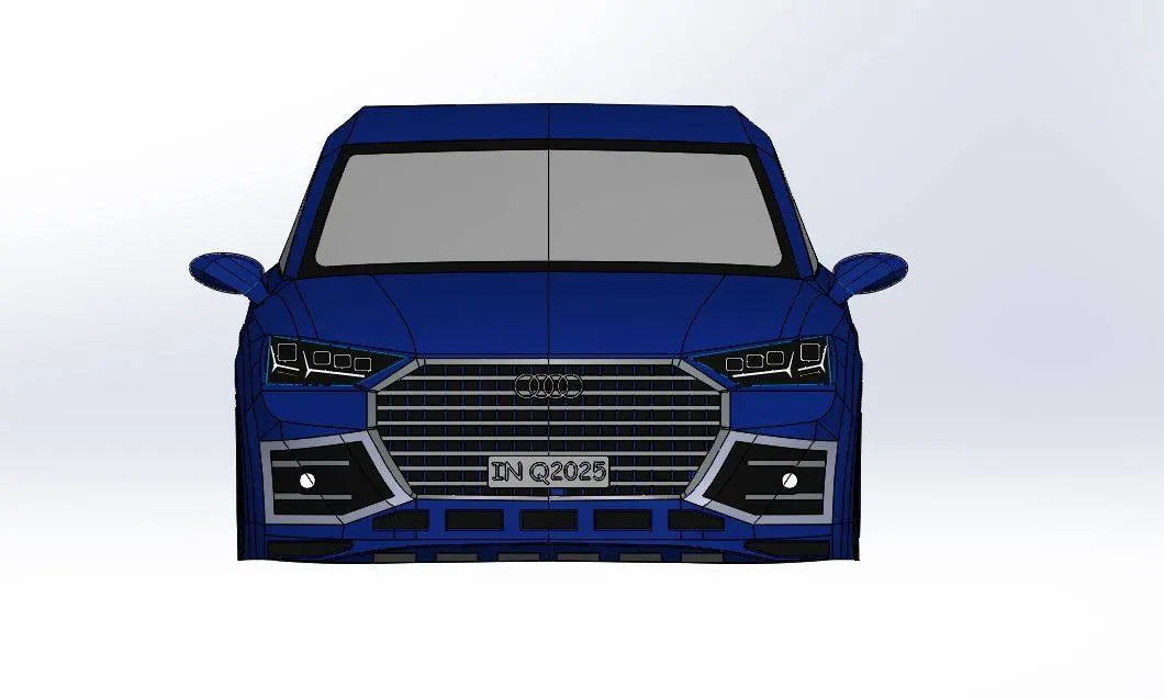
Front View -
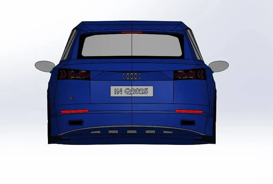
Rear view -
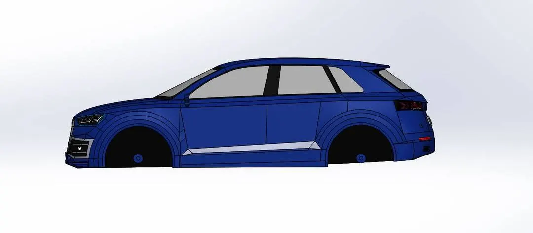
Side view -
Top view -
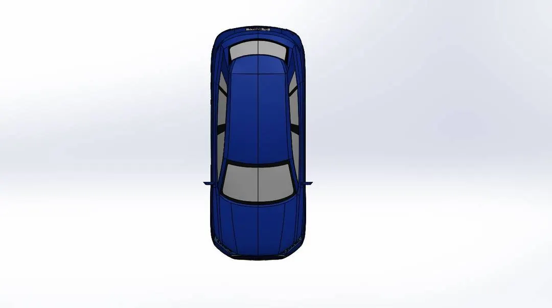
6. Assembled model –
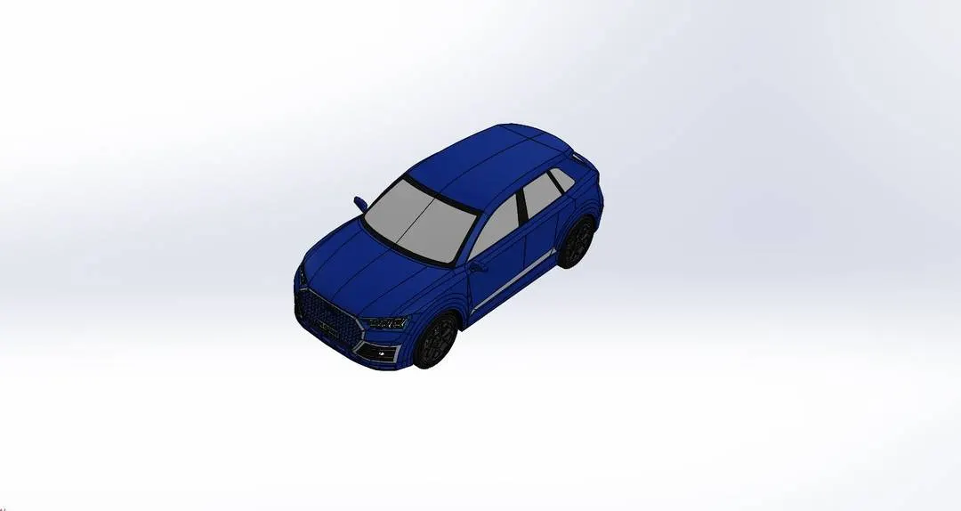
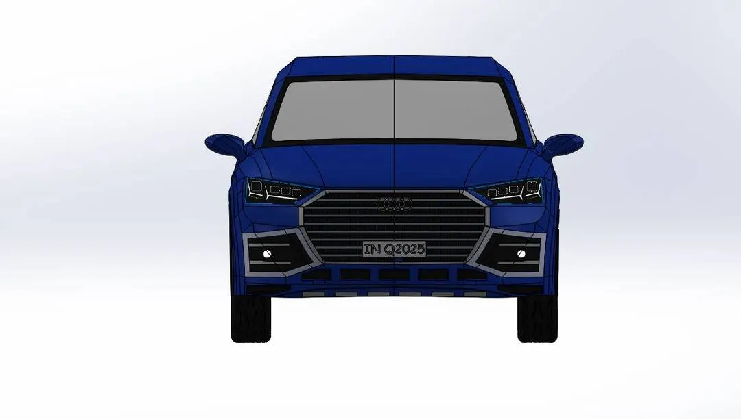
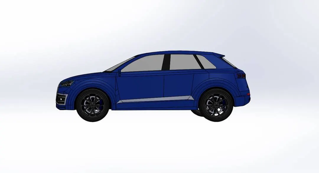
We used Solidworks assembly feature to assemble car. Co-centric and coincident mates are use to assemble rim and tire, caliper and brake rotor into one piece and then wheel is assembled to vehicle body with again, co-centric and coincident mate.
Isometric view –
Front view –
Side view –
Top view –
Camera view –
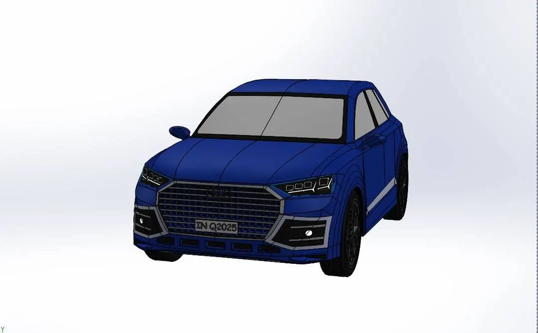
Animation -
7. Rendering images –
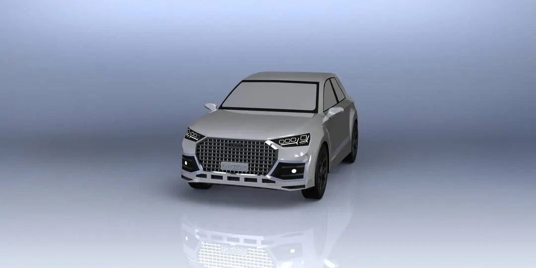
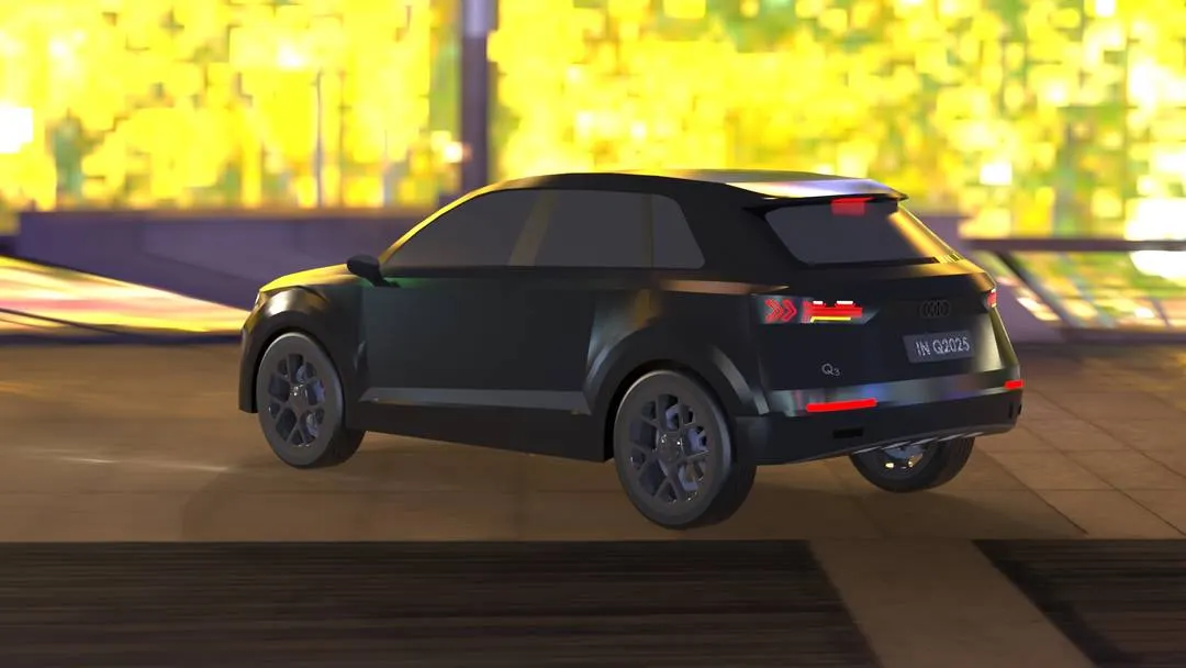
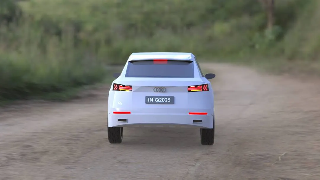
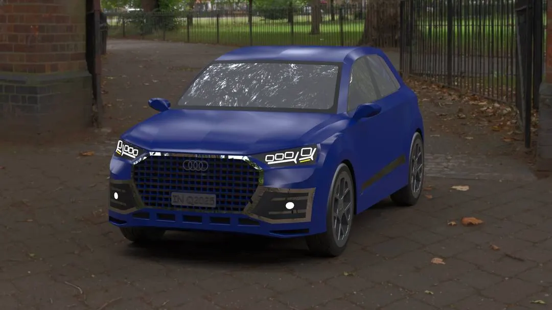
Rendering is a process of generating a photo-realistic image by means of computer software. For photorealistic rendering we used both photoview360 and Solidworks visualization.
Wheel
Environment - Blurred studio
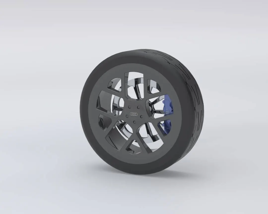
Environment - Blurred studio
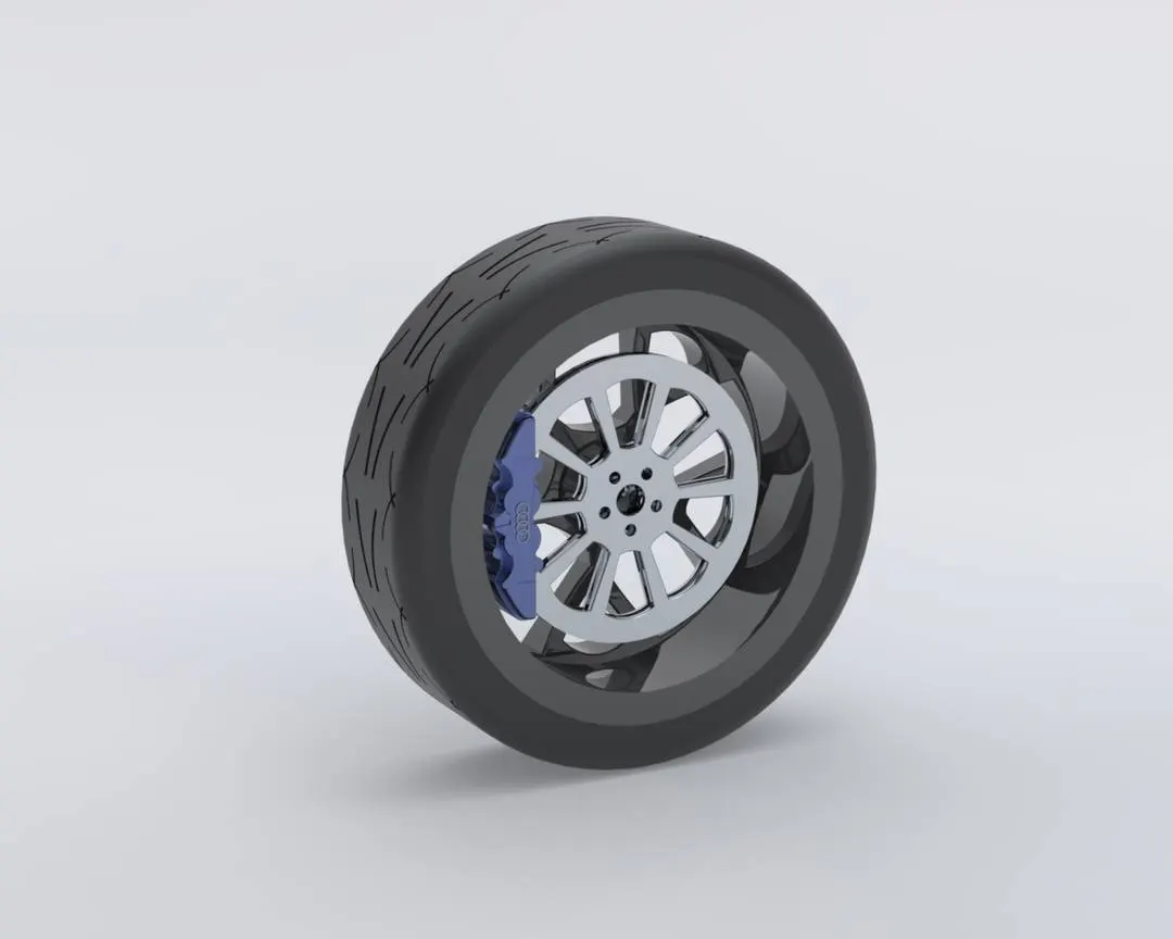
Assembled model
Environment - 3-point beige
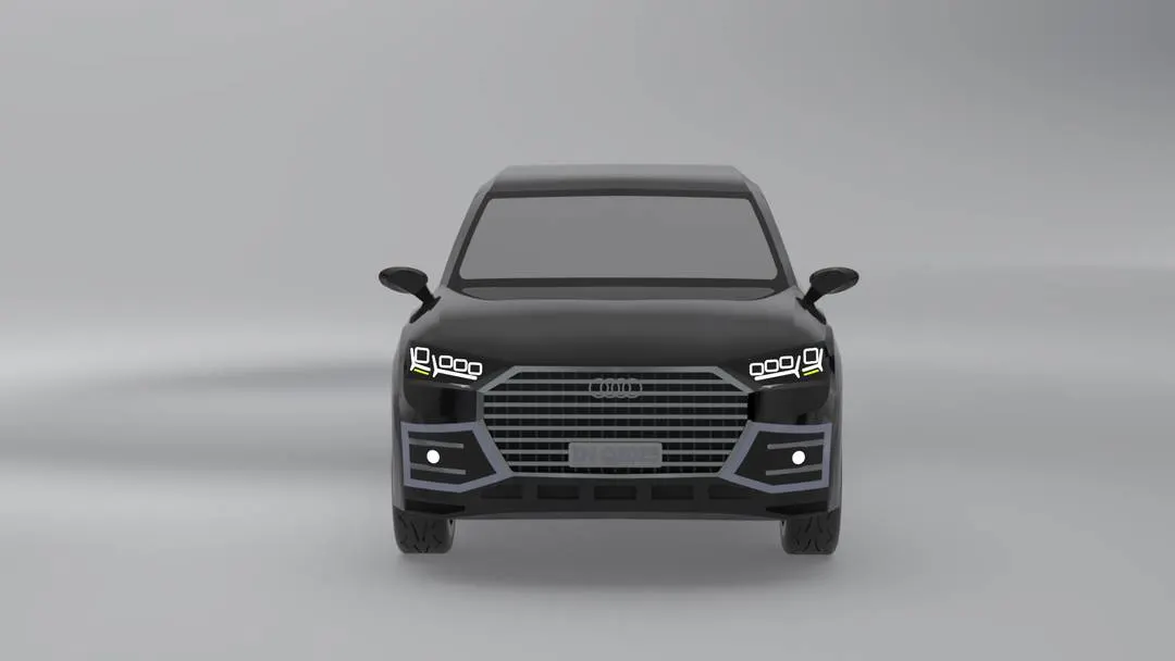
Environment - Studio room
Environment - Shangai bridge
Environment - Dam road
Environment - Bethnal green entrance
8. Conclusion – it’s been an exciting journey through out the project. Car is assembled after modelling necessary parts. Some of the part gave me lots of challenges but some reference gave me power to overcome. But journey has begun to step in automotive design world and ready for exciting challenges.