Week 5 Battery characteristics using drive cycle
Study – Simulate generic battery model charge discharge using UDDS data.
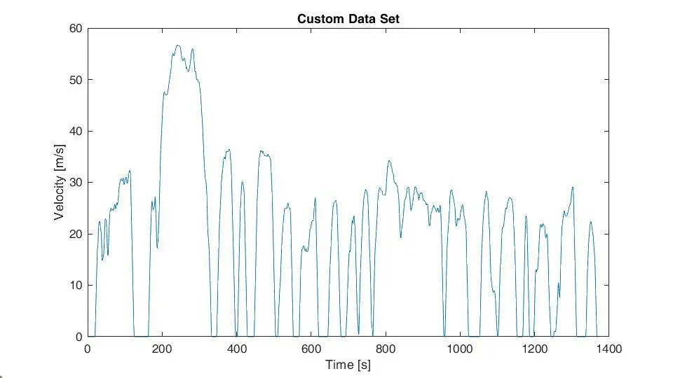
Drive cycle is data set of velocity versus time. In this particular we are using Urban Dynamometer Driving Schedule (UDDS) or Federal Test Procedure (FTP72). It has 1369 seconds for different velocity points. Driving cycle are produced to assess the performance of vehicle like by finding fuel consumption, emission and some thermal parameters also. In this study we are using drive cycle to find charge and discharge characteristics of li-ion battery in Simulink.
Model description -
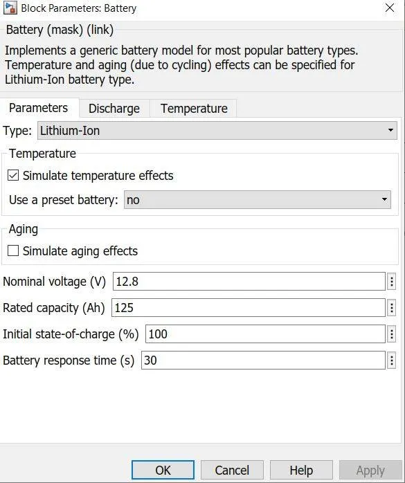
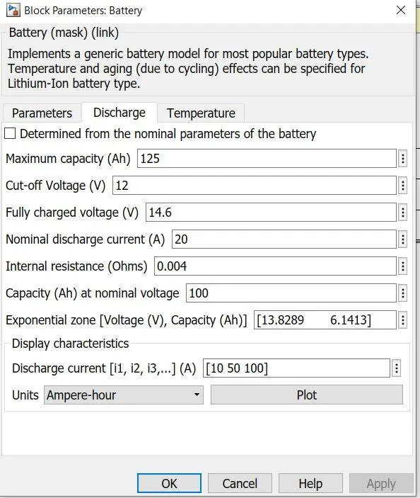
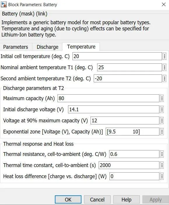
Simulink allows to choose battery model which can be configured with many parameters and even types of battery also. We chose li-ion battery with 125Ah capacity. Capacity has been kept little high, so it can bear range of drive cycle.
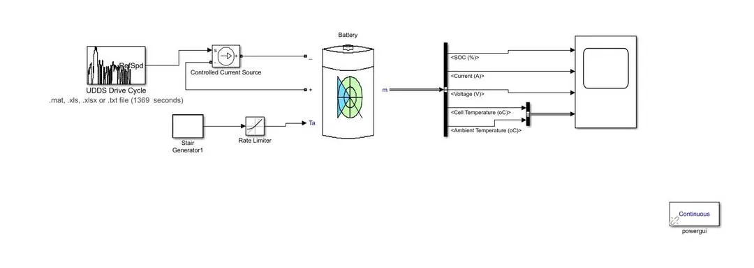
Blocks used –
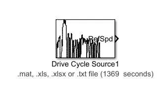
Drive cycle source – it generates longitudinal drive cycle. For this project we are importing data of UDDS cycle from an excel file.
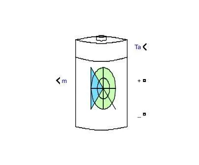
Battery – this block implements equivalent circuit model of battery. It provides four battery types -lithium-ion, lead-acid, nickel-cadmium and Nickle-metal-Hydrite. This particular block can be modelled with aging and temperature effects. We modelled with it with temperature. Battery has three input terminals, two of them are connected with controlled current source and third one is reserved for ambient temperature values. It gives series of information as output, which can be used by bus selector.
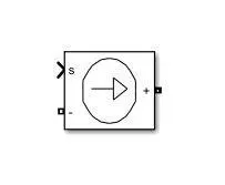
Controlled current source – this block converts input signal into equivalent current signal. In this model it is converting drive cycle data into current signal, which is further fed to battery block.
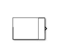
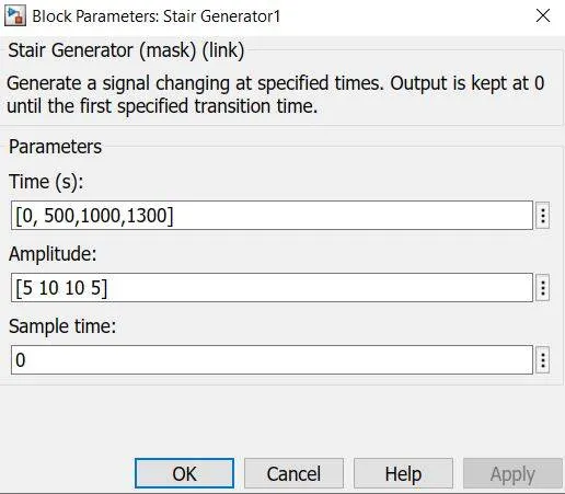
Stair generator – this block generates stair signal based on amplitude and time. In this model we are using it to give temperature values at some specific time values.
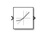
Rate limiter – this block limits the rate of signal, in this study it is limiting temperature signal.
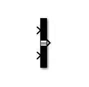
Bus selector – this block allows us to select signal from the pile of information, which is the output of battery block.
Bus creator – it creates bus from input signals. In this model we used it to create a bus of ambient temperature and battery temperature.
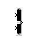
Scope – it displays generated signals.

Result –
Battery used for this has high capacity because UDDS drive cycle is quite big. Now look at the figure, SOC % is clearly depends on the velocity, around 200 second velocity is raising and it attains maximum value of 56, here SOC is decreasing with a steep rate.
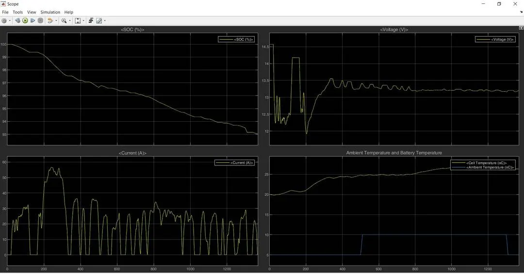
Current values are imitating drive cycle data and voltage starts with 14.6V and decreases as vehicle moves on. Now look at battery temperature and temperature, when ambient temperature changes from 10 to 5, battery temperature rate is decreasing.