Project - 2 - Meshing on the suspension Assembly
Study - For the given assembly, check for the geometrical errors and mesh with the given element Quality criteria. After meshing the component the thickness has to be assigned for mid surfaces. Use tetra elements to model non-uniform thickness components. Also use connections to connect the component.
Common Note:
- Use Volume mesh for Tyre and Rim with below Quality criteria. (Use Tria Element)
- Use mid surface only when the thickness is uniform and less than 5 mm. (Use Mixed elements)
Quality Criteria for Tria Elements (Tyre and Rim):
|
S.No |
Quality Criteria |
Value |
|
1 |
Target/Average length |
6.5 |
|
2 |
Minimum Length |
5 |
|
3 |
Maximum Length |
10 |
|
4 |
Skewness |
45 |
Quality criteria for Mixed elements (For Midsurface only):
|
S.No |
Quality Criteria |
Value |
|
1 |
Target/Average length |
4 |
|
2 |
Minimum Length |
2 |
|
3 |
Maximum Length |
6 |
|
4 |
Aspect |
3 |
|
5 |
Warpage |
15 |
|
6 |
Skewness |
45 |
|
7 |
Jacobian |
0.7 |
|
8 |
Minimum Quad Angle |
45 |
|
9 |
Maximum Quad Angle |
135 |
|
10 |
Minimum Tria Angle |
30 |
|
11 |
Maximum Tria Angle |
120 |
Quality criteria for Tria (For other components):
|
S.No |
Quality Criteria |
Value |
|
1 |
Target/Average length |
4 |
|
2 |
Minimum Length |
2 |
|
3 |
Maximum Length |
6 |
|
4 |
Skewness |
45 |
Common Quality Criteria for Tetra elements are:
|
S.No |
Quality Criteria |
Value |
|
1 |
Tet-collapse |
0.2 |
All the elements in your model should clear the above-mentioned quality criteria and the features in the model have to be captured properly with good mesh flow.
1. Title – Meshing and Connection of Rear Wheel Assembly
2. Objective -
- To import CAD model of rear wheel assembly and perform geometry clean up.
- To generate mid surface as per minimum thickness and mesh it with quads.
- To generate mesh with trias on higher thickness components and generate volume.
- To generate tetra mesh on generated volumes and apply some connections.
3. Introduction –
ANSA is an advance multidisciplinary CAE pre-processing tool that provides all the necessary functionality for full model build up, from CAD data to ready to run solver input files, in a single integrated environment. ANSA is user’s preference due to its wide range features and tools that meet their needs. The data management capabilities and the large number of supported solver and disciplines enables unique multivariant modelling implementation. ANSA has many benefits like handles data efficiently, reduces significant time, increases quality, reduces error prone user operations etc.
4. Procedure –
In this project we are going to generate mid surface for the component which has thickness less than 5mm and mesh it with some quality criteria. Tria mesh will be applied on the thicker parts and later tetra mesh will be generated from trias. At the end of the project, we are going to apply some connection to represent bolt and welding connections. We have to stick with the procedure and For this we have to follow the following steps –
1. First, import the CAD model using option open from file menu.
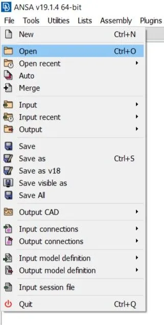
Fig. Importing CAD Model
2. Perform topology using topo option and Run check geometry option and look for errors like over lapped faces, unchecked faces, cracks etc.
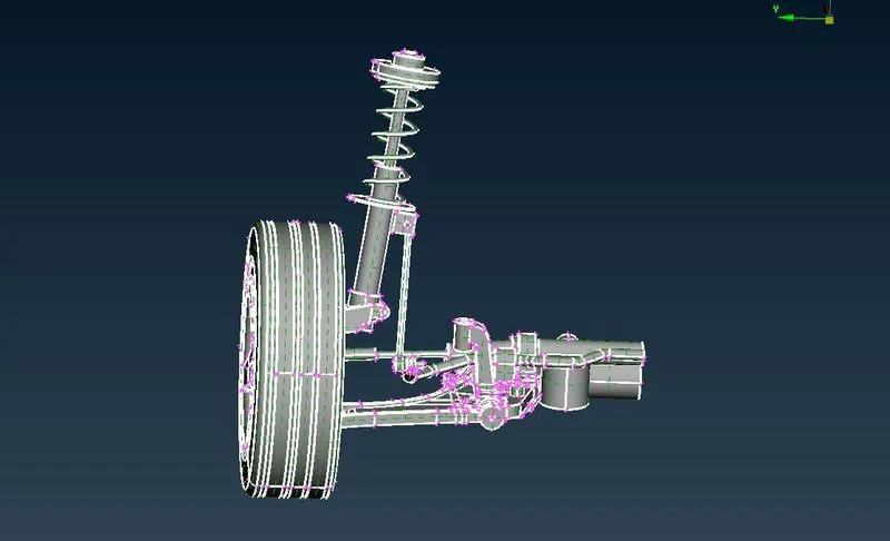
Fig. Performing Topology
3. Auto fix the faults using auto fix option of ANSA. Remaining faults can be solved manually. Run geometry check again it is indicating a green, means we can proceed.
4. Off the visibility of parts except rim, from property menu.
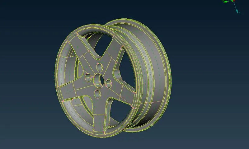
Fig. Rim
5. Set mesh parameters and quality criteria.
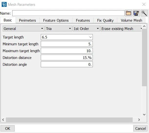
Fig. Mesh Parameter for Rim and Tyre
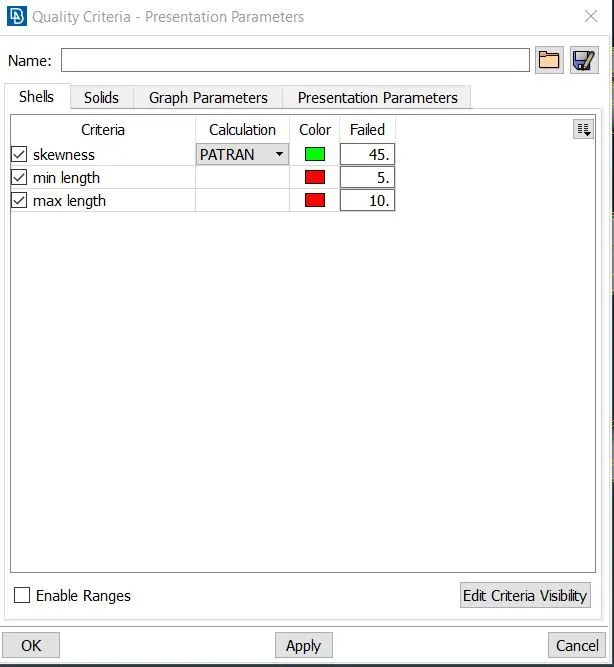
Fig. Quality Criteria for Rim and Tyre
6. Deploy tria mesh. On the curved area ortho tria mesh can be deployed used. Look for off elements and remove them, without disturbing fundamental structure of rim.
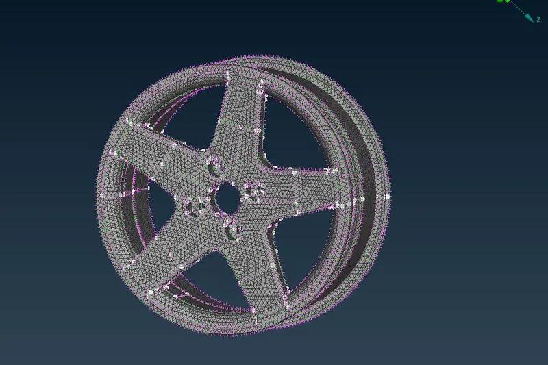
Fig. Meshed Rim
7. Now, go to volume mesh deck and use option define under volume menu to define volume of visible part. Generated volume can be checked in volume list using list option under volume.
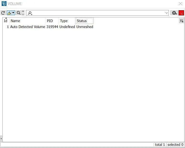
Fig. Volume List
8. List will show type undefined and status as unmeshed. Set solid quality criteria collapse as 0.2.
9. Use either of tetra rapid of tetra fem to generate tetra mesh. Remove off elements, fix quality under improve menu can be used for it.
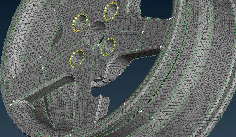
Fig. Rim with Tetra Mesh
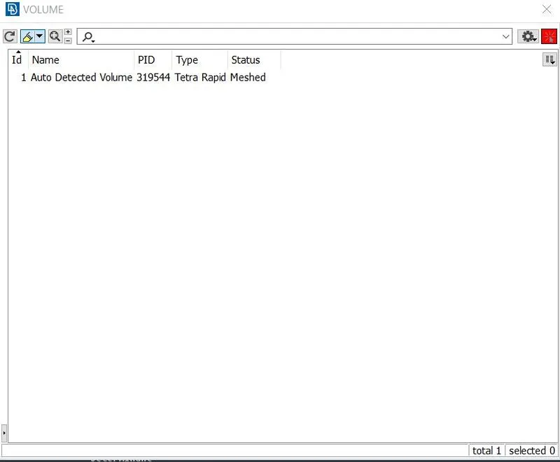
Fig. Volume List after Meshing
10. Similar procedure can be repeated for tyre.
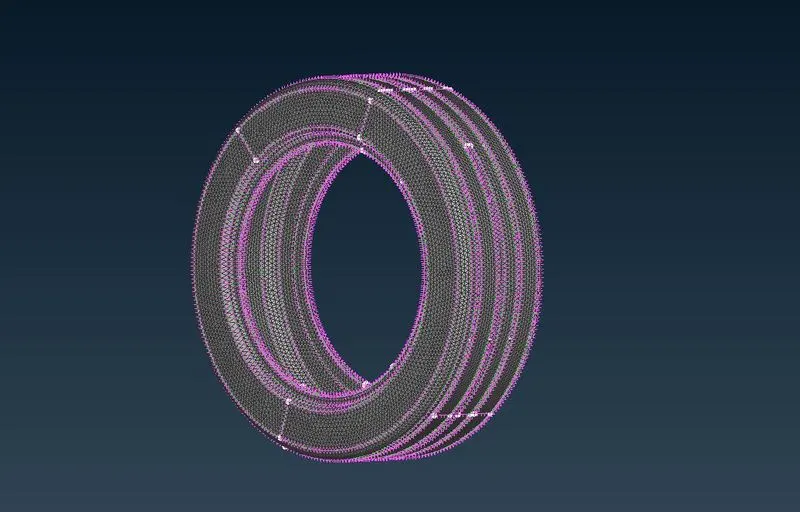
Fig. Tyre with Tria Mesh
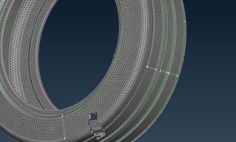
Fig. Tyre with Tetra Mesh
11. Detect other parts which has thickness less than 5mm and generate mid surface.
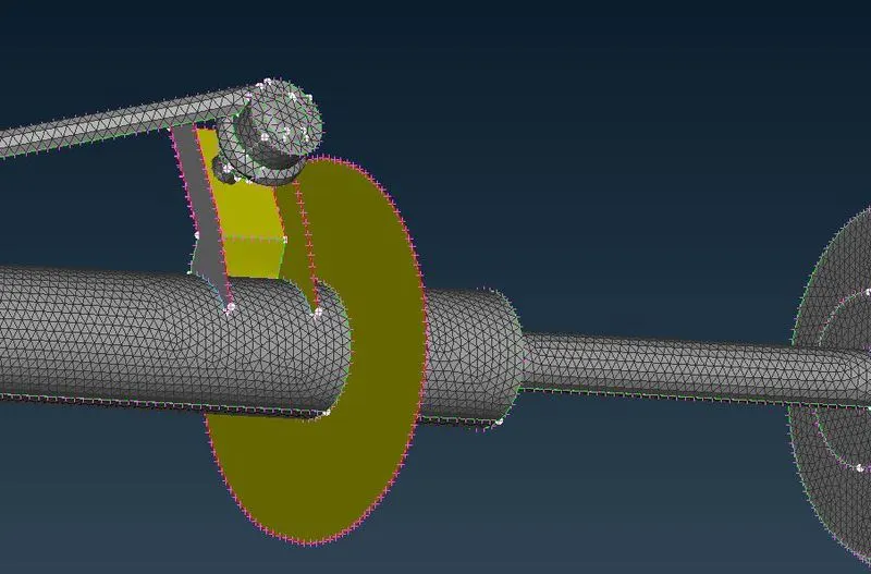
Fig. Generated Mid Surface
12. Set quality criteria and mesh parameters.
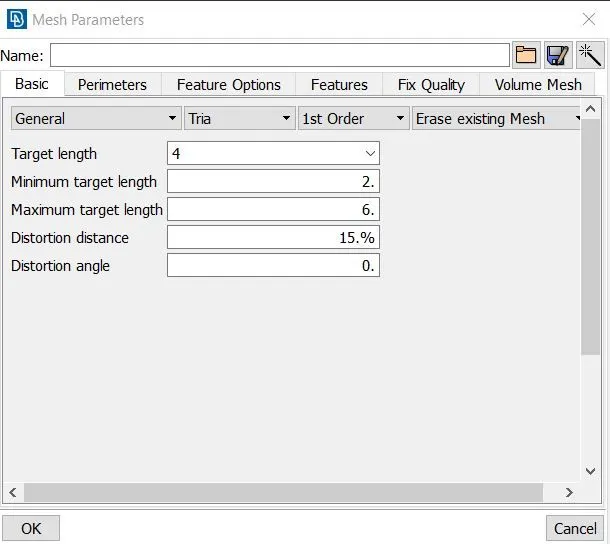
Fig. Mesh Parameters for Remaining Parts
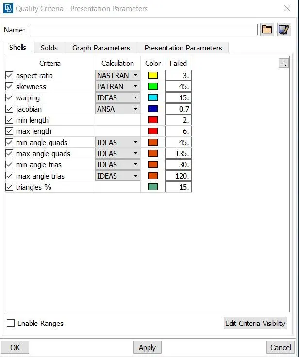
Fig. Quality Criteria for Parts(Thickness<5)
13. Generate mesh quad mesh and remove off elements. Inspect model carefully look for the unmeshed parts if any.
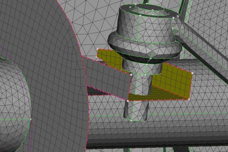
Fig. Quad mesh on Mid Surfaces
14. Look for remaining components and Deploy tria mesh and remove necessary off elements. If off element is affecting structure, then they can be left.
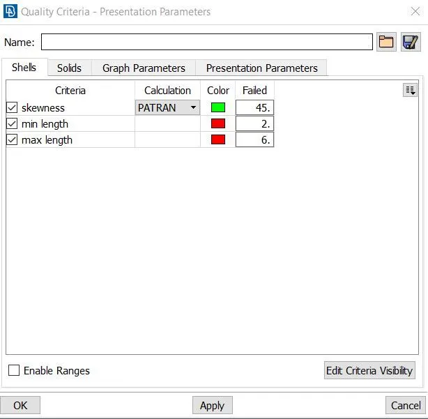
Fig. Quality Criteria
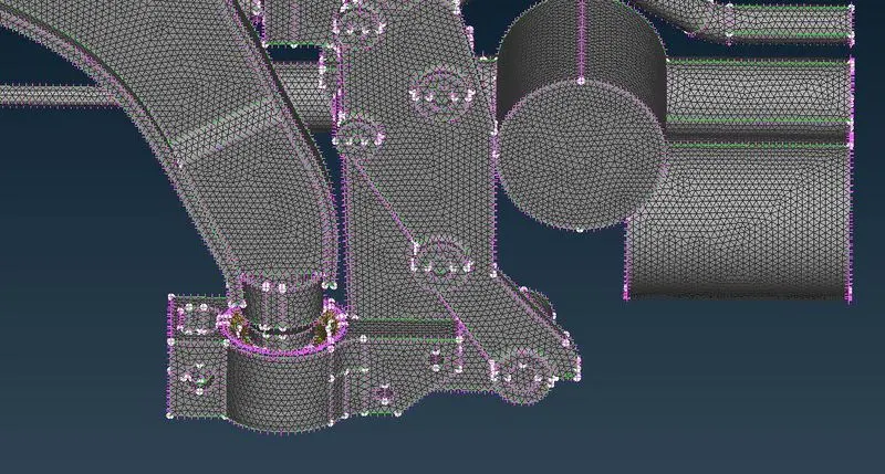
Fig. Component with Trai Mesh
15. Generate volume and use tetra mesh or tetra fem to generate volumetric mesh.
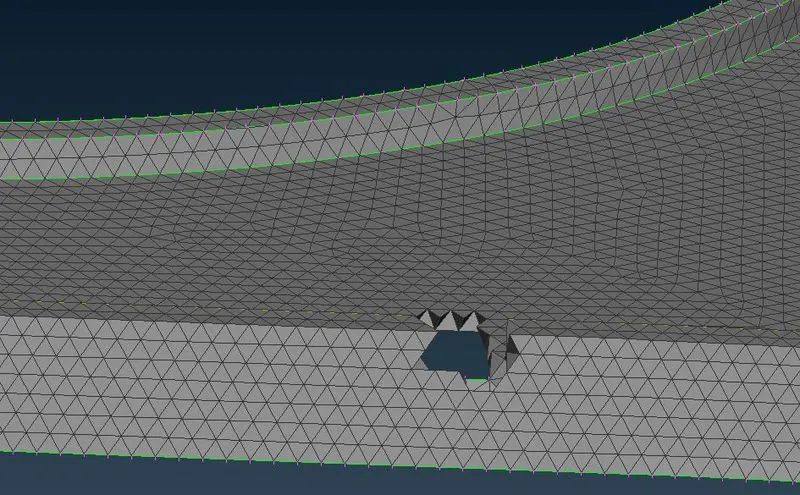
Fig. - Component with Tetra Mesh
16. Identify sites for connection and go to Nastran deck.
17. Select RBE2 many node option, it will ask for slave node and master node, select them carefully. It will create representation of bolt. On the other side part similar representation can be created. Now, click on option RBE2 two node, select master nodes of the holes, it will create a yellow line which represents bolt stem.
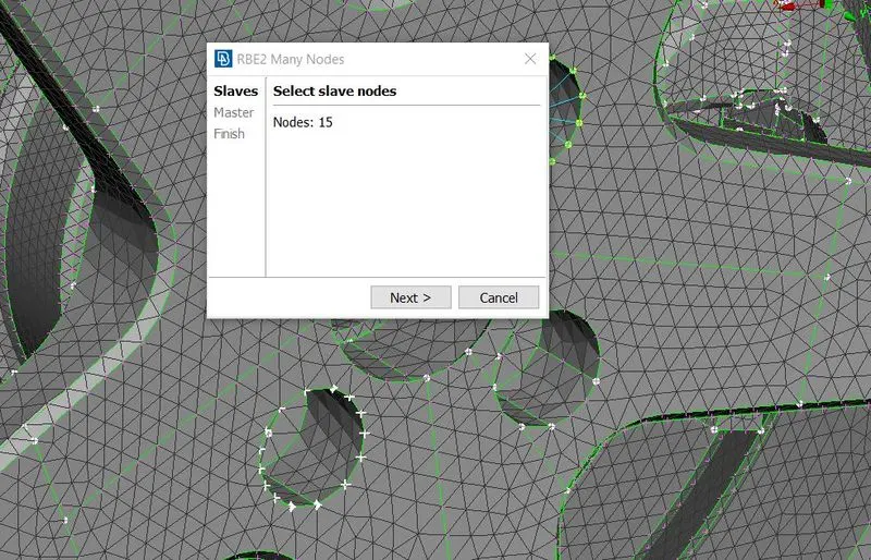
Fig. - Deploying Connections
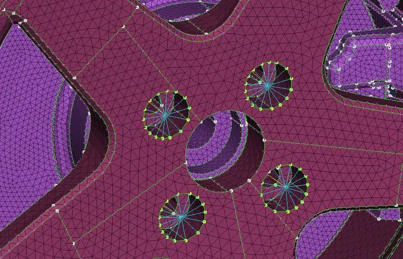
Fig. Bolt Representation
18. Other connection can be made with similar procedure as we talked in step 17. Spring element is represented with 1D bar element.
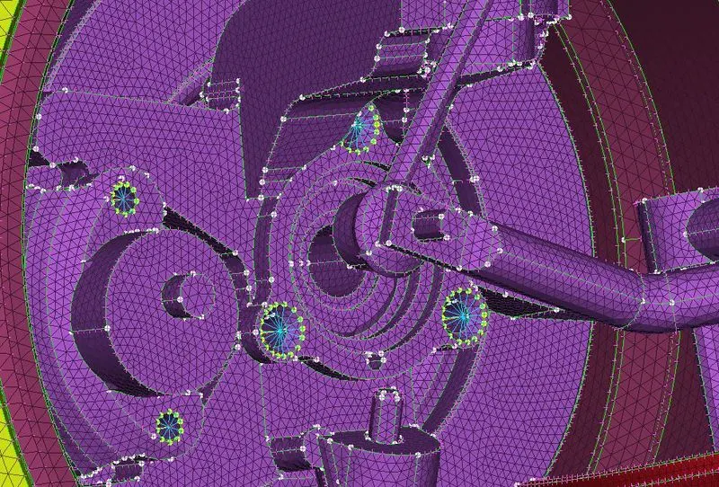
Fig. Connections
19. Generate curve at middle of the spring using middle command of curves on topo deck.
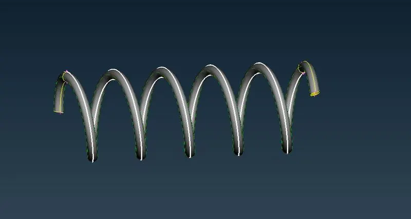
Fig. Generating Middle Curve
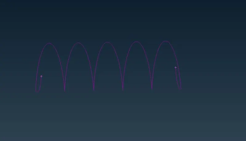
Fig. Middle Curve
20. Generate a centre of gravity point by selecting the curve, which we crated by spring. Go to Nastran deck and select cbar option, it will redirect you to property menu. Generate new property and go to input box under A and press shift and ? together to assign parameters. Put the value of radius as 5mm and press ok. It will calculate other parameters like area, moment of inertia etc. automatically.
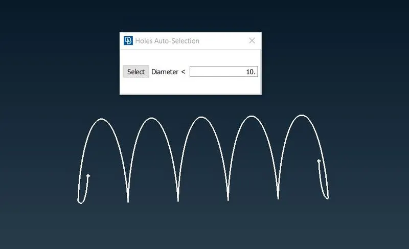
Fig. Generating C.O.G.
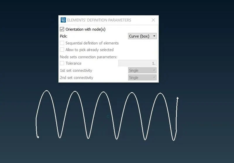
Fig. Defining Element Parameter
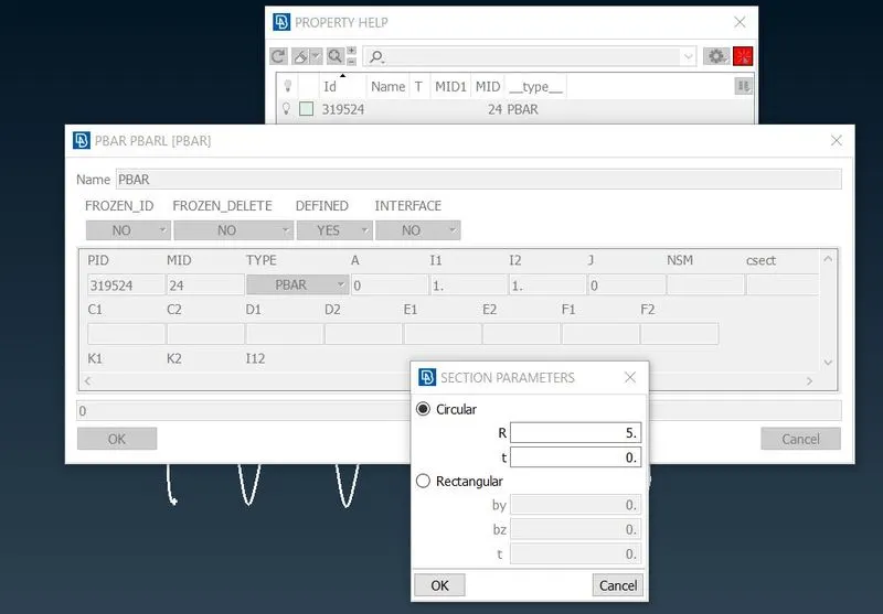
Fig. Defining Properties of Bar Element
21. 1D bar is represented with a curve with repeated 1-2-3 written on it. To see it’s 3D representation, go to quality criteria-presentation parameter and enable line elements cross section by selecting as solids.
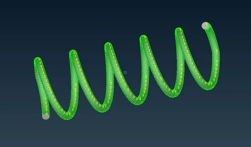
Fig. 3D Representation of Bar Element
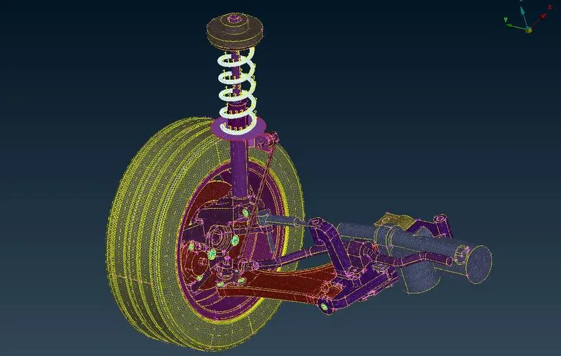
Fig. Complete Model
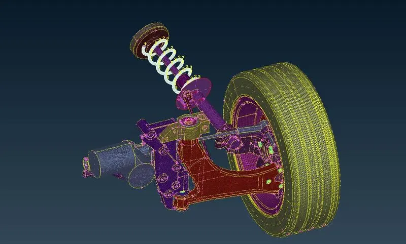
Fig. Complete Model
5. Conclusion –
ANSA is on most important pre-processor in CAE domain. It allows you to complete, modelling in a single environment and put your data to work achieving seamless modularization. ANSA provides all the modelling tools we need and eliminates tedious tasks trough automation. ANSA allows you to complete our work for any discipline and any major solver through the uniquely interoperable processing decks. In this project we explored some unique features of ANSA to achieve best model, which is ready for ANSA supported solvers. Model is prepared with tetra mesh, quad mesh where parts where thin and connections for bolt representation.
Model - https://drive.google.com/file/d/1xbAAcHbMgLcOmzBBZuFcXeSU9Wp4smjl/view?usp=sharing