Photo Realistic Rendering
1.Title – Modelling and Rendering of American Chopper.
2.Objective –
- Design and modelling of components of American chopper in Solidworks, using sketch tools and 3D modelling features.
- Assembly of American chopper using Solidworks assembly tool.
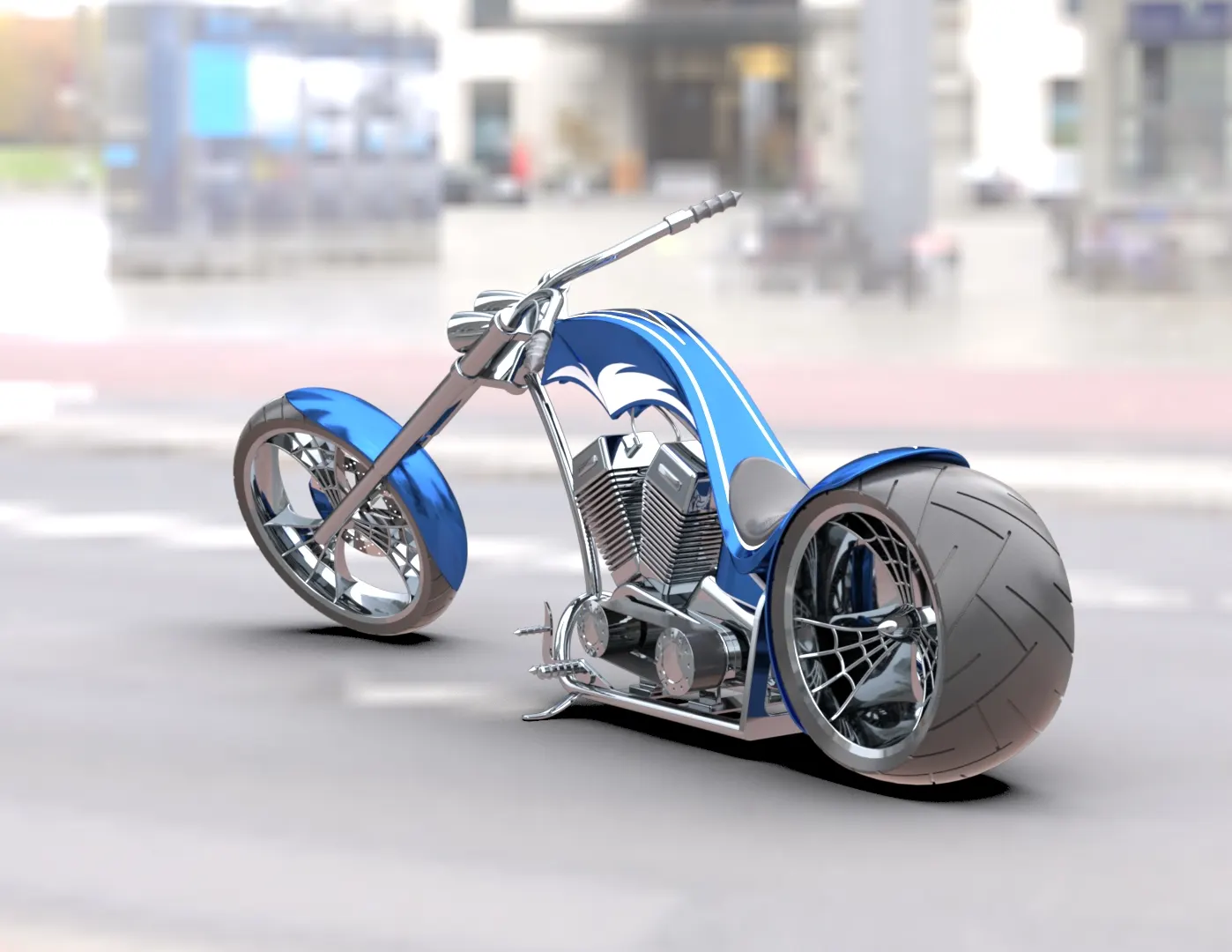
- Rendering images of American chopper using Photoview360 and Solidworks visualization with different environments and views.
3.Introduction –
Chopper is a motorcycle, that’s original parts are replaced with custom parts, so it is called as custom motorcycle or bike also. Generally chopper motorcycle described as low to ground, usually with extended forks, frames without rear suspension, stretched frames and very short handlebars.In this project we are going to use Solidworks software with its handy features to model components, assembly of the components and will create photo realistic images using rendering tools.
4.Design methodology –
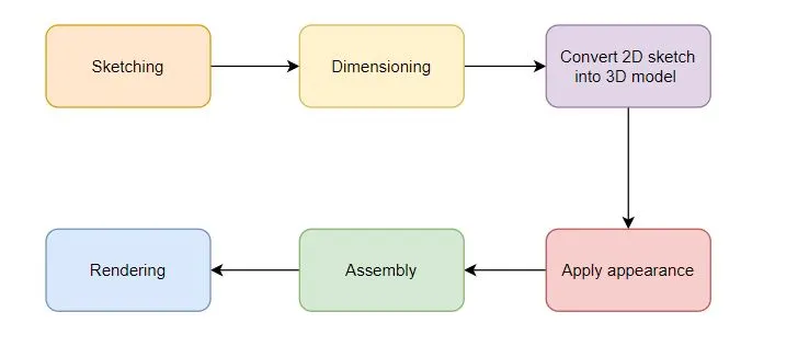
5.Description –
Modelling involves a representation of something like a functioning volcano, a car, etc. modelling has various applications. consider a motorcycle. It has hundreds of components. Each component can be modelled separately and can be assembled together to get final form of motorcycle. This type of modelling is called as part modelling.
The following parts are modelled –
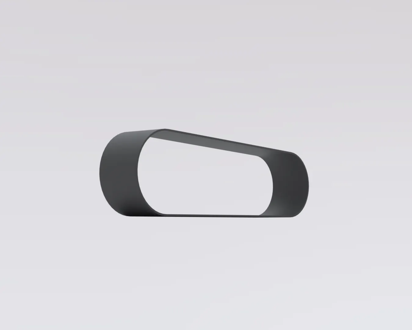
Transmission Belt
Transmission belt transfers the power from engine to gear box. It mounted on respective pullies of engine and ger box.
Features used – Boss extrude and Fillet
Modelling procedure –
- Start with sketching two inline circle with diameter according to engine pulley and gear box pully.
- Join circle using line and trim unnecessary arcs and by giving shape as belt.
- Apply boss extrude feature and extrude it considering the thickness of belt.
- Apply matte rubber appearance and some fillets for finishing.
Kick stand
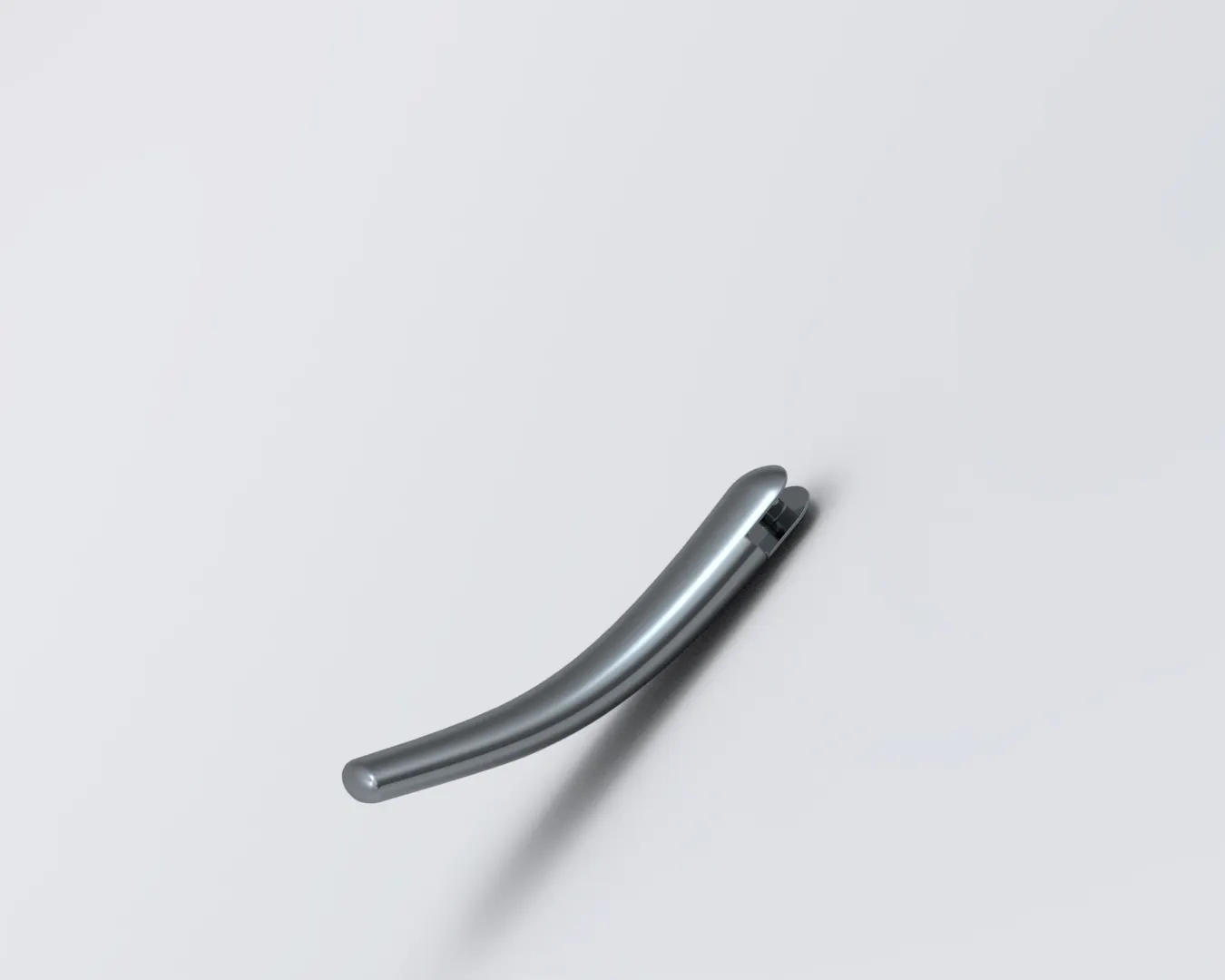
Kick is a component chopper, which allows motorcycle to stand upright without leaning on other object.
Features used – Boss extrude, Fillet, Dome, Cut extrude, Loft and Split.
Modelling procedure –
- Start with sketching two circle which are connected with an arc.
- Now use loft feature to add material between circles following arc as a path.
- Apply domes at the both the end and use cut extrude to make some part flat of the end which will stick to ground.
- Use split command to consume unnecessary part which was made by extrude cut.
- Sketch for the pivot and extrude it using boss extrude feature.
- Apply fillets and appearance.
Rear fender
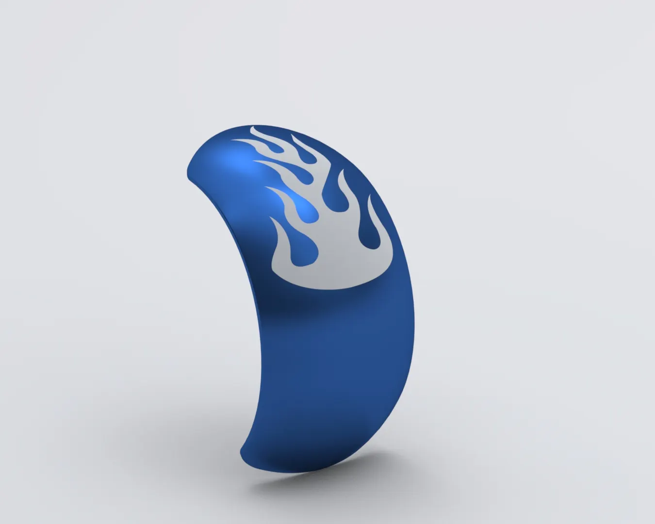
It is a component of vehicle which frames a wheel and prevents it from mud, rocks and other road spray from being thrown into the air by tire. Fender mounted for rear wheel called rear fender.
Features used – Revolve, Split, Shell, Fillet.
Modelling procedure –
- Start with sketches for revolve and reference on vertical plane.
- Use revolve feature to revolve curve and give shape as fender.
- Use split command to remove some portion at the end of fender and Apply some fillets.
- Now use shell command to hollow it and apply siena as appearance colour.
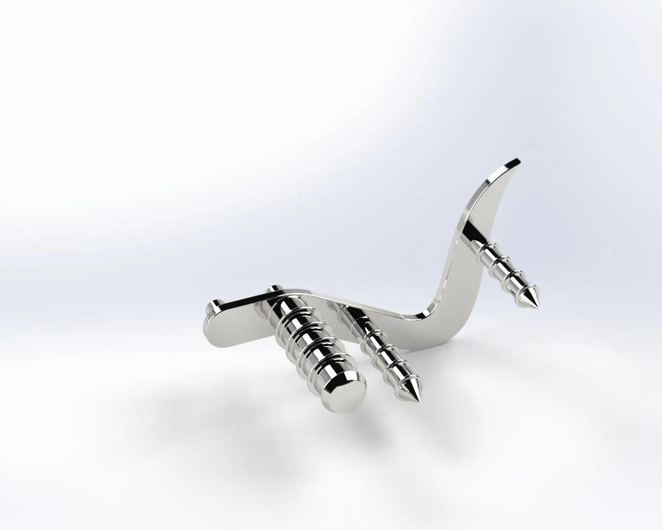
Pedal
Pedal is a foot operated lever used to control certain mechanism in chopper.
Features used – Boss extrude, Fillet, Dome, Revolve, Chamfer and Linear pattern.
Modelling procedure –
- Start with making sketches of pedal and pivot point on front plane and extrude them.
- Apply some fillets to remove sharp edges and make rectangle on boss extruded part one.
- Use revolve feature and revolve rectangle which ends ups with a cylinder. This is the part Where foot will rest during riding.
- Now decorate foot mounting with some integrated disk which will hold foot firmly on pedal and apply appearance.
Chain
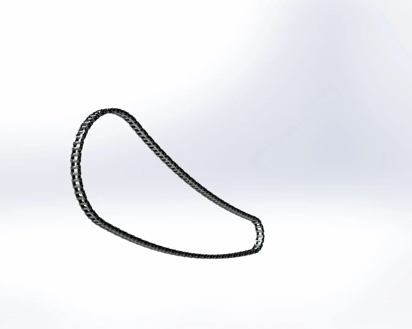
Chain is power transmission device, which transfers the power from gear box to rear wheel in chopper.
Features used – Boss extrude, Fillet, Circular pattern and Body-delete/keep.
Modelling procedure –
- Start with sketching a guiding curve which will be followed by chain blocks.
- Sketch plates and pins and extrude them. Make block of the inner and outer pins sketch. These sketches can be used anywhere in the modelling. Apply some fillet.
- Now make curve driven patten for pins and plates which follows guiding curve.
- Apply circular pattern to model chain at the circular end of chain.
- Use mirror feature to mirror inner and outer plate with reference to mid plane and apply appearance.
Oil tank
Oil tank stores fuel in chopper.
Features used – Boss extrude, Fillet, Shell and combine.
Modelling procedure –
- Start with sketching the base of oil tank on the top plane and extrude it.
- Make sketch on mid plane which will define height of oil tank.
- Use combine feature to get common part of base and height extude.
- Apply fillets and put elegant colour for appearance.
- Use shell command to make oil tank hollow.

Front Fender
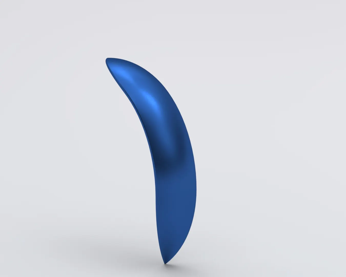
Fender which frames the front wheel of chopper called front fender.
Features used – Boss extrude, Fillet, Shell and revolve.
Modelling procedure –
- Sketch a set of arcs closed with line, which will define the shape of fender.
- Revolve sketch to get 3D model of fender.
- Use split command to remove unnecessary portion at end of the fender.
- Apply fillet and pleasant appearance.
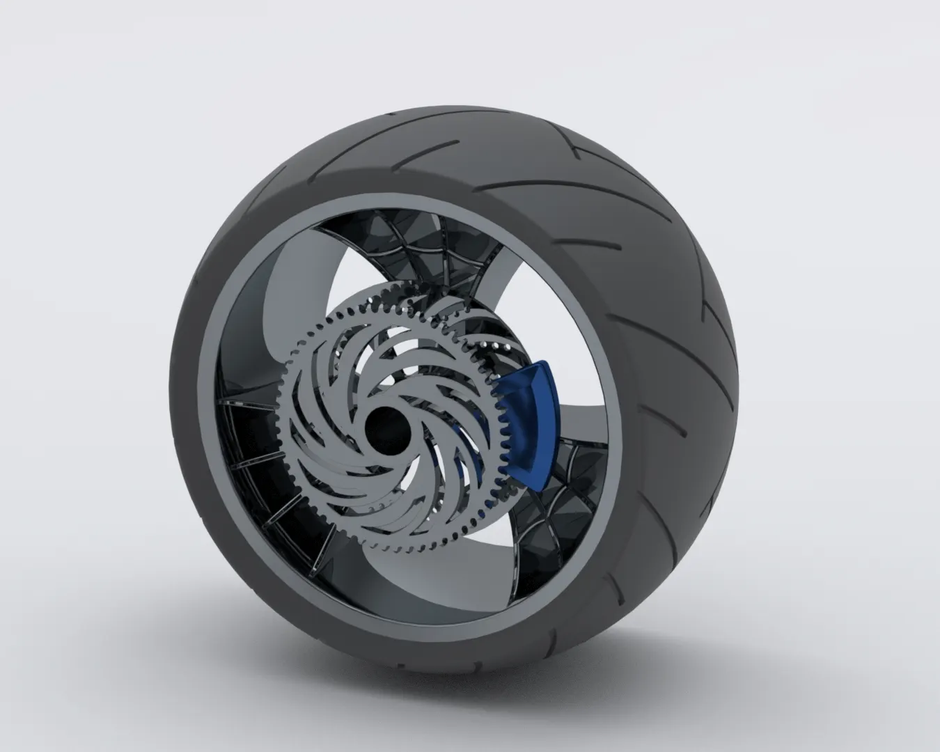
Front wheel
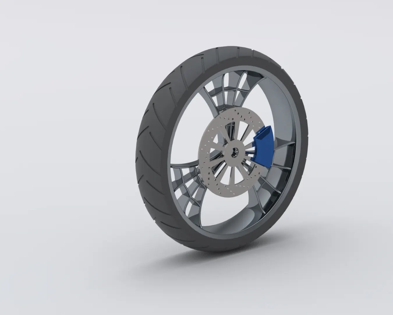
Wheel is circular object, which moves chopper.
Features used – Boss extrude, Fillet, Cut extrude, Revolve, Combine, Chamfer and circular pattern.
Modelling procedure –
- Sketch for barrel and reference at centre, on front plane. Convert sketch into 3D using revolve command.
- Now sketch for spokes on right plane and decorate it spider web using features boss extrude and cut revolve.
- Now use circular pattern to three instances of spoke and apply some fillets.
- Combine spokes with rim. Now sketch a circle for rotor and decorate it with some patterns.
- Sketch on face of rotor to extrude for caliper brake.
- Now sketch on barrel for tyre and revolve it. Draw sketch on tyre for treads and pattern circularly after using extrude cut.
- Apply elegant appearance.
Rear wheel
Rear wheel moves the chopper, mounted at rear side of chopper.
Features used – Boss extrude, Fillet, Cut extrude, Revolve, Combine, Chamfer and circular pattern.
Modelling procedure –
- Start sketching on front plane for rotating part of rim and revolve it to get 3D model.
- Now model spider webbed spokes using feature cut extrude and boss extrude.
- Pattern three instances of spoke and decorate with revolve cut.
- Now make sketch for part where wheel will be connected to chassis, after converting it into 3D put a dome at one end.
- Now start sketching on right plane for rotor, Extrude it and decorate with some patterns using features cut extrude.
- Make sketch on face of rotor for caliper, extrude it and apply some chamfer to get final shape.
- Now design sprocket which is at same side of rotor. Make some pattern on sprocket to give aesthetic view.
- Make sketch at periphery of sprocket, where chain will be mounted and convert it into 3D.
- Sketch on rim, in front plane for tyre and extrude it. Make tyre tread using cut extrude and circular pattern.
- Apply appearance.
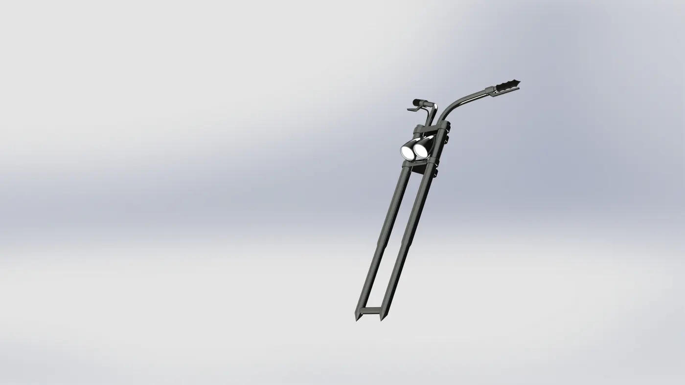
Front Fork
Front fork connects wheel and its auxiliaries to frame.
Features used – Boss extrude, Fillet, Cut extrude, Revolve, Combine, Mirror, Projecting curve and Sweep.
Modelling procedure –
- Start sketching on front for tube and convert 2D sketch into 3D using revolve feature.
- Now make sketch on face of tube end. Convert, it into 3D. it defines the position of head lights and it holds both tubes of fork together.
- Apply some fillet and start sketching at the end of tube for holding front wheel.
- Now sketch for headlight and convert it into 3D using revolve feature. Apply dome at front of headlight which will give exact convex shape.
- Sketch two curves into front plane according to shape of handle. Project curve to get perfect shape for handle.
- Make a circle at one end of projected curve and sweep it along projected curve.
- Now make lever and pattern for holding handle using sweep, boss extrude.
- Use mirror command to mirror whole part and use combine necessary parts into a single body.
- Apply appearance and make some reference plane for better visualization of fork.
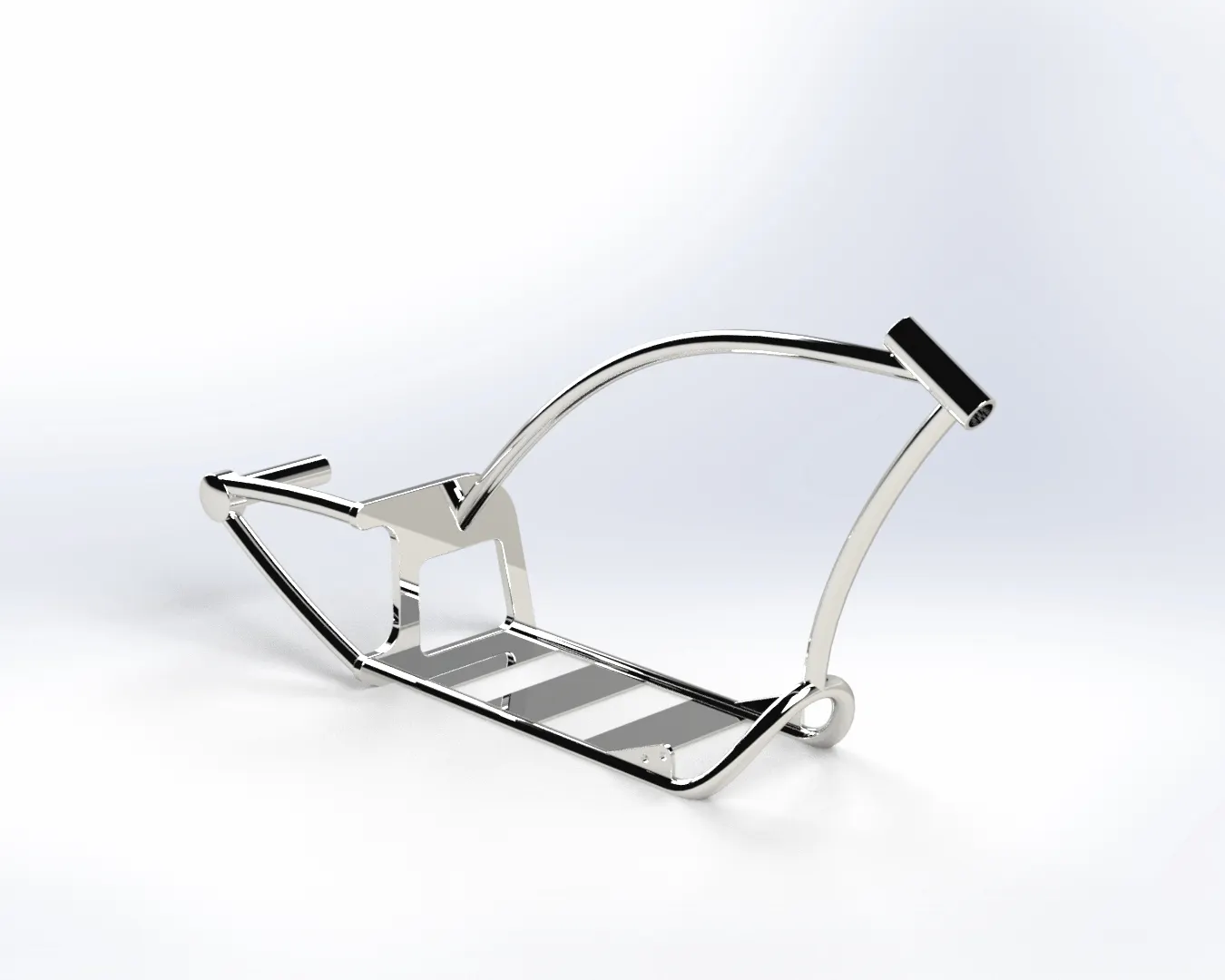
Chassis
Chassis is a frame of structure which provides support to engine, fork and wheels.
Features used – Boss extrude, Fillet, Cut extrude, Revolve, Combine, Mirror, Projecting curve, Split, Chamfer and Sweep.
Modelling procedure –
- First, Import the chopper sketch using sketch picture feature and rename of planes.
- Start with drawing curves on mid plane and bottom plane. Use projecting curve feature to combine curves into signal curve. It will give exact path of side tube of chassis.
- Make circle at the end of projected curve and sweep command to make side tube.
- Use mirror command to mirror tube. It makes base of chassis.
- Now make sketch on right plane for back portion of chassis. Use boss extrude to convert into 3D and use cut extrude to remove unnecessary potion.
- Apply some fillets on edges to remove acridness.
- Make a reference plane using mid plane and vertex of back side of chassis.
- Make sketch on newly made refence plane for tubing. These tubes joins an another tube, which will hold rear wheel.
- Now make ana curve which duplicates upper part of chassis and make a reference plane using this curve and a point at the end of curve.
- Make a circle on newly made plane and sweep it along curve.
- Make a curve which joins top and bottom potion of chassis and convert it into 3D using sweep feature.
- Make sketch on mid plane around bottom tubes of chassis. Convert these into 3D usin boss extrude feature. These will provide support to engine.
- Now make sketch on bottom tube of chassis to mount foot pedal and mirror it.
- Apply some fillets and appearance.
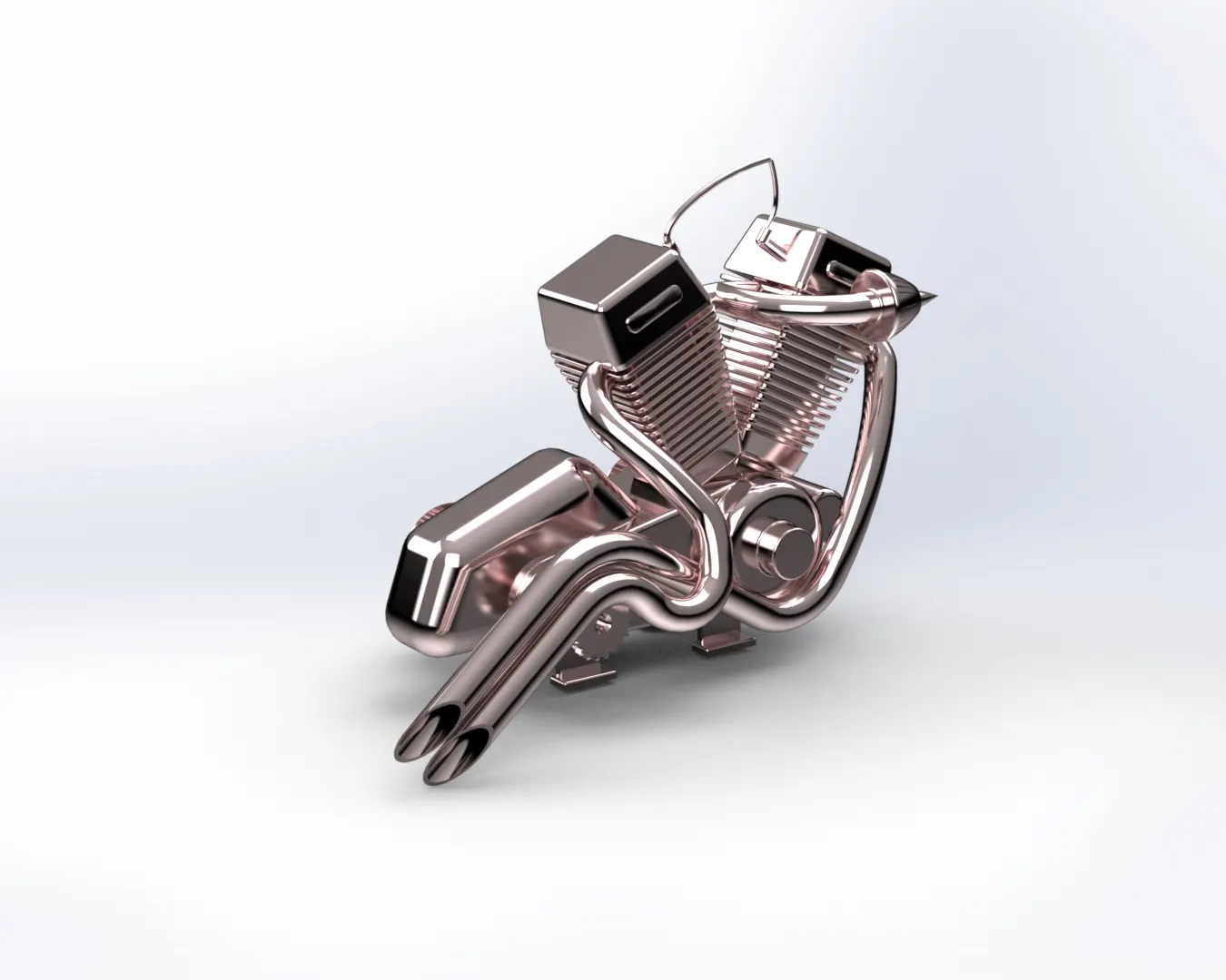
Engine
It is a power generating component which generates energy for chopper according to various demand.
Features used – Boss extrude, Fillet, Cut extrude, Revolve, Combine, Mirror, Projecting curve, Split, Chamfer, Composite curve and Sweep.
Modelling procedure –
- Start with importing sketch picture in file. Sketch circles for pullies on front plane, with some detailing.
- Extrude sketch to get 3D shape of pullies.
- Sketch for gear box on front plane, considering sketch picture as reference and use boss extrude feature to give 3D shape and apply some fillets.
- Now start sketch on right plane and sketch pullies with details like thin edges. Use revolve feature to give them, shape.
- Make a reference plane – Plane1 using right plane and vertex point at back pulley.
- Add some details on pulley, where belt will be mounted and pattern them. These will hold belt firmly.
- Apply dome on the face of pulley to give better look and apply fillets to remove sharp edges.
- Sketch on front plane for motor and extrude it.
- Make a reference line which has same inclination as cylinder has in picture.
- Now make a reference plane - plane 2 and start sketching on it for cylinder.
- Extrude sketch with draft angle which will give exact shape as V engine cylinder.
- Start sketch on plane 2 and draw some rectangles with proper dimension. Use cut extrude feature to give shape to fins and apply some fillets.
- Make linear pattern of fin, on cylinder and mirror the cylinder using right plane as reference.
- Make sketch on the bottom face of engine, where connection will be made with chassis.
- Now make a curve replicating pipe connecting both the cylinders. Draw a circle and seep it along curve and mirror it.
- Make some curve for exhaust pipe in front and on top plane. Use projecting curve to get curve exactly duplicating exhaust pipe. draw a circle and seep it along projected curve.
- Follow similar procedure for second exhaust pipe.
- Now sketch on side face of cylinder head for spark plug wire and convert it into 3D using sweep command.
- Apply elegant appearance.
Gas tank
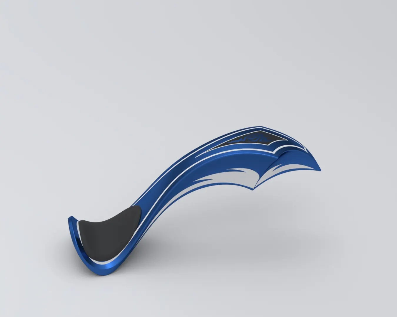
It connects seat to the chassis and accommodates spark plug wire.
Features used – Surface sweep, Surface trim, Projecting curve, Surface knit, Surface loft, Boundary surface, Surface extrude, Shell and Fillet.
Modelling procedure –
- Import the sketch picture and sketch a replicating curve on mid plane.
- Make a reference plane – plane1 using end point of curve and front plane.
- Now sketch curve on plane1 and use surface sweep to make 3D surface.
- Draw some curves on bottom plane and use it trim unnecessary surface.
- Now again make a reference plane using mid plane and end point of surface and draw some curves and project them.
- Loft the surface with loft command, which uses projected curve as path.
- Make a reference plane – plane 3 using front plane and vertex point of the back of surface.
- Sketch on plane 3 to get side portion of fuel tank after using surface extrude command.
- Mirror whole drawn part and use surface knit option to integrate whole part in one.
- Make sketch on bottom plane for seat and use split line command to split it from existing model.
- Extrude seat and apply some fillet.
- Now sketch on plane 1 for front portion of gas tank where it will be attached by chassis, loft it and remove unnecessary portion by cut sweep feature.
- Apply fillet, use shell command to make it hollow and apply appearance.
6.Assembly model –
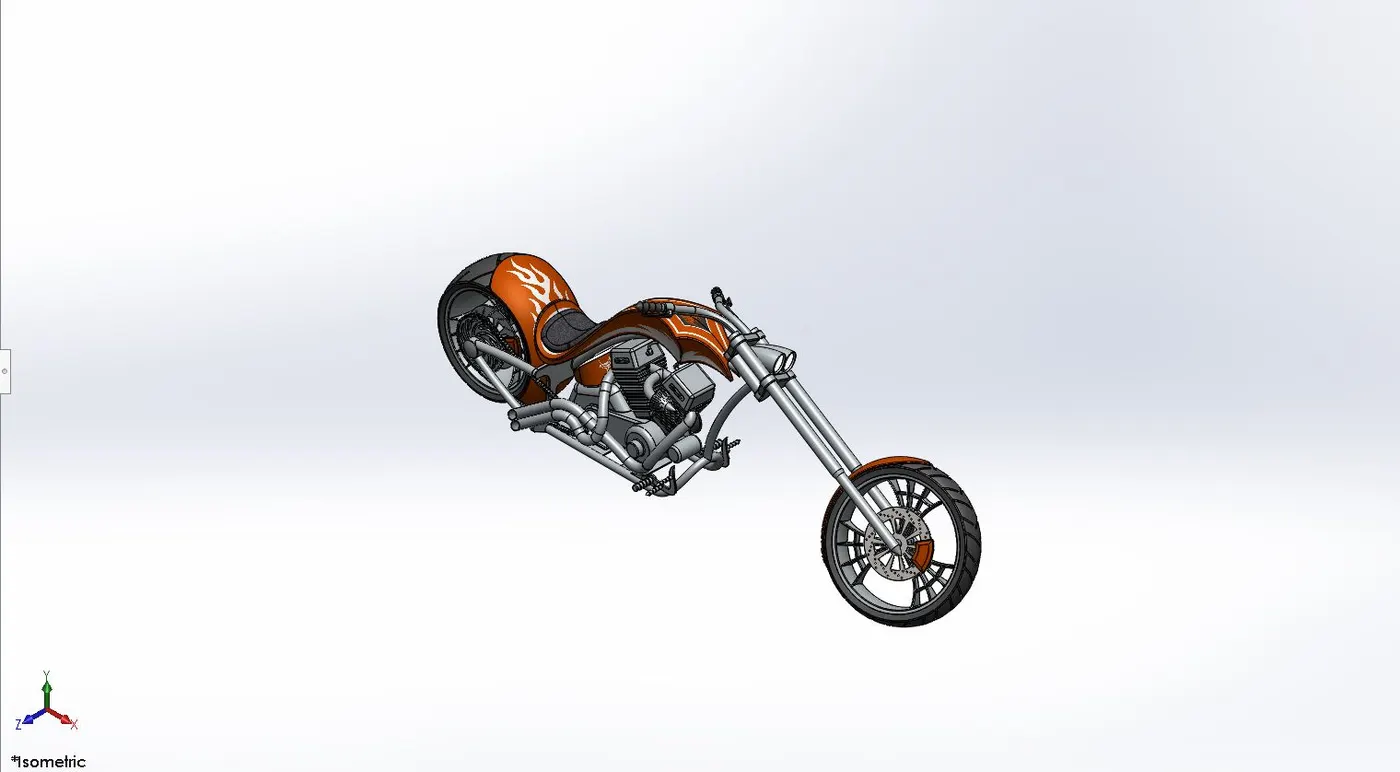
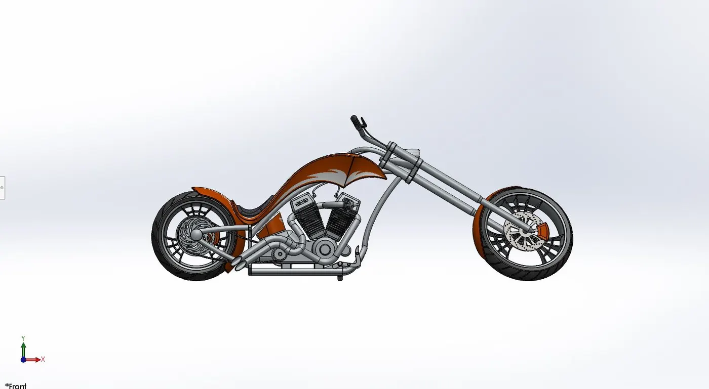
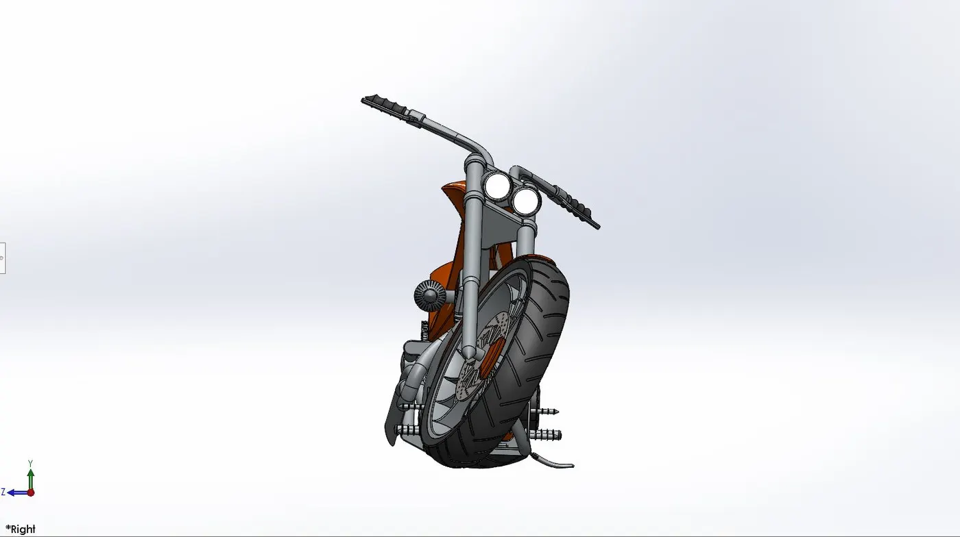
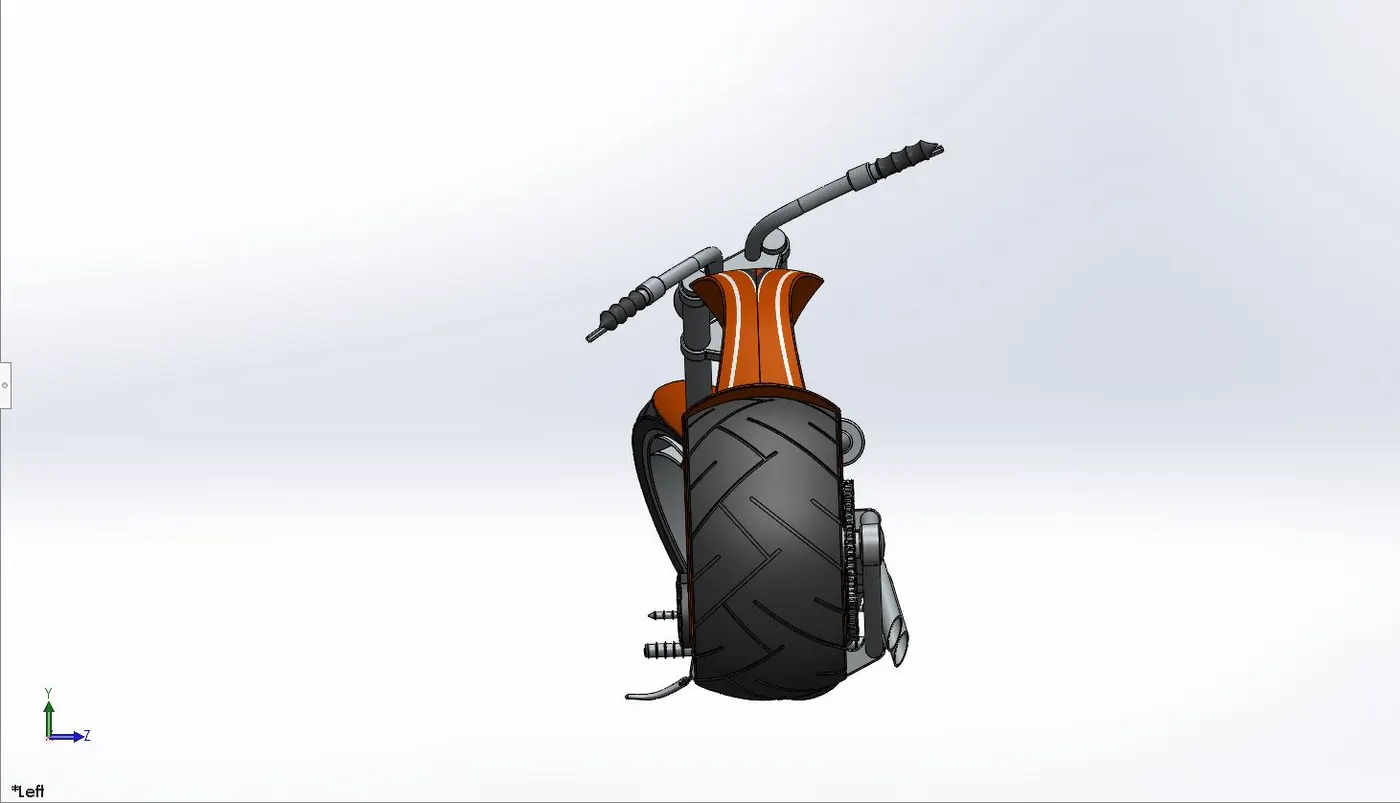
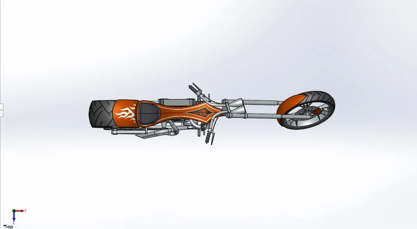
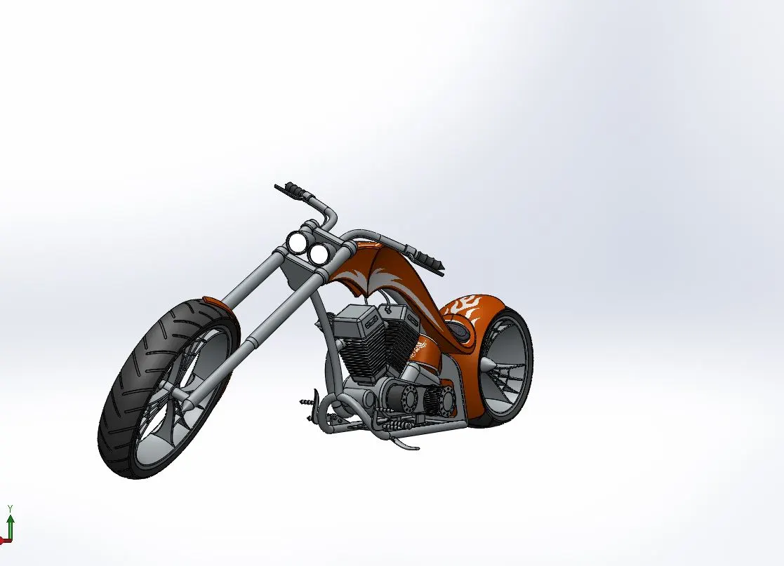
We used Solidworks assembly feature to assemble American chopper. Mates are applied to hold parts together.
Isometric view
Front view
Right side view
Left side view
Top view
Camera view
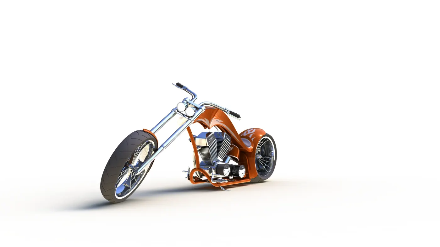
7.Rendering images –
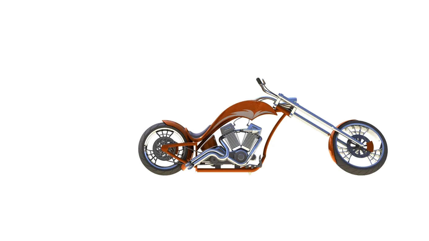
Kitchen white environment
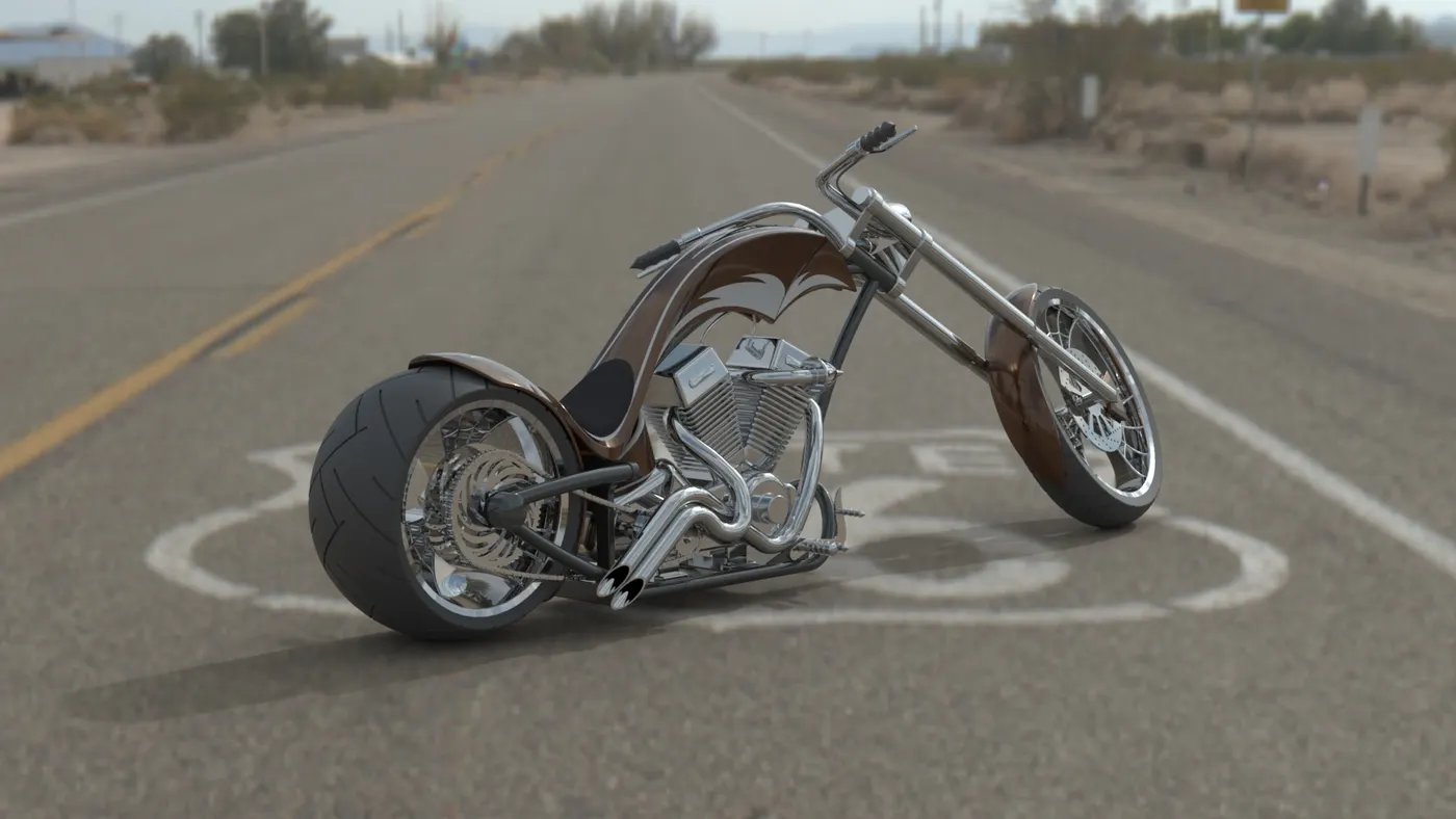
At Route 66
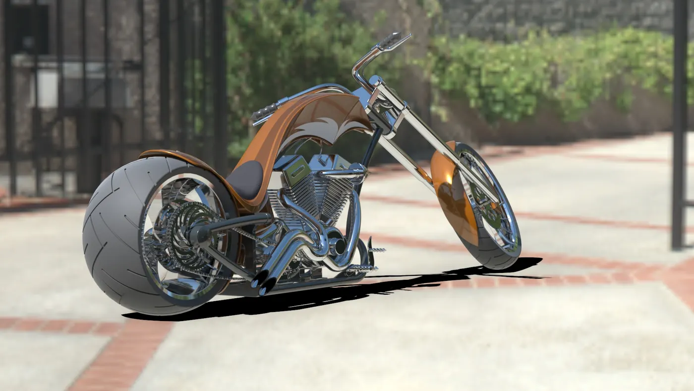
At Driveway
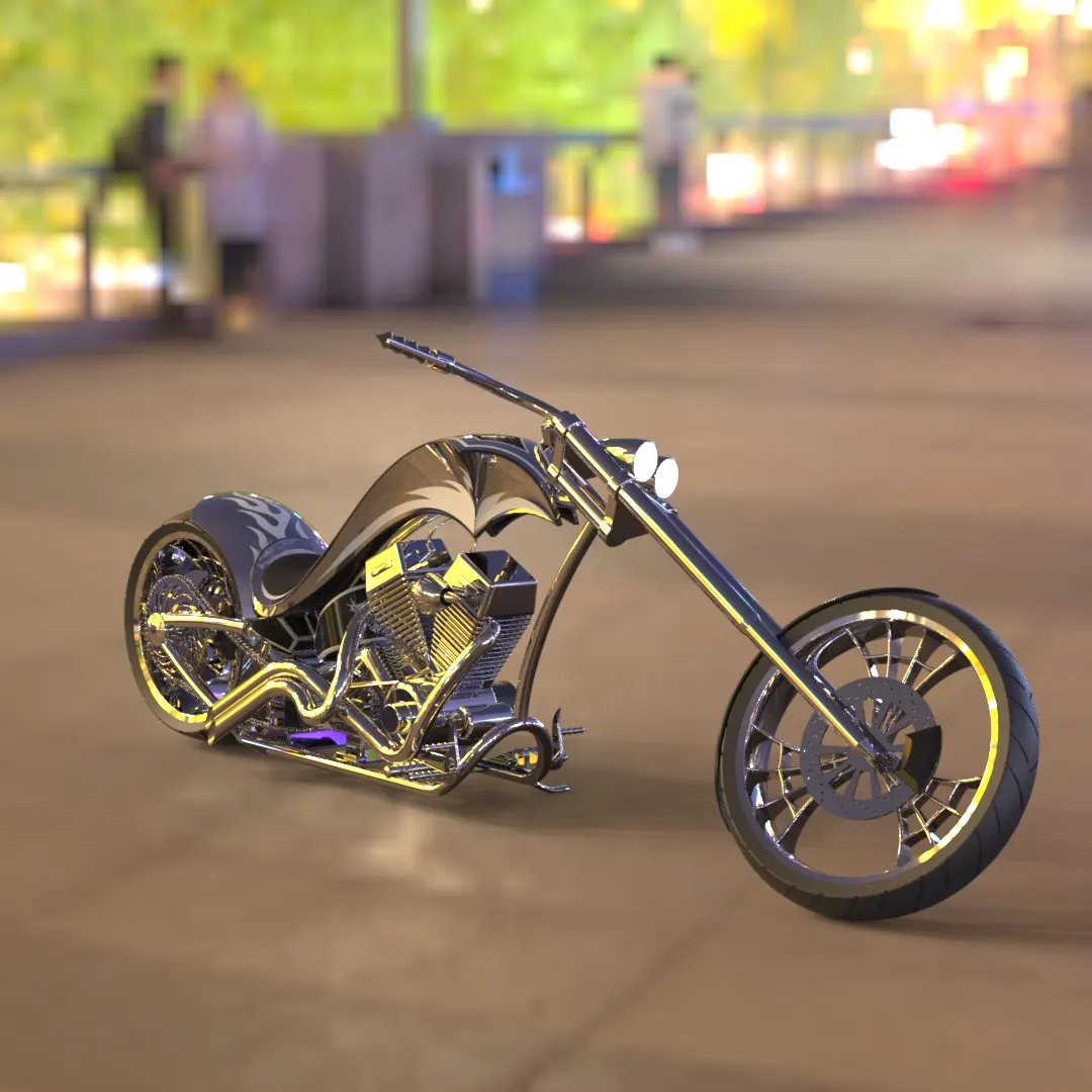
At Shangai Bund
At Walkway
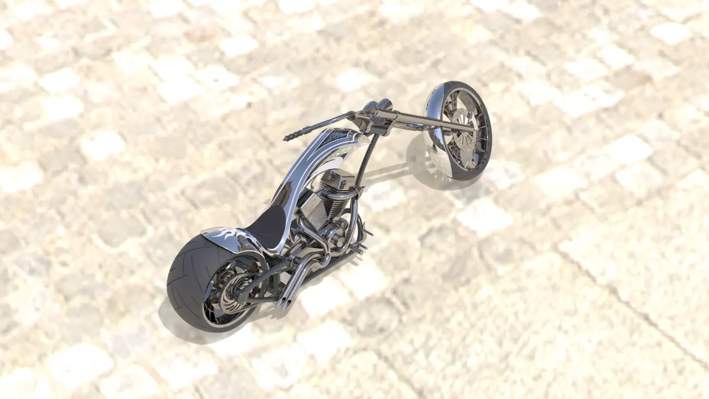
At Potsdamer Platz
8.Conclusion –
American chopper is assembled after modelling each component separately. Some of the parts were easy to model like oil tank, transmission belt etc. and other were complex like engine, gas tank etc, but features of Solidworks made things easy to model. We used sketch tools and features to model parts and some features of surface modelling also.After assembly we used photoview360 and Solidworks visualization to render realistic images of chopper.
The following link contains render projects and assembled model -
https://drive.google.com/file/d/13CuLW46UfaAA5LKhmZ4MB0A1VYGl-qke/view?usp=sharing