Week 12 Challenge
- Generate report for the steel building design from challenges 1 – 6 along with the loading summary
Answer:
Report Generation for a STEEL BUILDING DESIGN:
To Generate a Report first Analyse the Structure
Go to Analyse > Run Static Analysis
After Analysis is Completed.
Now Go to the Report in Ribbon
Report > Model report
The below Dialog box is shown;
Here it is selected for the required Data in the Report;
The parameters that can to included in the Report are:
Structure
Analysis
Concrete
Steel
timber
Cold formed
Cold Rolled
General Material
Member end forces
Bracing Forces
Foundation Reactions
picture
View
Analysis Diagram
Material Listing
Revision History
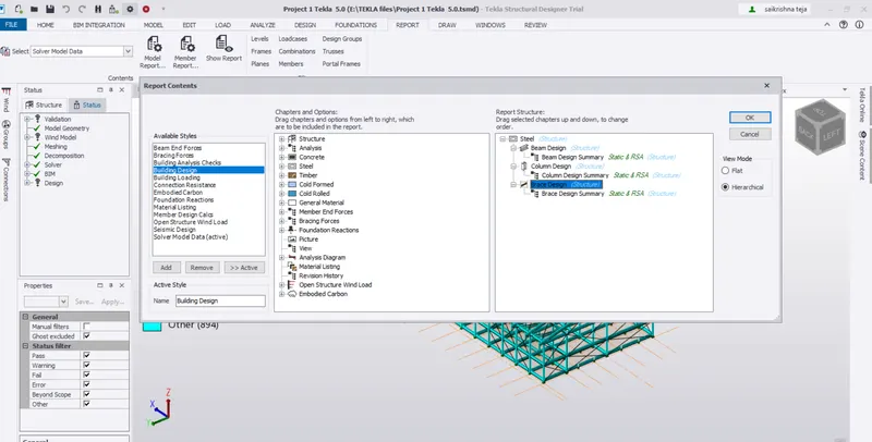
Data included can be
Building design
Buiding Analysis
Building Loading etc..
After selecting the Required Data;It is observed that the following Report is Generated.
The report shows the Required parameters that have been selected.
With the Help of this data it is easy to check and represent the Required Information.
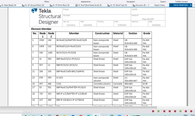
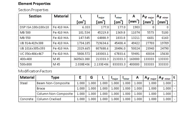
It is observed for a Steel Building the Elements used and their properties are Generated in the Report.
The Below sheet also include the Modification factors.
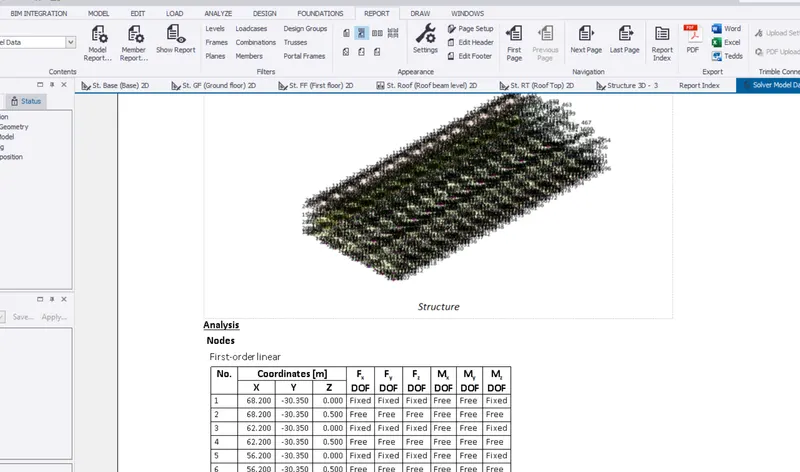
Similary in the STEEL BUILDING DESIGN it is easy to generate the Analysis also.
Analysis of the Steel Structure include
Nodes
Node support Details
Element Members
Element Properties
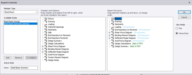
The Parameters which can formed in a sequemce to Generate a Report are:
Picture
Drawing
Restraints
Loading
End Reactions unfactored
Shear Force Diagram
Bending moment diagram
Deflected shape diagram
Axial force Diagam
Design calculations
Design summary
2.Generate report for RC structure along with the loading summary
Answer:
Reinforced Concrete Structure:
To Generate a Report first Analyse the Structure
Go to Analyse > Run Static Analysis
After Analysis is Completed.
Now Go to the Report in Ribbon
Report > Model report
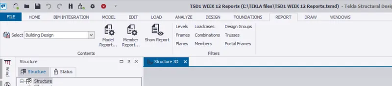
The below Dialog box is shown;
Here it is selected for the required Data in the Report;
The parameters that can to included in the Report are:
Structure
Analysis
Concrete
Steel
timber
Cold formed
Cold Rolled
General Material
Member end forces
Bracing Forces
Foundation Reactions
picture
View
Analysis Diagram
Material Listing
Revision History
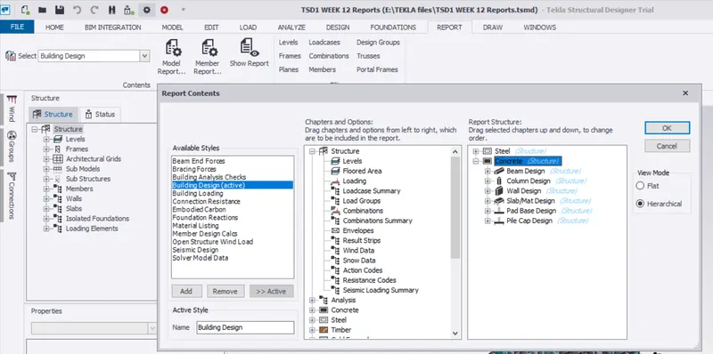
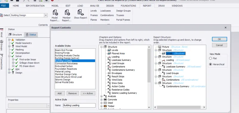
Data included can be
Building design
Buiding Analysis
Building Loading etc..
After selecting the Required Data;It is observed that the following Report is Generated.
The report shows the Required parameters that have been selected.
With the Help of this data it is easy to check and represent the Required Information.

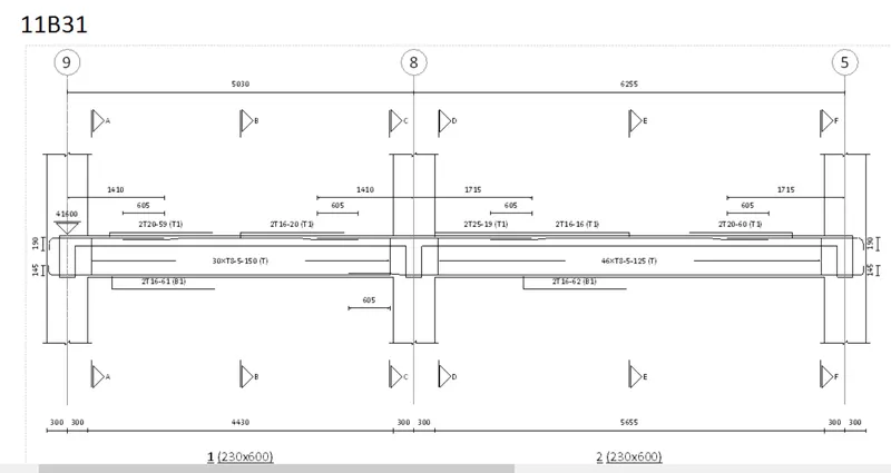
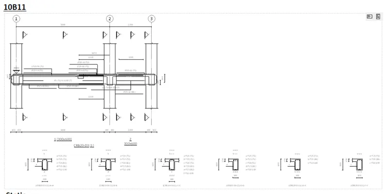
The Beam Diagram is shown in the Report with Reinforcement Details
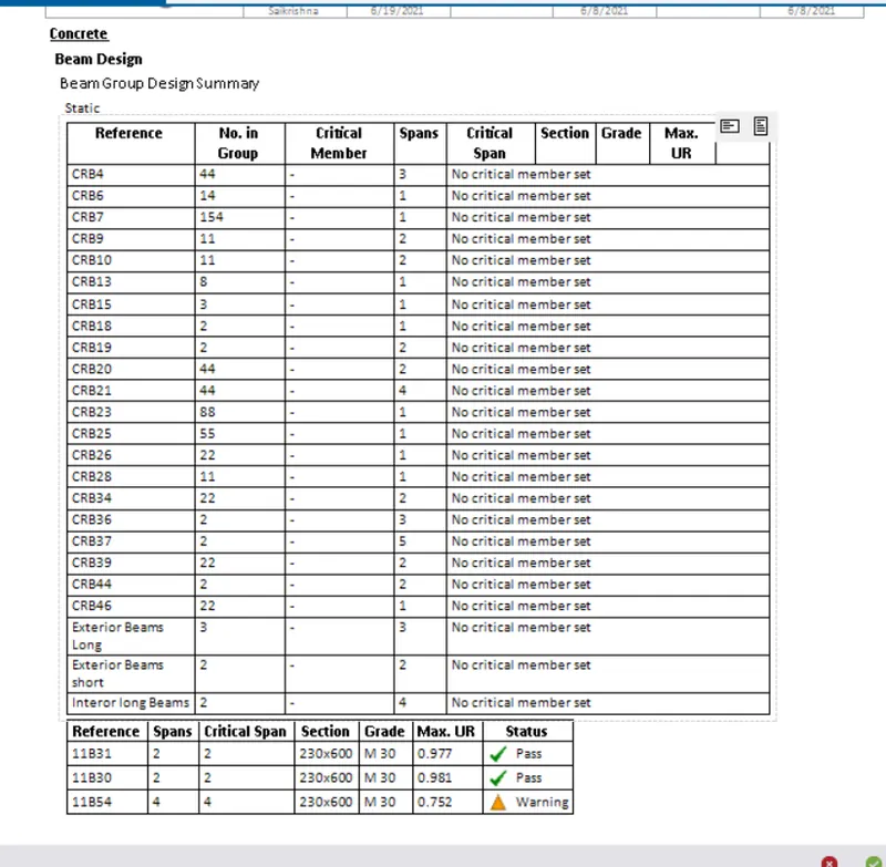
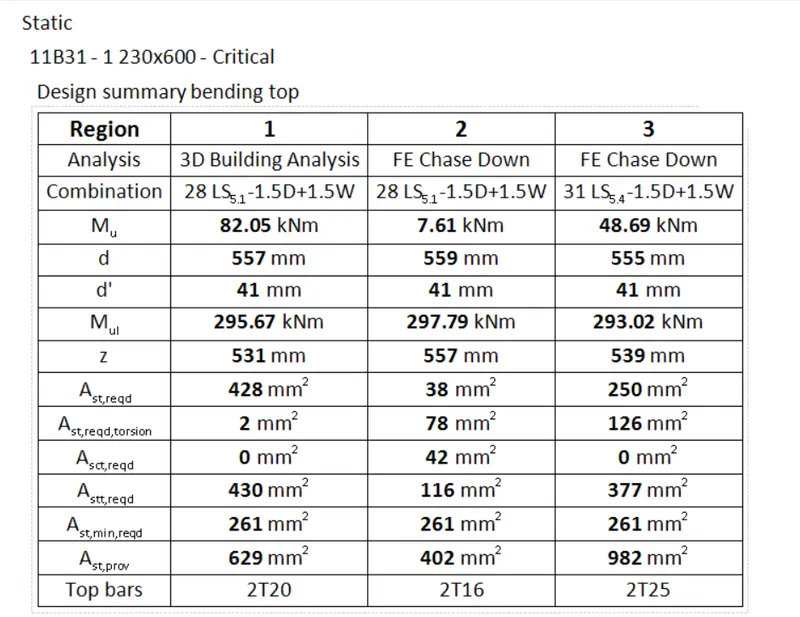
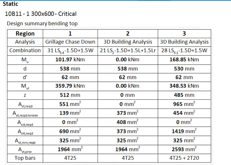
Design of Beams in the Report as shown below
The View of Bending at the Top for the Design Summary
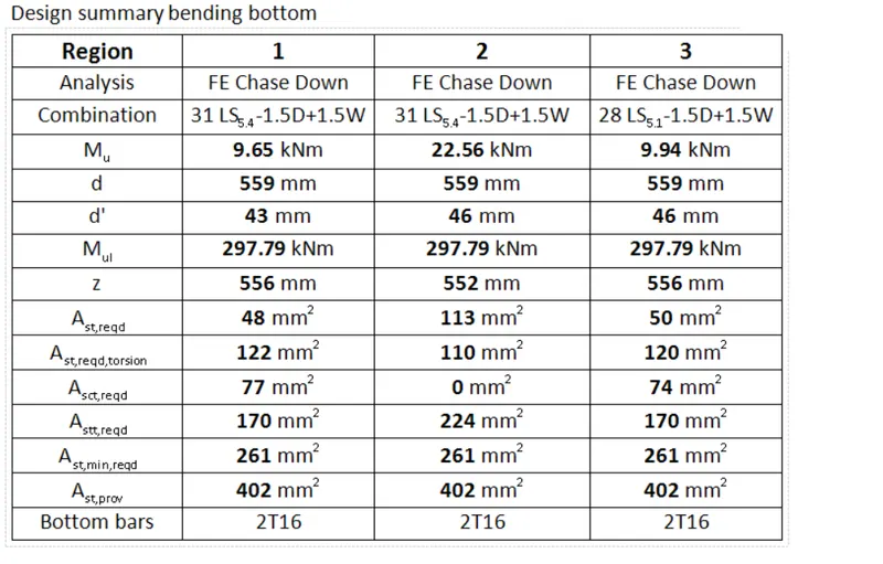
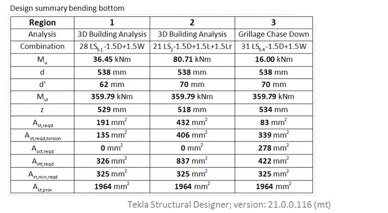
The View of Bending at the Bottom for the Design Summary
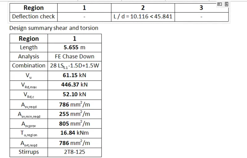
Deflection check for the Design and Shear and Torsion
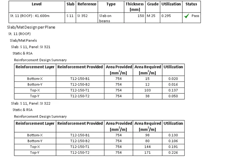
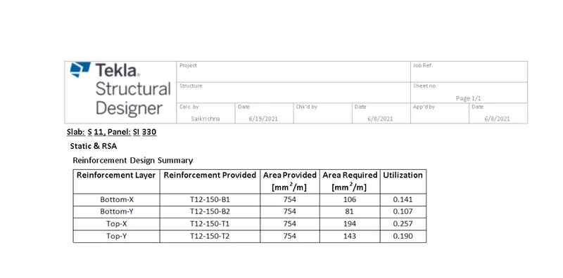
Slab and Mat Design Summary
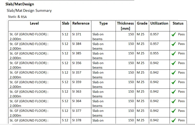
Based on the Levels Reinforecemnt are Generatedfor each slab Panel.
For Individual Members
Member Design:
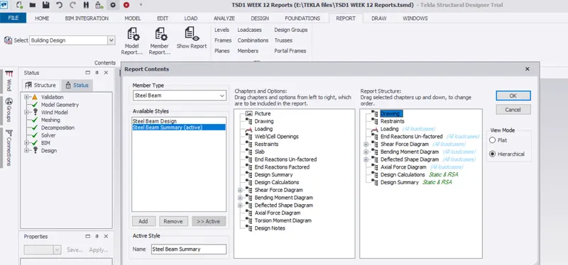
To do Member design Go to Report > Member Report
Design of Individual column:
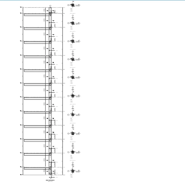
The Design of the Column member can be made for
Shear Force
Bending moment
Axial loading
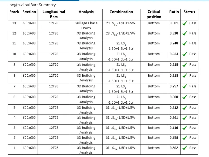
Longitudinal Bars for a Column Summary for Individual member in all Levels;
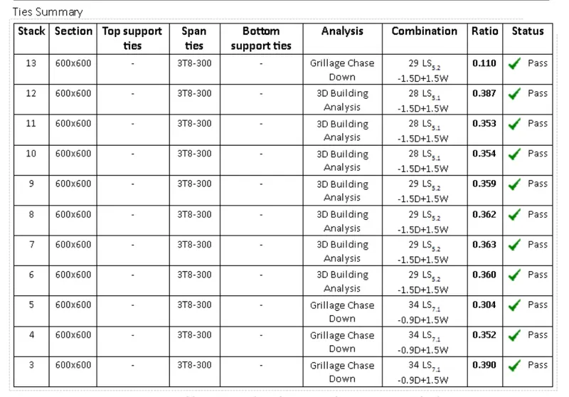
Ties Summary for a Column Summary for Individual member in all Levels;
Beam Summary for Individual member:
Static Analysis design for Beams:
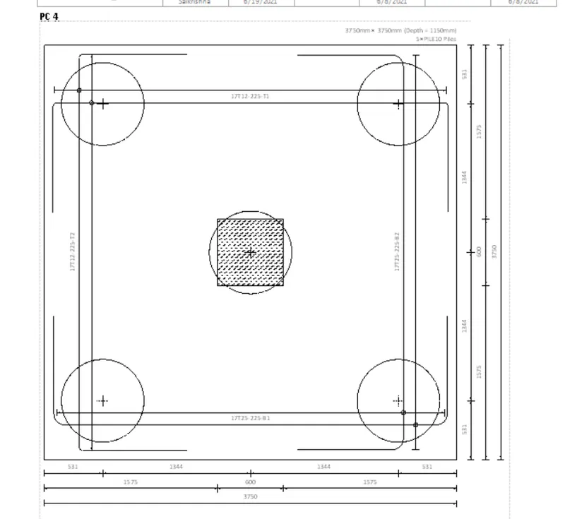
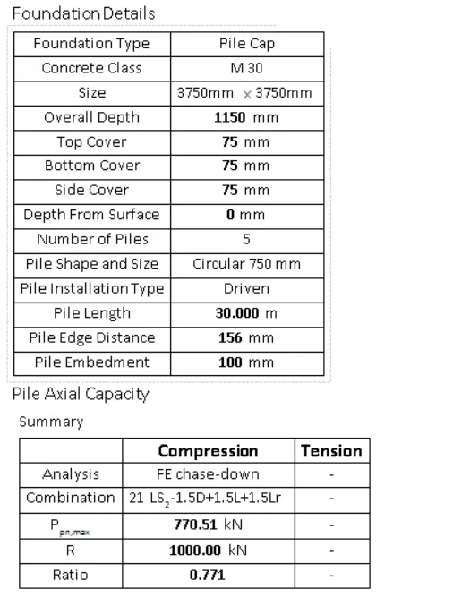
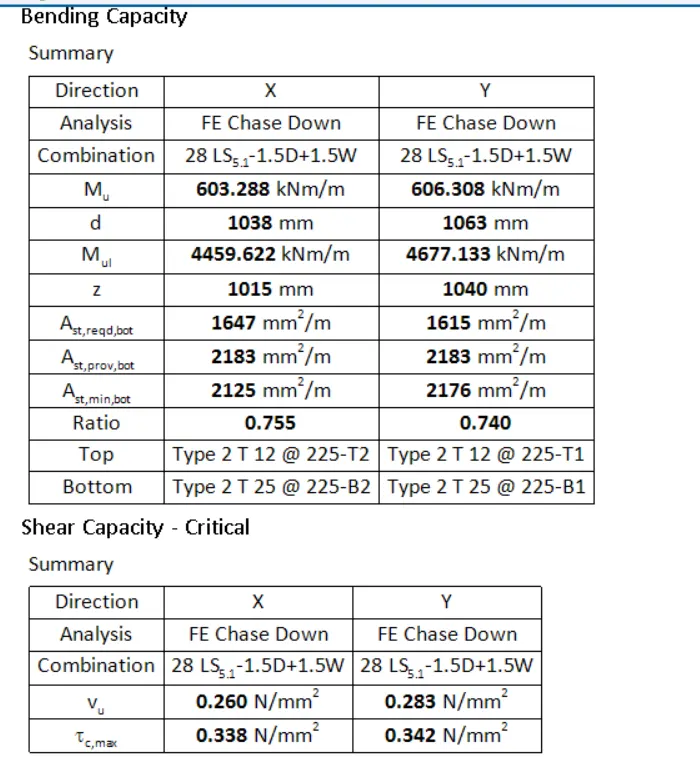
Pile Cap Design:
Individual design Pile Member
Drawing of the Pile Member
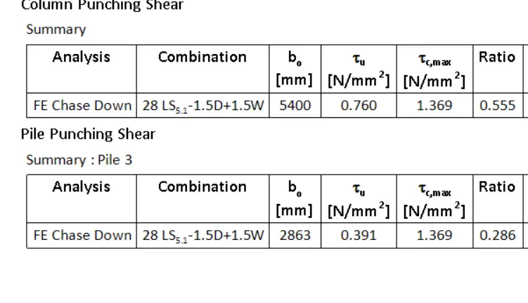
Result:
In the above report for RC Building it is observed for
1.Report of the whole structure
2.Individual Column design
3.Individual Beam Design
4.Individual pile Design
3.Update the layers settings in the model and generate plan drawings and details from the model
Answer:
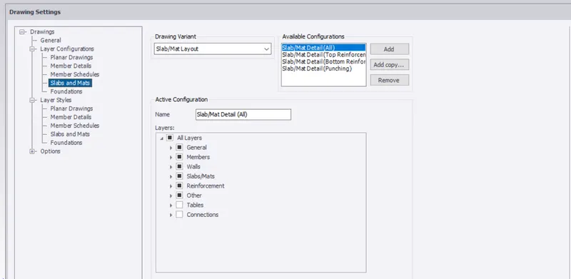
To Update the Layer settings
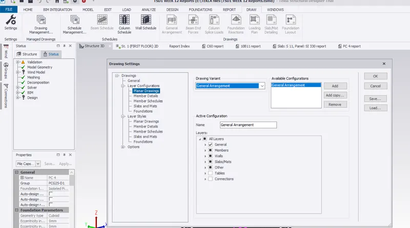
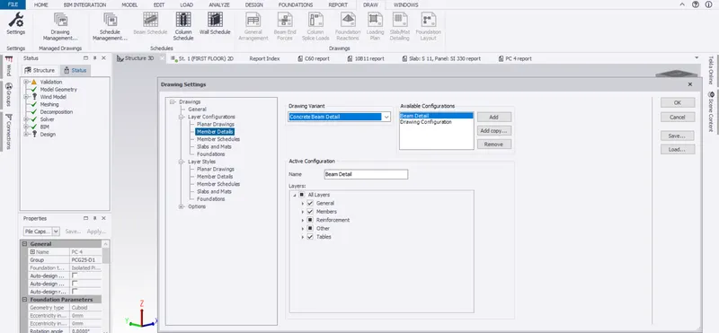
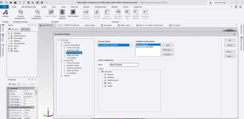
Go to Draw in the Ribbon > drawing management
there it is observed for the following Report Drawings
1.Planar Drawings for general Arrangements
2.Member Details for Concrete Beam
3.Member Schedule for Beam
4.Schedule for Mat/slab
5.Foundation Drawings
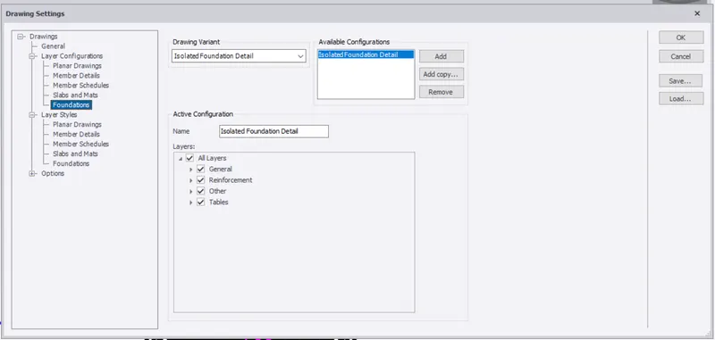
After knowing all the options ; Now prepare the Drawings and schedules for the Individual members
1.Column
2.Slab
3.Beam
4.Pile Foundation
5.Shear wall
1.Columns
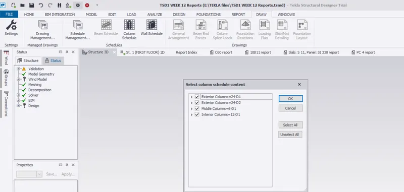
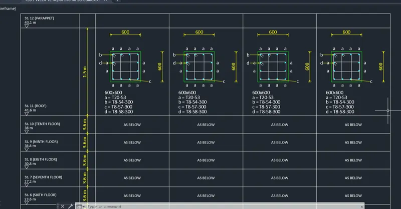
Columns Schedule and drawing Extracted in Auto cad Drawing
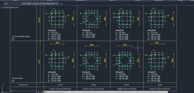
Columns Schedule and drawing Extracted in Auto cad Drawing
2.Slab or Mat Schedule and drawing
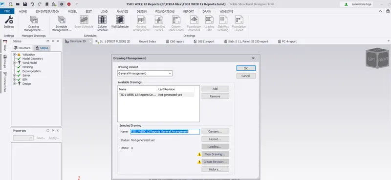
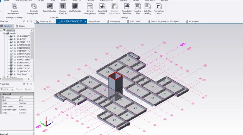
Go to Plan view for Slab Drawing Extraction
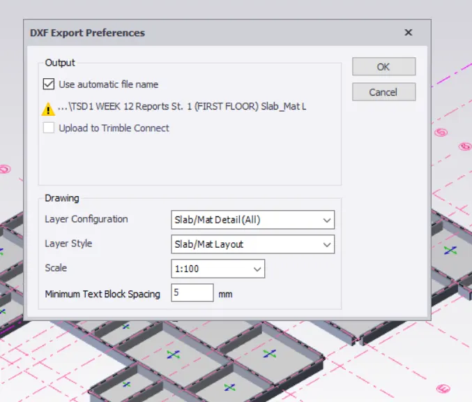
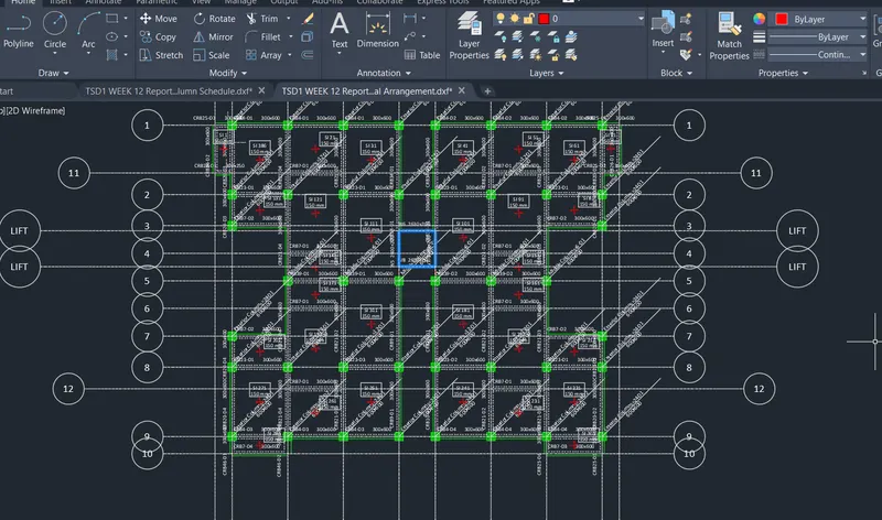
Drawing is extraced in the DXF file for Slab
Slab Schedule and drawing Extracted in Auto cad Drawing
3.Beam
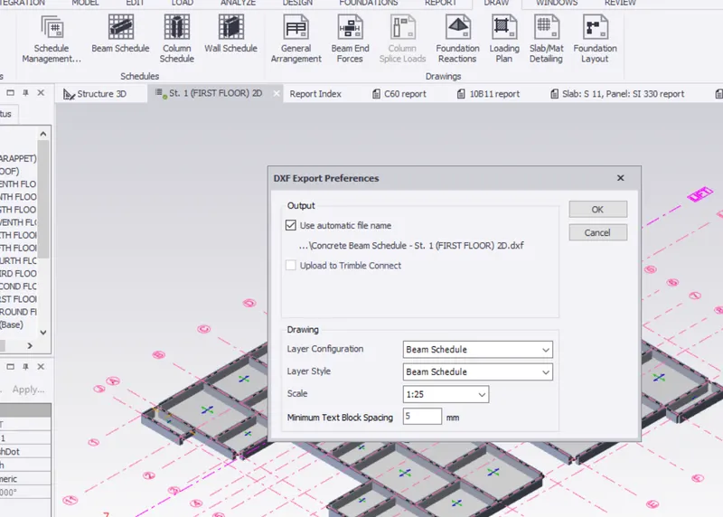
Drawing is extraced in the DXF file for Beam
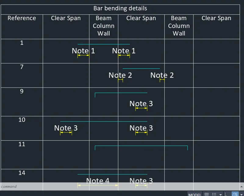
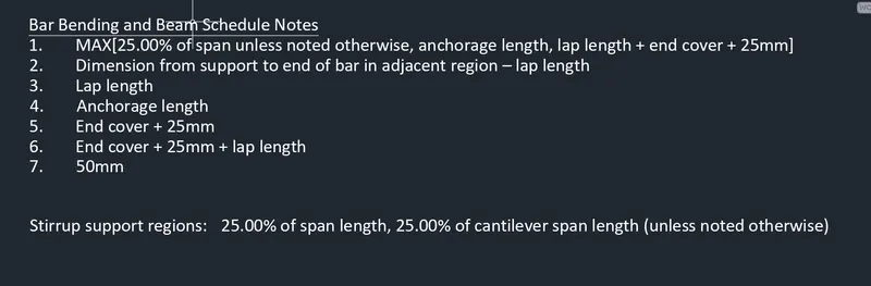
Bar Bending Schedule for Beam
Bar Bending Schedule and Notes for Beam
4.Foundation
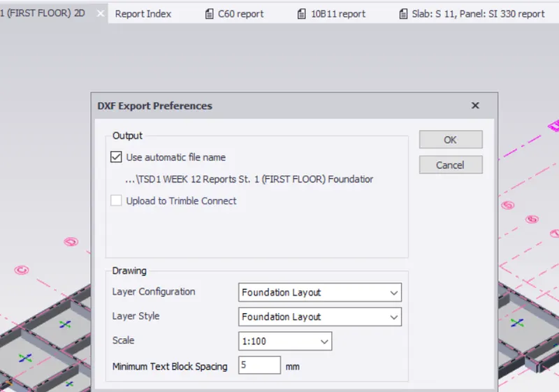
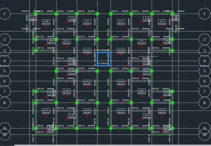
Go to Plan view for Foundation Drawing Extraction
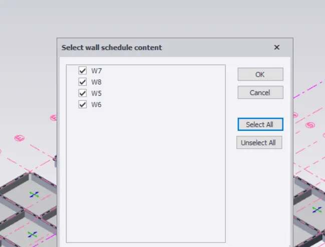
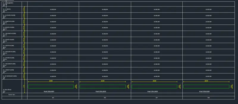
5.Shear wall Design Schedule