Introduction to REVIT concepts
Question1:
Aim & Introduction :
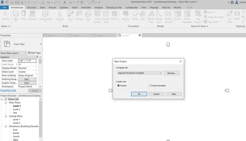
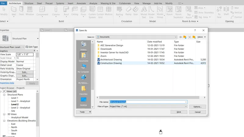
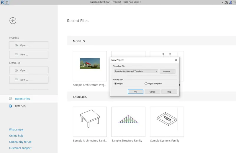
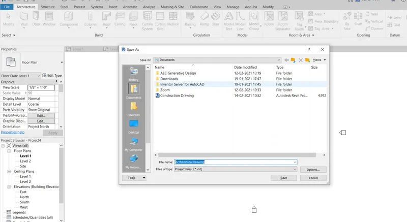
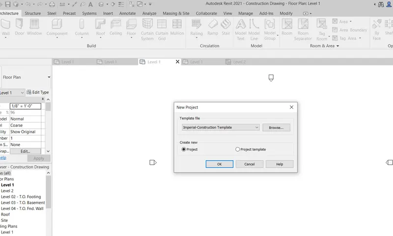
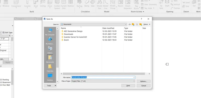
To create a new project (Structural / Architectural / Construction template ) from the file menu, and name the project appropriately
Procedure:
Go to File menu
Click on New
Slelect the Template
click on OK
Go to Save option
Save with the name
Result:
Question2:
Aim and Introduction:
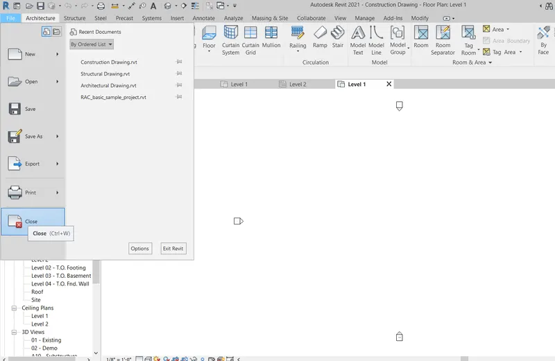
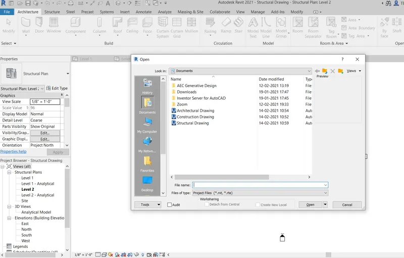
Save the new project file. Close and open using icons from file toolbar
Procedure:
Go to File menu and save the New project
Close Revit and open with the Name given
Result:
Question3:
Aim and Introduction:
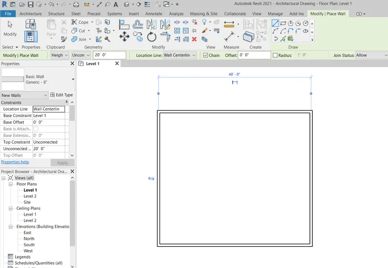
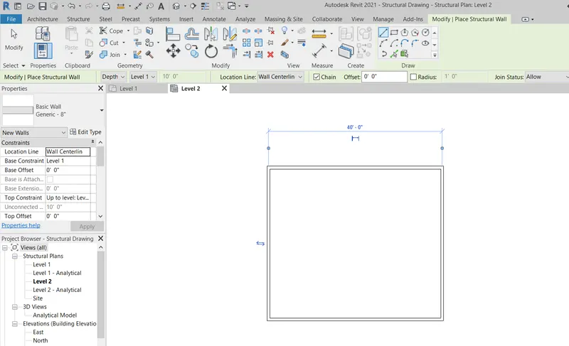
To draw a wall from the architecture/ structure toolbar and to Create a rectangular layout of walls of about 40’-0” X 35’-0”
Procedure:
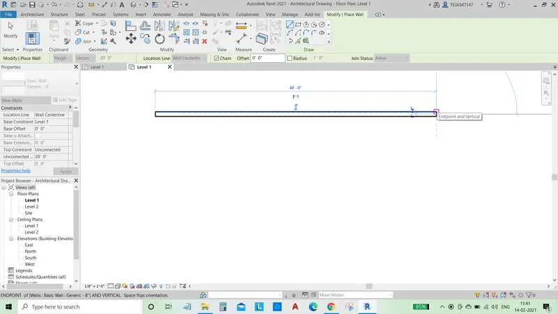
Click on Architecture Toolbar
Click on Wall (It is a non loadbearing wall)
Draw the wall 40'
Continue Drawing 35'
and make the rectangle Layout.
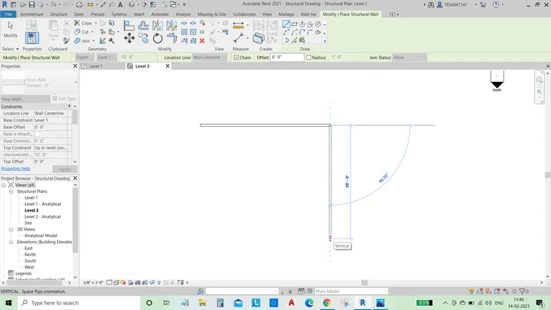
Simillarly in the Structural also.
Click on the Structure
Click in Wall (It is a Loadbearing wall)
Draw the wall 40'
Continue Drawing 35'
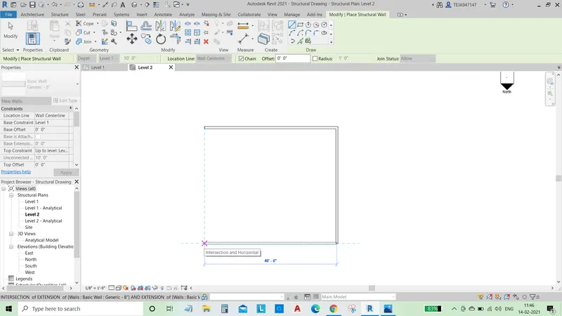
and make the rectangle Layout.
Result:
Question4:
Aim and Introduction:
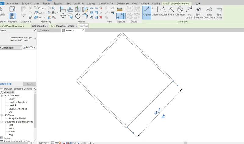
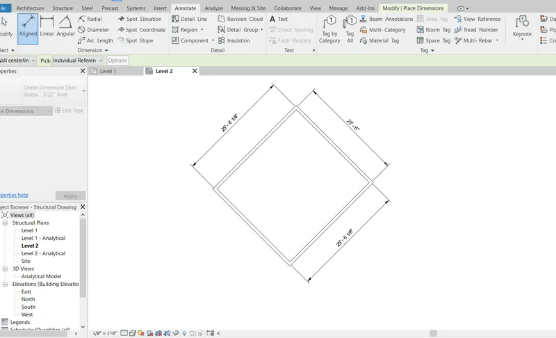
From the Annotate toolbar use the aligned option to add dimensions to the layout
Procedure:
Draw a rectangle wall of any size (Wall may be of architectural or structural)
Go to Annotate>Aligned
Draw the Dimension of the wall by selection
Result:
Question5:
Aim and Introduction:
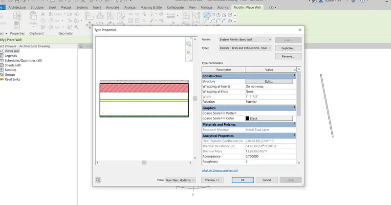
To Use the properties browser to switch to different wall types
Procedure:
Click on the wall in the Architecture
Go to Properties browser
The different types of wall available are
- Basic wall
- Curtain wall
- Stacked wall
Other properties are
Horizontal Grid
Structural
Dimensions
Identify Data
Result:
Question6:
Aim and Introduction:
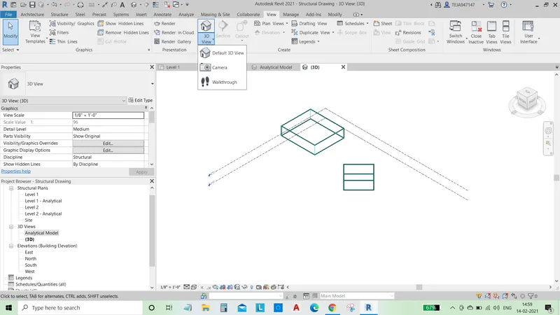
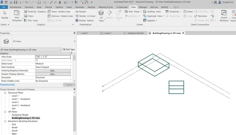
To Create a 3D view from the view toolbar and save the view with the appropriate name
Procedure:
Go to Project Browser Structural Drawing window which is in the left side of the REVIT workspace
Go to 3D views
Go to the Analytical Drawing or 3D
Now Remane it as "Building Drawing in 3D View"
Save the Window
Result:
Question7:
Aim and Introduction:
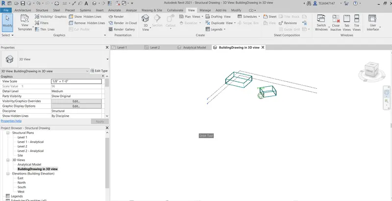
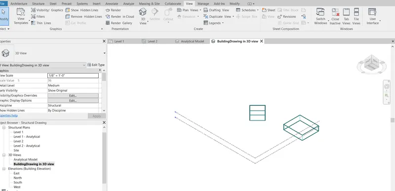
To Navigate through the 3D model using the view cube. Orbit/pan through the model layout created
Procedure:
Click on the Navigation Toolbar on the Right side of the workspace
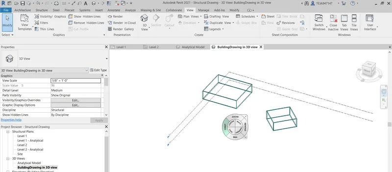
It shows the Navigation wheel which Contains Orbit,Pan,Rewind,Zoom
Press and hold on the Orbit and Navigate the workspace as per requirement
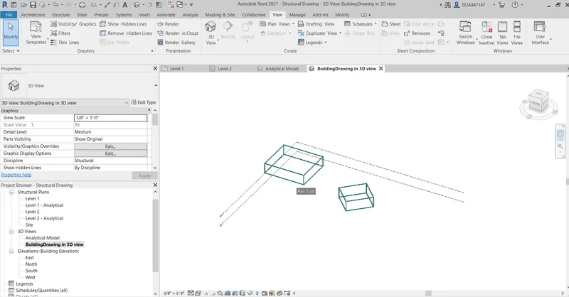
simillary Press and hold the Pan to Navigate in the workspce
Now using View Cube adjust the views as per the necessity
Views available are Top,Bottom,Right,Left,Front,Back
The corners of the cube gives the views like Southeast Isometric,Southwest Isometric,Northeast Isomertic and Northwest Isometric.
Result:
Question8:
Aim and Introduction:
To Use the visibility settings option below to switch model to shaded, realistic, hidden lines options
Procedure:
Click on the visual style (which is present at the bottom toolbar)
It consists of Graphic Display options Dialogbox
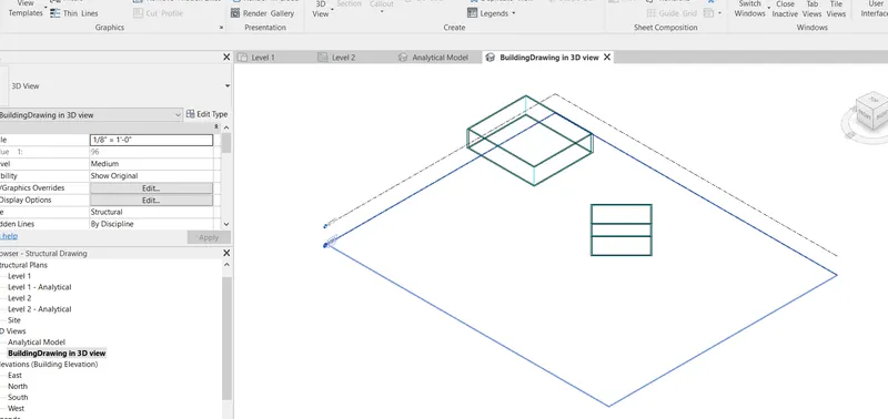
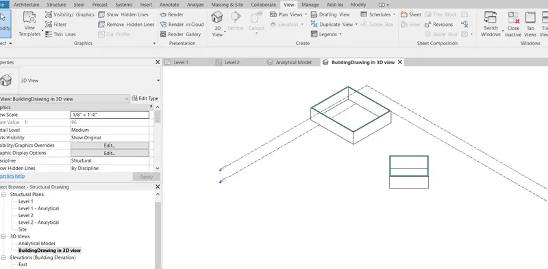
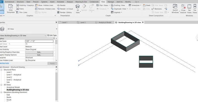
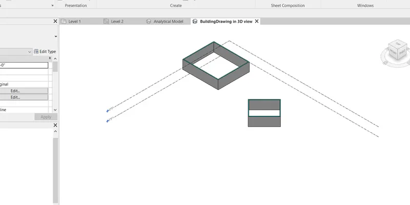
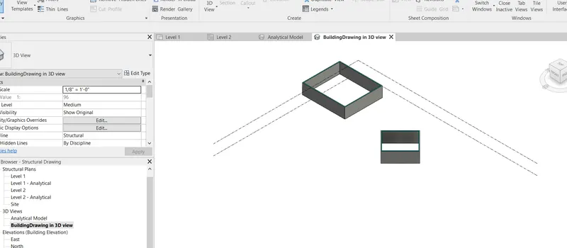
It shows differnt visibility settings option like wireframe,shaded, realistic, hidden lines,Consistent.
Result:
WireFrame
Hidden
Shaded
Consistent colors
Realistic
Question9:
Aim and Introduction:
To Turn the sun path on and off to view shadings in the layout created
Procedure:
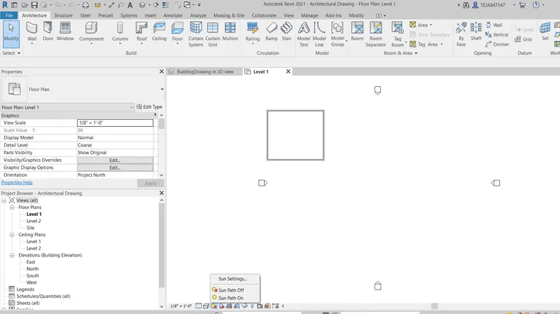
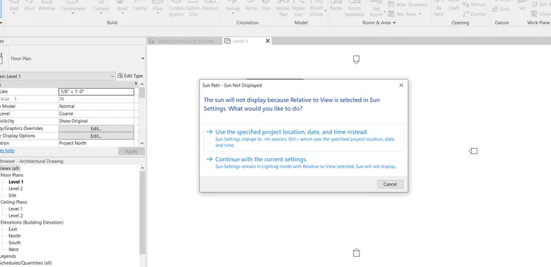
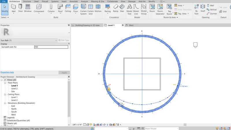
Click on the Sun Path(which is present at the bottom toolbar)
The size of the Sunpath can be changed with respective to the model size
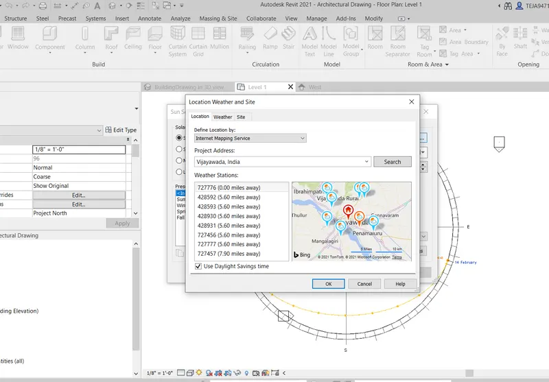
Also the Date and Time settings can be checked and adjusted accordingly to get the Sun path
It is also helpful in getting the postioning of the sun according to the location given
Result:
Question10:
Aim and Introduction:
To Use the Manage toolbar to enter project settings, project name, and project issue date.
Procedure:
Go to Manage Toolbar in the RIBBON
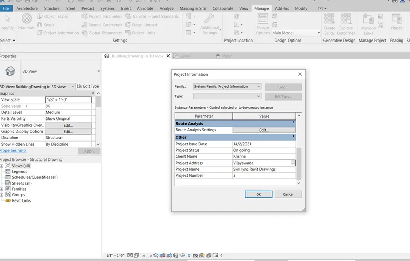
Go to Project Information
Now a Dialog box will be opened
Enter the Project settings that are necessary
Example:
Project Issue Date:14/2/2021
Project Status:On going
Clinet Name:Krishna
Project Address:Vijayawada
Project Name Skill lync Revit Drawings
Project Number : 3
Result:
Question11:
To know the Analyze toolbar used in Revit and How it is beneficial for design and modeling.
Answer:
Analyze Toolbar is used in the following ways
For Generating a Analytical Model:
To create Boundary Conditions
To generate loads
To create Load cases
To create Load combinations
For using Analytical Model tools:
To adjust the analytical model structural member
To Reset the analytical model Alignment methods
To Verify the Structural elements like Beams,columns,walls,Slabs are joined to the supporting elements.
Energy optimization of the Building elements and amount of the materials optimization
To Prepare heating and cooling loads based on the existing building model.
To check the Duct systems.
Question12:
What are the links that Revit supports to be linked to the model?
Answer:
The Links are available in Insert Toolbar
Link Revit : To Link another REVIT drawing in the existing drawing for getting the support elements or dimensions..
Link IFC : Linking IFC file to current project to reference its information for additional design work
Link CAD : To Link the AUTOCAD Drawing in the existing REVIT Drawing for matching the 2D elements in the Drawing with the Supports and to attain structural configurations accurately meeting without changing the Plan.
link Topography : To get the elevations of the drawing meeting with the present AUTOCAD Drawings
Link PDF : To insert the link in a MODEL VIEW
Link Image : To inset an IMAGE into MODEL VIEW
Question13:
Why do you need the Collaborate tab in Revit? How it supports modeling and its efficiency
Answer:
Colloboration enables the Team members to Work in a model simultaneously.
It supports in Communication between the files or Drawings.
It helps to have the workshare among the Team members.
It saves a selected Backup version to the Current working model and rolls back changes made to workshared project.
It also specifies the Mapping of the drawings when copying the MEP fixtures from a linked model.
It makes the work management efficient among the MEP team and make the work easier and faster.