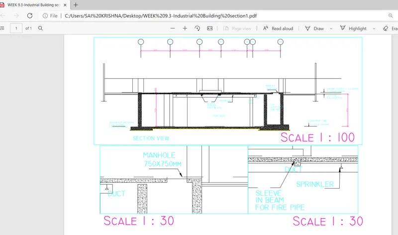
Creation of Multiple viewports, Scaling the drawing and setting in Template in AutoCad
Drawing1:
Aim:
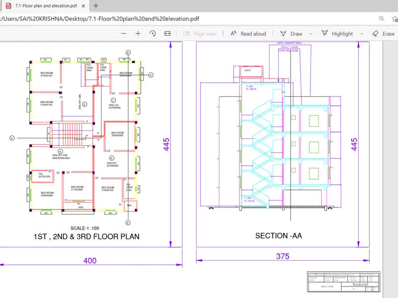
To Create a layout of the Floor Plan and Section A of the Building and to take a plot.
Introduction:
The given drawings are coverted into PDF and printed for making the Drawing sheets Using the template TutorialmArch.dwt
Procedure:
The Drawings after created in Autocad are converted into PDF using the following procedure:
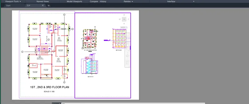
- A layout is created for the given drawing as per requirement.
- The layout is renamed as per the Drawing name or any other name Convenient.
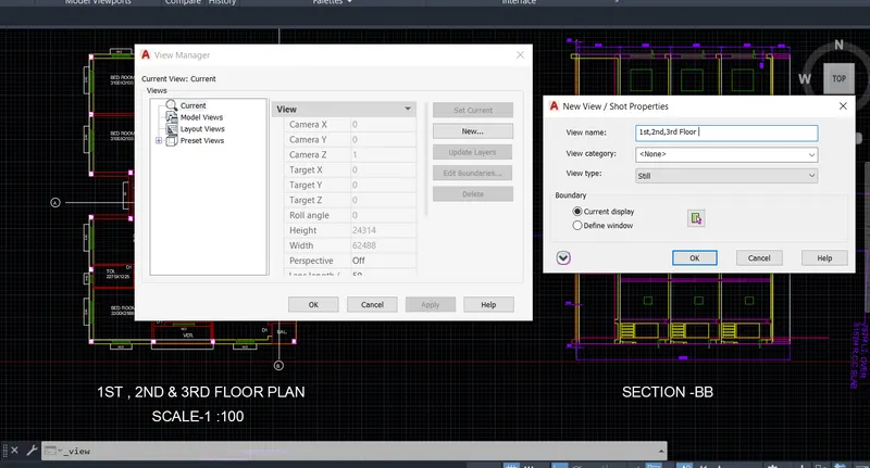
- New views are created using the VIEW MANAGER in the Drawing for easy viewing of the reqiured PLAN or ELEVATION or SECTION.
- Later the same Drawing is taken as the viewport for making views as per the requirement.
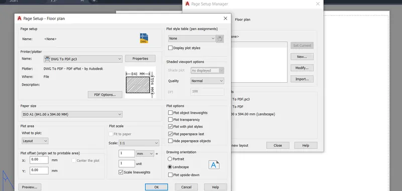
- Firstly the Paper of required dimension is taken.
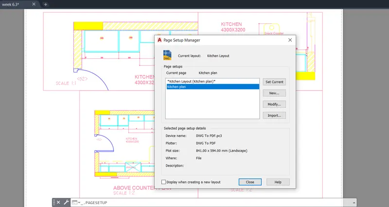
- It is obtained from PAGE SET UP MANAGER.
- Here it is used to Create New setup or Modify the Existing setup
- Later the paper view can be adjusted in Paperspace by Zooming in or Out.
- Command : PS or PSPACE
- The Plan or section or Elevation is taken in Modelspace and adjusted as per the scale.
- Command : MS or MSPACE
- Generally to represent different drawings in a single sheet,the sheet is made as tiles in the PAPERSPACE.
- Command : MV or
- UsING the MV command to create the viewport.
- The Drawing is adjusted in the Tiles of the Paperspace using the following command
- Command : PAN
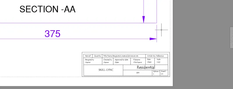
- Templates drawings can also be inserted while plotting.
- Some template drawings which are made as Blocks are also inserted.
For Plotting:
- After finishing all the adjustment in both Paper and Modelspace the Drawing is converted to pdf.
- For printing the Drawing the settings are checked and made ready to print.
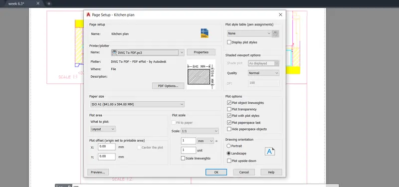
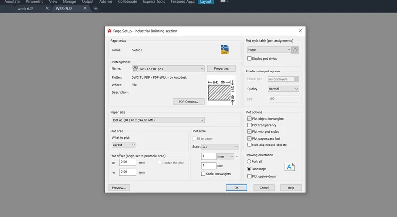
- Settings include in the PAGE SETUP are:
- Paper size, Plot Area, Plot style Table, Plot Options , Drawing Orientation ,Plot Scale etc..
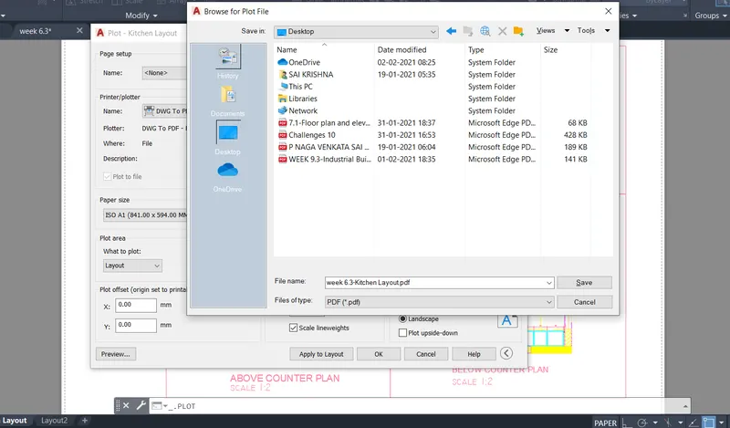
- The PDF Drawing is saved in the Folder and named conveniently.
- Finally the Drawing is Printed.
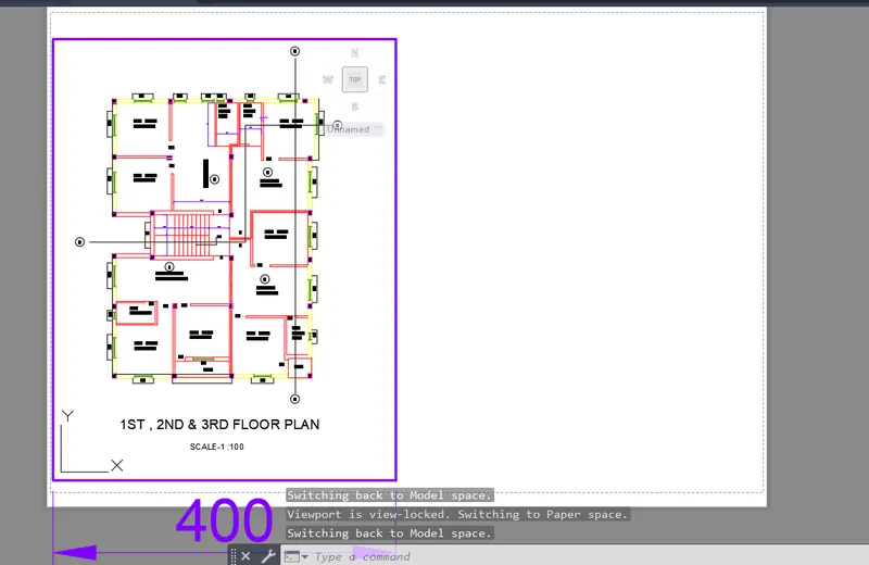
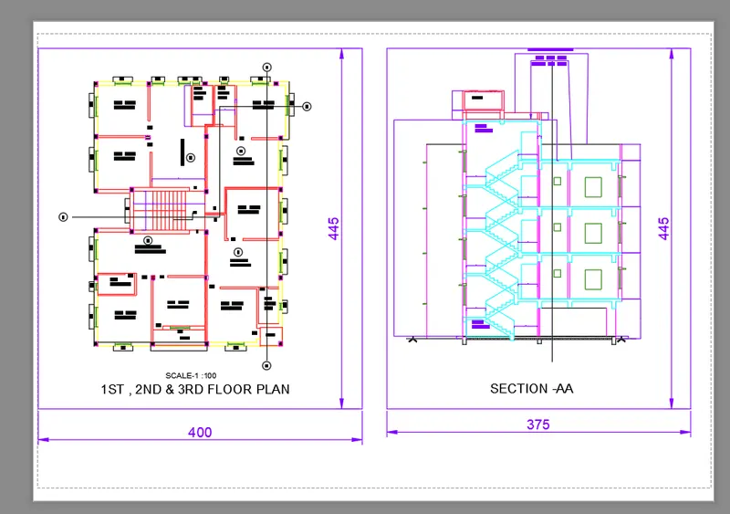
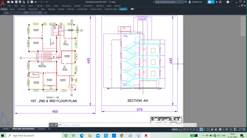
Result:
The PDFs are attached in the link below
Drawing2:
Aim:
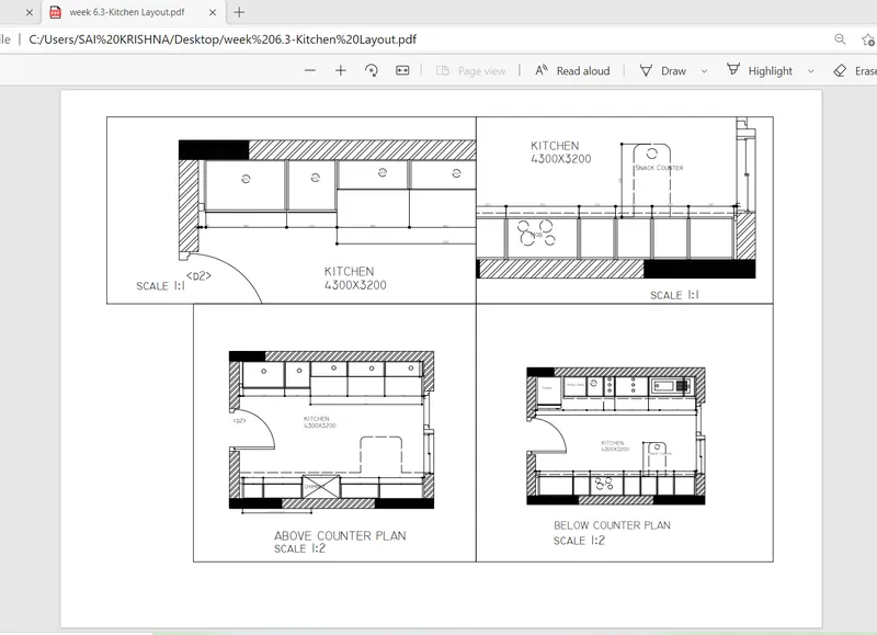
To Create a layout of the Kitchen plan (Both Above Counter plan and Below Counter plan) and to take a plot.
Introduction:
The given drawings are coverted into PDF and printed for making the Drawing sheets Using the template TutorialmArch.dwt
Procedure:
The Drawings after created in Autocad are converted into PDF using the following procedure:
- A layout is created for the given drawing as per requirement.
- The layout is renamed as per the Drawing name or any other name Convenient.
- New views are created using the VIEW MANAGER in the Drawing for easy viewing of the reqiured PLAN or ELEVATION or SECTION.
- Later the same Drawing is taken as the viewport for making views as per the requirement.
- Firstly the Paper of required dimension is taken.
- It is obtained from PAGE SET UP MANAGER.
- Here it is used to Create New setup or Modify the Existing setup
- Later the paper view can be adjusted in Paperspace by Zooming in or Out.
- Command : PS or PSPACE
- The Plan or section or Elevation is taken in Modelspace and adjusted as per the scale.
- Command : MS or MSPACE
- Generally to represent different drawings in a single sheet,the sheet is made as tiles in the PAPERSPACE.
- Command : MV or
- UsING the MV command to create the viewport.
- The Drawing is adjusted in the Tiles of the Paperspace using the following command
- Command : PAN
- Templates drawings can also be inserted while plotting.
- Some template drawings which are made as Blocks are also inserted.
For Plotting:
- After finishing all the adjustment in both Paper and Modelspace the Drawing is converted to pdf.
- For printing the Drawing the settings are checked and made ready to print.
- Settings include in the PAGE SETUP are:
- Paper size, Plot Area, Plot style Table, Plot Options , Drawing Orientation ,Plot Scale etc..
- The PDF Drawing is saved in the Folder and named conveniently.
- Finally the Drawing is Printed.
Result:
Drawing3:
Aim:
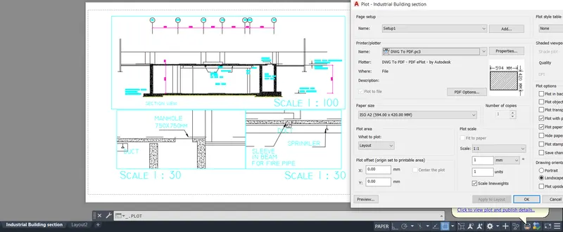
To Create a layout of the Industrial Building and the Section of the Building and to take a plot.
Introduction:
The given drawings are coverted into PDF and printed for making the Drawing sheets Using the template TutorialmArch.dwt
Procedure:
The Drawings after created in Autocad are converted into PDF using the following procedure:
- A layout is created for the given drawing as per requirement.
- The layout is renamed as per the Drawing name or any other name Convenient.
- New views are created using the VIEW MANAGER in the Drawing for easy viewing of the reqiured PLAN or ELEVATION or SECTION.
- Later the same Drawing is taken as the viewport for making views as per the requirement.
- Firstly the Paper of required dimension is taken.
- It is obtained from PAGE SET UP MANAGER.
- Here it is used to Create New setup or Modify the Existing setup
- Later the paper view can be adjusted in Paperspace by Zooming in or Out.
- Command : PS or PSPACE
- The Plan or section or Elevation is taken in Modelspace and adjusted as per the scale.
- Command : MS or MSPACE
- Generally to represent different drawings in a single sheet,the sheet is made as tiles in the PAPERSPACE.
- Command : MV or
- UsING the MV command to create the viewport.
- The Drawing is adjusted in the Tiles of the Paperspace using the following command
- Command : PAN
- Templates drawings can also be inserted while plotting.
- Some template drawings which are made as Blocks are also inserted.
For Plotting:
- After finishing all the adjustment in both Paper and Modelspace the Drawing is converted to pdf.
- For printing the Drawing the settings are checked and made ready to print.
- Settings include in the PAGE SETUP are:
- Paper size, Plot Area, Plot style Table, Plot Options , Drawing Orientation ,Plot Scale etc..
- The PDF Drawing is saved in the Folder and named conveniently.
- Finally the Drawing is Printed.
Result: