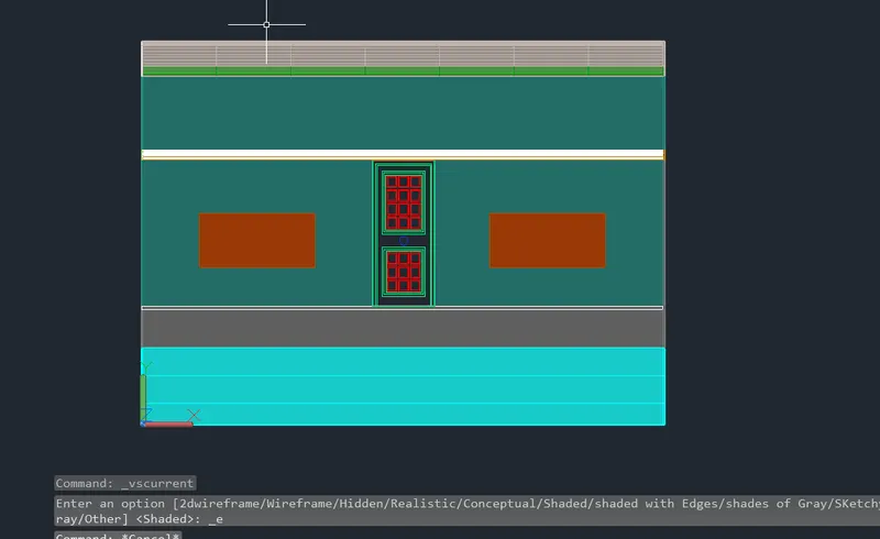
Creating 3D Isometric view of various structural elements in AutoCAD
Drawing1:
Aim:
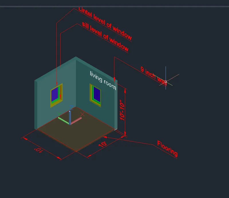
To Create a 3D Isometric View of the building with plan and elevation.
Introduction:
The Plan and elevation of the building are drawn in 3D view by creating different layers , views ,including different building elements to make it an aesthetic apperance.
Procedure:
The plan and elevations are drawn with the given dimensions in 2D
They are taken to 3D modelling for the necessary changes
In this 3D Modelling
the Plan is made as the reference for the Elevation for Creating Bondaries.
The Elevation is rotated and the view is changed to isometric for visualization.
Commands used are
3D ROTATE: To rotate the objects into Isometric view
NEWVIEW : To create views for the Plan and elevation for further progress.
Now Boundaries are created for the Elevation.
Next the Regions are generated.
Commands used are
BOUNDARY : To create Boundaries for the closed objects
REGION : To make the planar objects
The Objects are Extruded for 3D visualization.
The unnecseccary or additional objects are subtracted as per the Extrusion requirements of the Objects.
Commands used are
SOLIDEDIT>EXTRUDE
SOLIDEDIT>SUBTRACT
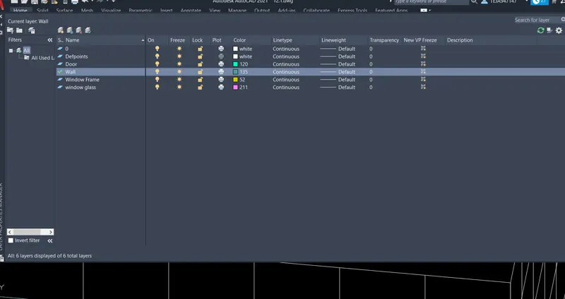
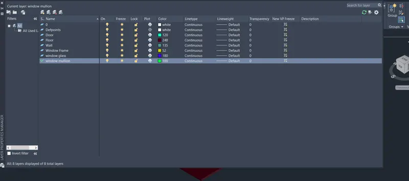
Layers are created for the different elements in the building like
Windows,Window Frame,Window Mullion,Walls,Dimensions.
For the ease of the Drawing construction the layers are very much helpful.
Commands used are
LAYERS: To create layers for different Elements
Doors or windows are created by drawing a rectangle in the respective coordinate view.
Later the rectangle is created as a region and Extruded to form a window or door.
The Coordinates are changed according to the position of the view that is required for operation in that Plane.
Coomands used are:
UCS>FACE>ACCEPTX or Y or Z or Zaxis are selected as per requirement.
The UCS command is activated for operation or for creating an element on the face of the Wall.
Later the Views with respect to coordinates are saved and named.
The walls are adjusted for making Doors and window units and they are inserted in the wall openings.
Then different colours for the elements of a Window are provided.
The window is extruded as per the given thickness.
The views are changed accordingly for different usage and ease of the construction of the Drawing.
The Views are named after their usage like V1,V2,V3...
All the elements are constructed using the above command sin different views respectively.
The Constructed elements can be adjusted using SOLIDEDIT commands
The Dimensions are mentioned as per the given drawing.
Command used are
DIMSTYLE
DIMLINEAR
To mention Dimensions in the respective coordinate of the element again the UCS command is used.
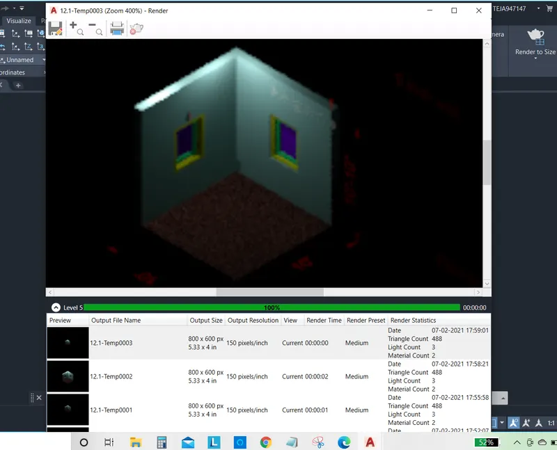
Later Rendering of the elements is done
Command used is
RENDER or RR
The material properties are given using commands like
MATERIALBROWSER
MATERIAL MAPPING
The Suitable Material is given accordingly for all the Building elements.
Generally for Flooring:Concrete
For windows:wood
For walls: Bricks
These are selected in the MATERIAL BROWSER dialog box and MAPPED to the respective element.
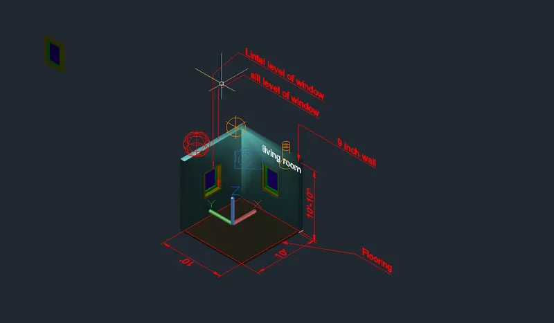
Lights are Created for illumination of the rooms.
The lights available are Ponit light,Spot light, Distint Light, Web light
Commands used are
VISUALISE>LIGHTS>POINT LIGHT
VISUALISE>LIGHTS>SPOT LIGHT
VISUALISE>LIGHTS>DISTINT LIGHT
VISUALISE>LIGHTS>WEB LIGHT
The properties of the light are changed in the properties command.
The changes made are like change in Name,Status ON/OFF,Illimination,Lamp intensity.
The made changes are rendered in the rendered view.
A camera is fixed to have the view of the Rendered object,
Command used is
VISUALISE>CAMERA
Camera is fixed in the room for viewing the changes that occur by changing the properties.
Finally the required Drawing is established.
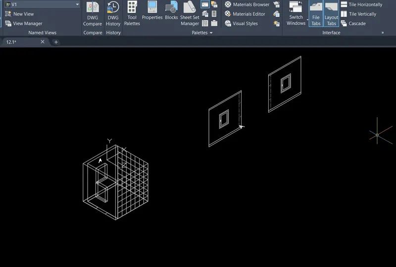
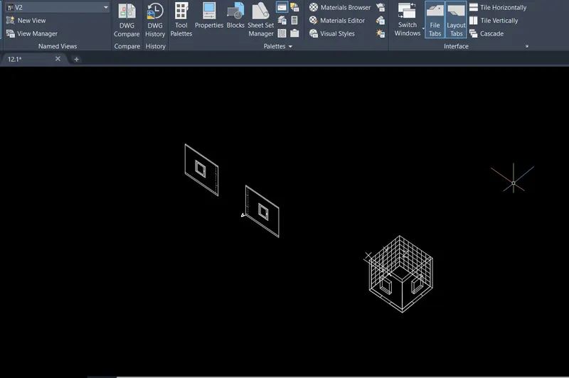
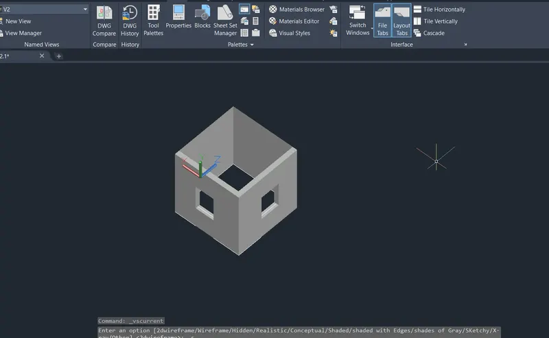
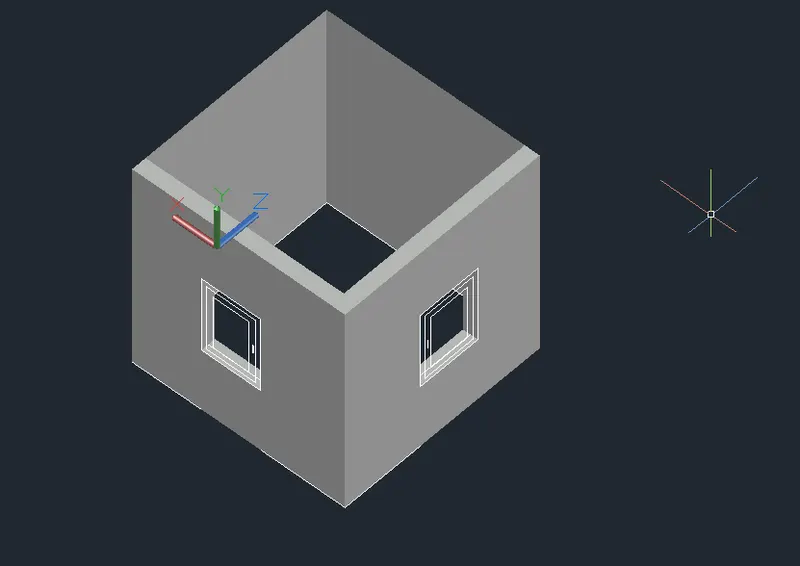
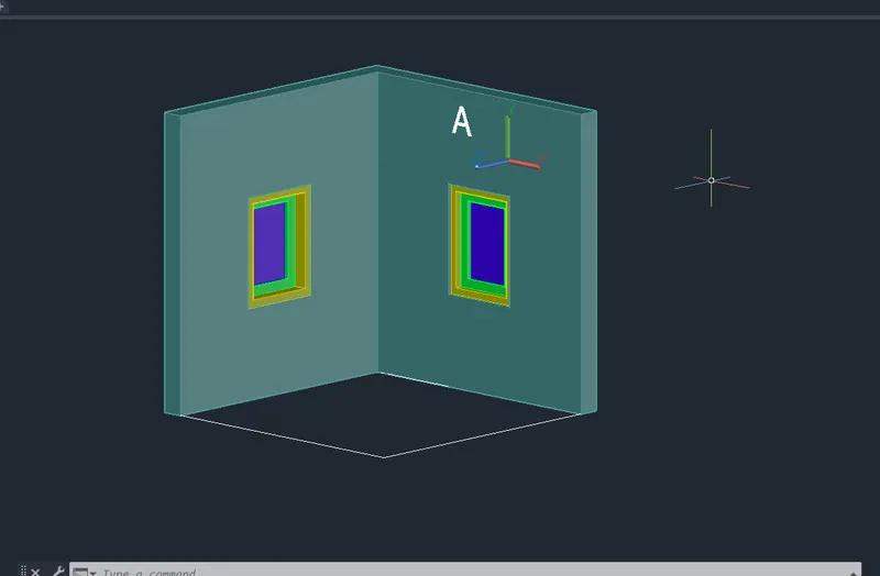
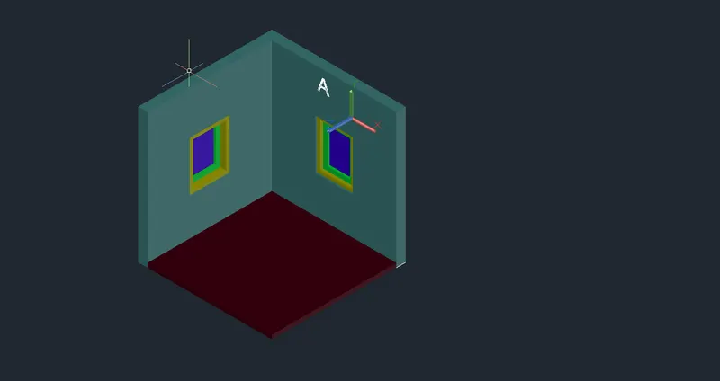
Result:
Drawing2:
Aim:
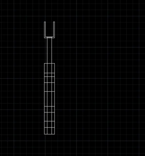
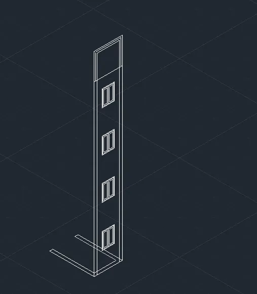
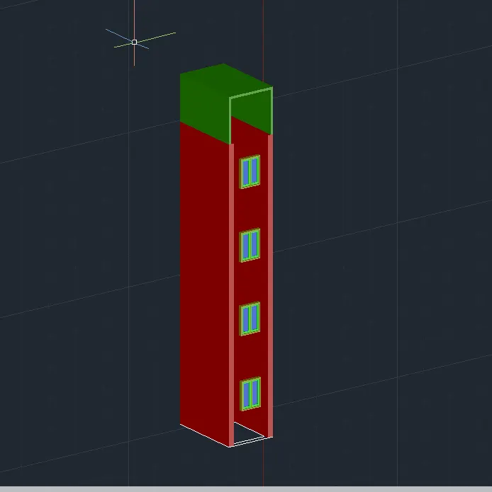
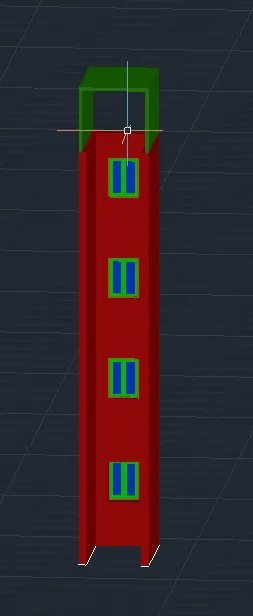
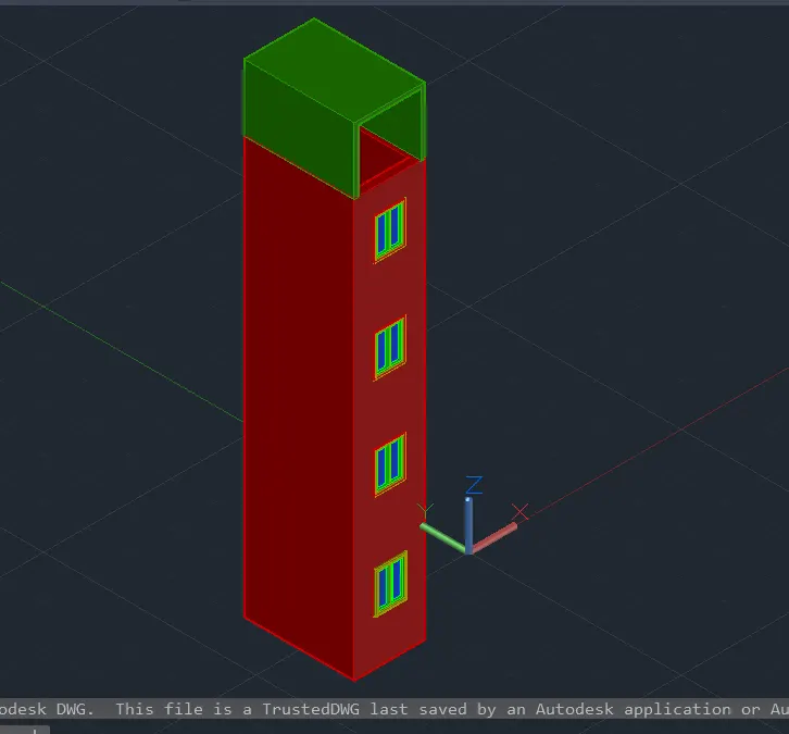
To Create the 3D View of the Building Façade as given in the plan and elevation.
Introduction:
The Plan and elevation of the building are drawn in 3D view by creating different layers , views ,including different building elements to make it an aesthetic apperance.
Procedure:
The plan and elevations are drawn with the given dimensions in 2D
They are taken to 3D modelling for the necessary changes
In this 3D Modelling
the Plan is made as the reference for the Elevation for Creating Bondaries.
The Elevation is rotated and the view is changed to isometric for visualization.
Commands used are
3D ROTATE: To rotate the objects into Isometric view
NEWVIEW : To create views for the Plan and elevation for further progress.
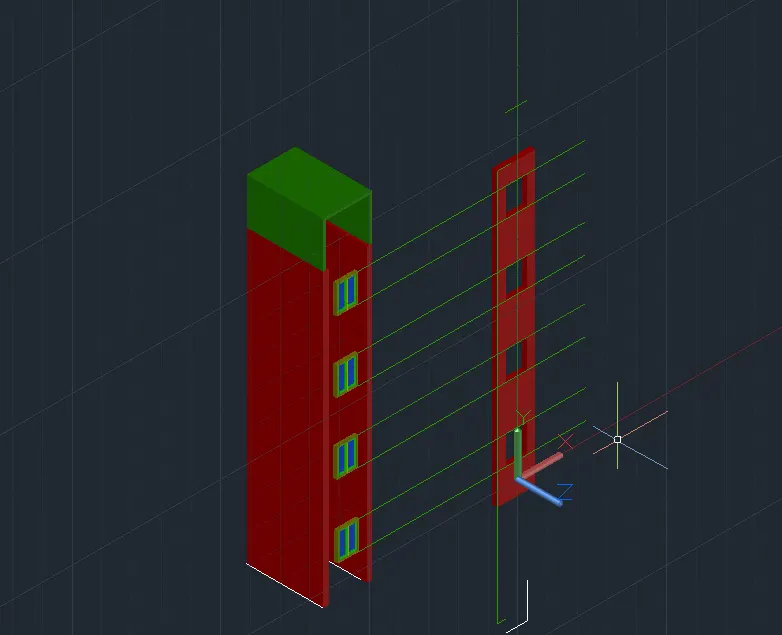
Now Boundaries are created for the Elevation.
Next the Regions are generated.
Commands used are
BOUNDARY : To create Boundaries for the closed objects
REGION : To make the planar objects
The Objects are Extruded for 3D visualization.
The unnecseccary or additional objects are subtracted as per the Extrusion requirements of the Objects.
Commands used are
SOLIDEDIT>EXTRUDE
SOLIDEDIT>SUBTRACT
Layers are created for the different elements in the building like
Windows,Window Frame,Window Mullion,Walls,Dimensions.
For the ease of the Drawing construction the layers are very much helpful.
Commands used are
LAYERS: To create layers for different Elements
The Coordinates are changed according to the position of the view that is required for operation in that Plane.
Coomands used are:
UCS>FACE>ACCEPTX or Y or Z or Zaxis are selected as per requirement.
The UCS command is activated for operation or for creating an element on the face of the Wall.
Later the Views with respect to coordinates are saved and named.
The walls are adjusted for making window units and they are inserted in the wall openings.
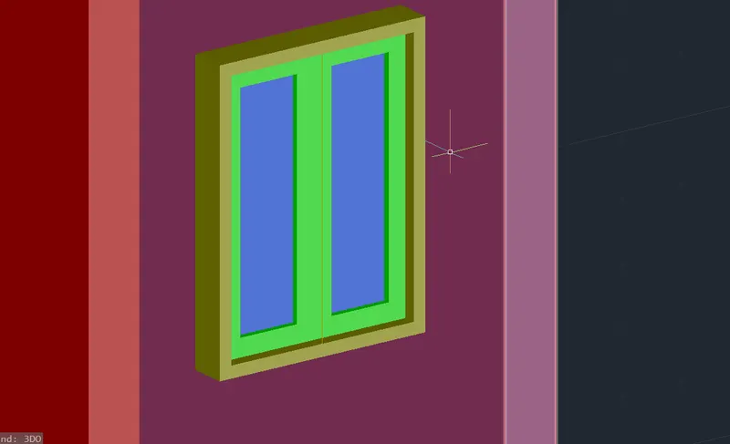
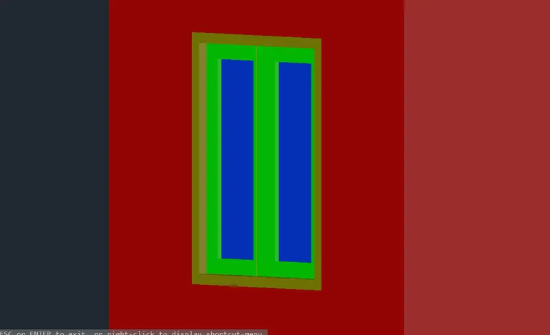
Then different colours for the elements of a Window are provided.
The window is extruded as per the given thickness.
The views are changed accordingly for different usage and ease of the construction of the Drawing.
The Views are named after their usage like V1,V2,V3...
All the elements are constructed using the above command sin different views respectively.
The Constructed elements can be adjusted using SOLIDEDIT commands
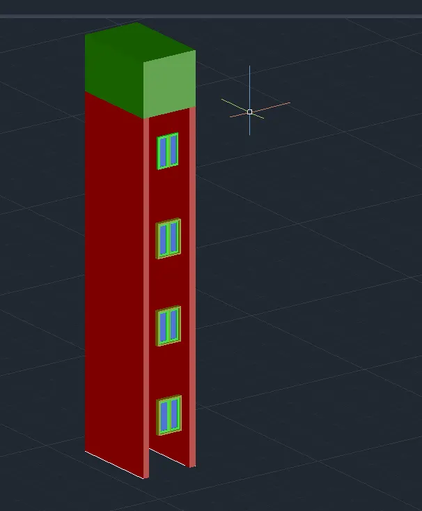
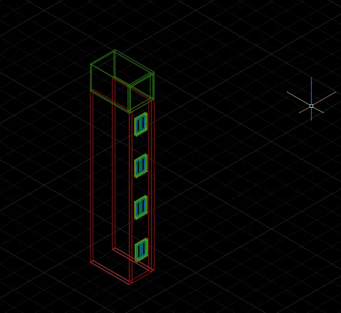
Result:
Drawing3:
Aim:
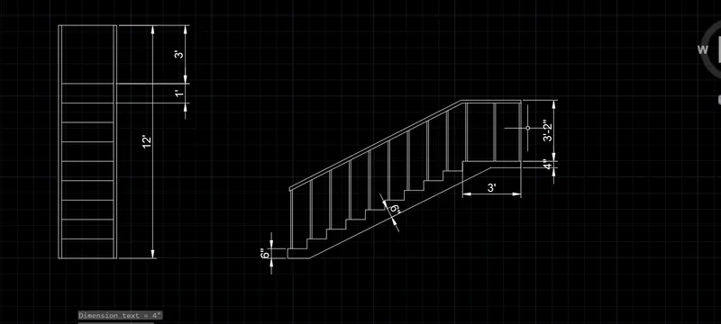
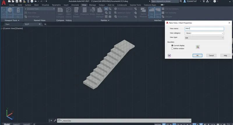
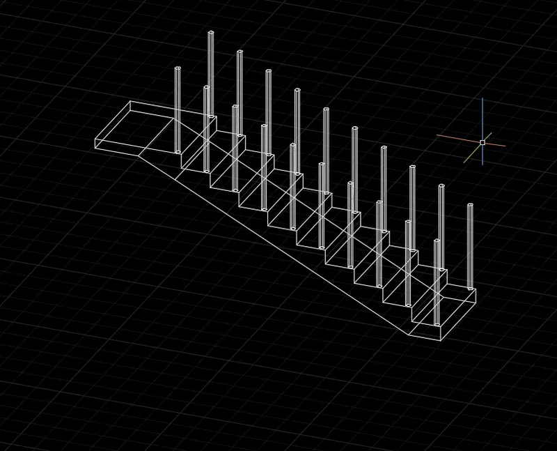
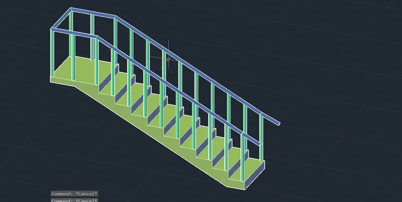
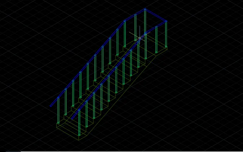
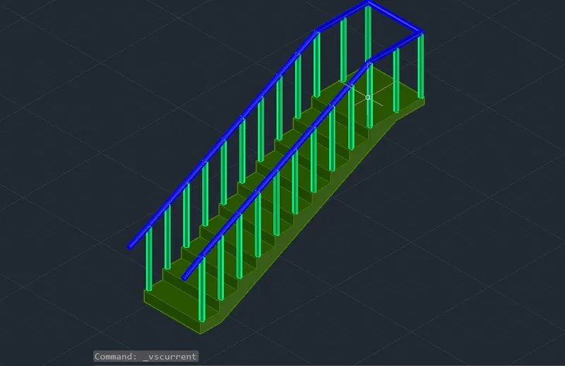
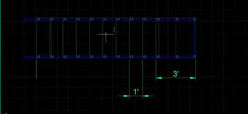
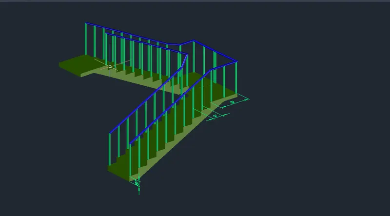
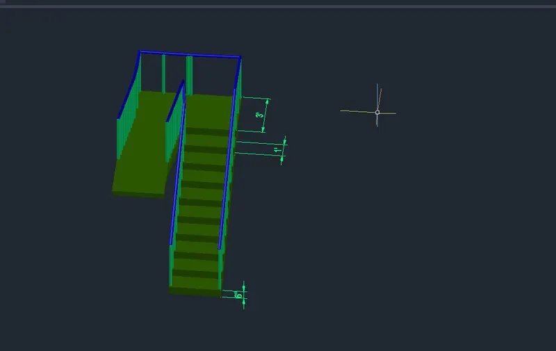
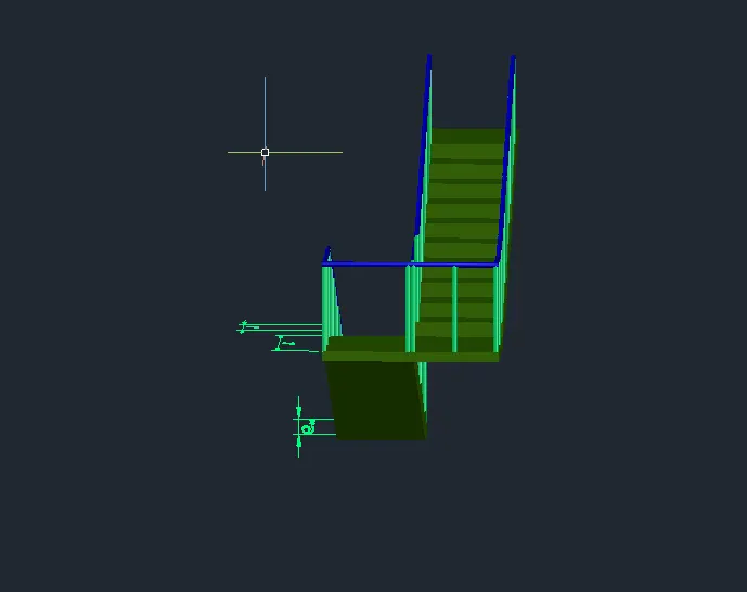
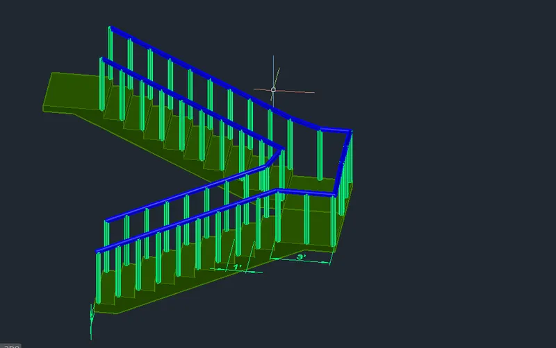
To Create the ismoteric 3d view of a stair with railing as shown in the plan and elevation with balustrades and the hand rails.
Introduction:
The Plan and elevation of the stair are drawn in 3D view by creating different layers , views ,including different building elements to make it an aesthetic apperance.
Procedure:
The plan and elevations are drawn with the given dimensions in 2D
They are taken to 3D modelling for the necessary changes
In this 3D Modelling
the Plan is made as the reference for the Elevation for Creating Bondaries.
The Elevation is rotated and the view is changed to isometric for visualization.
Commands used are
3D ROTATE: To rotate the objects into Isometric view
NEWVIEW : To create views for the Plan and elevation for further progress.
Now Boundaries are created for the Elevation.
Next the Regions are generated.
Commands used are
BOUNDARY : To create Boundaries for the closed objects
REGION : To make the planar objects
The Objects are Extruded for 3D visualization.
The unnecseccary or additional objects are subtracted as per the Extrusion requirements of the Objects.
Commands used are
SOLIDEDIT>EXTRUDE
SOLIDEDIT>SUBTRACT
Layers are created for the different elements in the stairs like RAISER AND TREAD,HANDRAIL,BALUSTRADES.
For the ease of the Drawing construction the layers are very much helpful.
Commands used are
LAYERS: To create layers for different Elements
The Coordinates are changed according to the position of the view that is required for operation in that Plane.
Coomands used are:
UCS>FACE>ACCEPTX or Y or Z or Zaxis are selected as per requirement.
The Balustrades are created by using the cylinder and it is copied in all the steps on both sides as well as in the landing.
Command used is CYLINDER
The Hand rails are drawn by using the line command, the top of the cylinder(Balustrades) are joined
Later by using sweep command the line is made as a hand rail after creating a circle object as a reference.
Result:
Drawing4:
Aim:
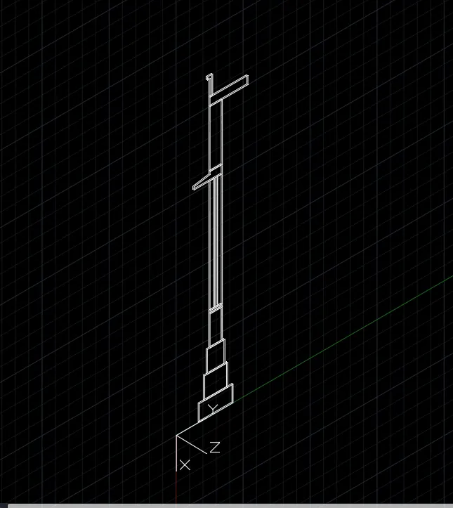
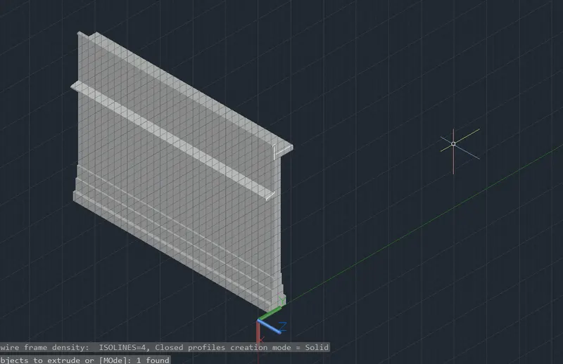
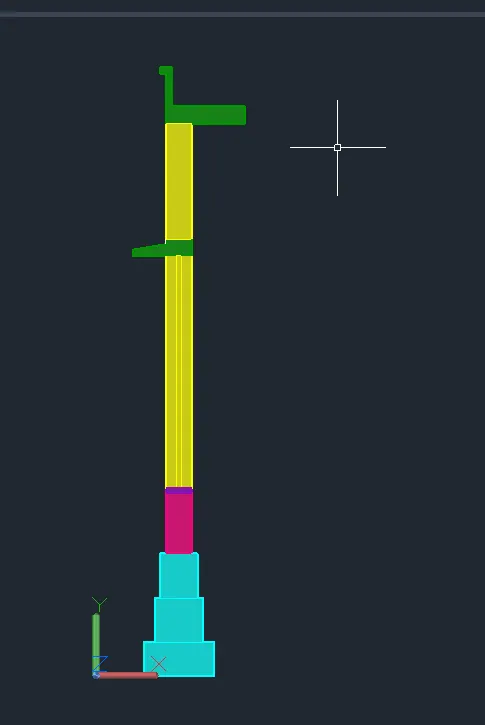
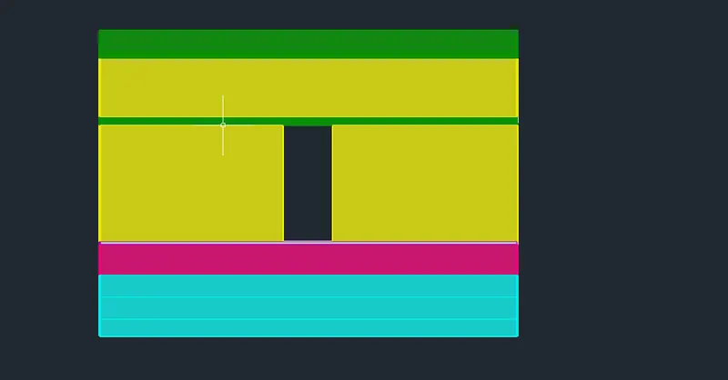
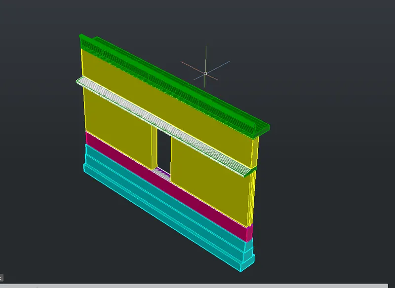
To Create the 3D view of a Wall with spread footing with the rendered view of the model and materials.
Introduction:
The Plan and elevation of the spread footing, the size of the parpaet and the coping are introduced.
Procedure:
The plan and elevations are drawn with the given dimensions in 2D
They are taken to 3D modelling for the necessary changes
In this 3D Modelling
the Plan is made as the reference for the Elevation for Creating Bondaries.
The Elevation is rotated and the view is changed to isometric for visualization.
Commands used are
3D ROTATE: To rotate the objects into Isometric view
NEWVIEW : To create views for the Plan and elevation for further progress.
Now Boundaries are created for the Elevation.
Next the Regions are generated.
Commands used are
BOUNDARY : To create Boundaries for the closed objects
REGION : To make the planar objects
The Objects are Extruded for 3D visualization.
The unnecseccary or additional objects are subtracted as per the Extrusion requirements of the Objects.
Commands used are
SOLIDEDIT>EXTRUDE
SOLIDEDIT>SUBTRACT
Layers are created for the different elements in the footing like
Stepped fooring,Plinth layer,Wall,Lintel roof,Roof.
For the ease of the Drawing construction the layers are very much helpful.
Commands used are
LAYERS: To create layers for different Elements
The Coordinates are changed according to the position of the view that is required for operation in that Plane.
Coomands used are:
UCS>FACE>ACCEPTX or Y or Z or Zaxis are selected as per requirement.
The UCS command is activated for operation or for creating an element on the face of the Wall.
Later the Views with respect to coordinates are saved and named.
The walls are adjusted for making Door units and they are inserted in the wall openings.
The views are changed accordingly for different usage and ease of the construction of the Drawing.
The Views are named after their usage like V1,V2,V3...
All the elements are constructed using the above commands in different views respectively.
The Constructed elements can be adjusted using SOLIDEDIT commands
The Dimensions are mentioned as per the given drawing.
Command used are
DIMSTYLE
DIMLINEAR
To mention Dimensions in the respective coordinate of the element again the UCS command is used.
Later Rendering of the elements is done
Command used is
RENDER or RR
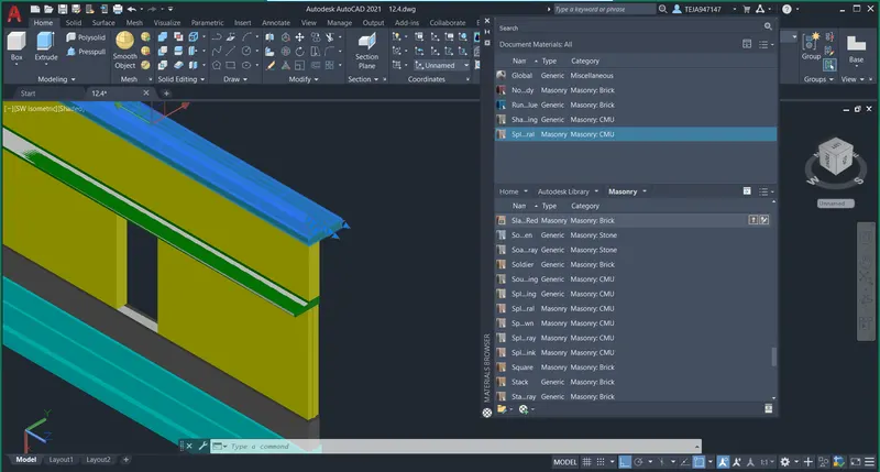
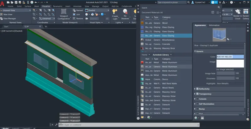
The material properties are given using commands like
MATERIALBROWSER
MATERIAL MAPPING
The Suitable Material is given accordingly for all the Building elements.
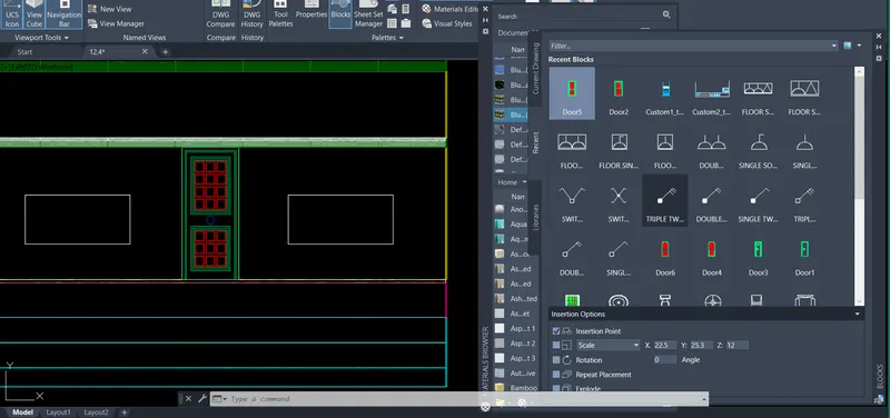
Result: