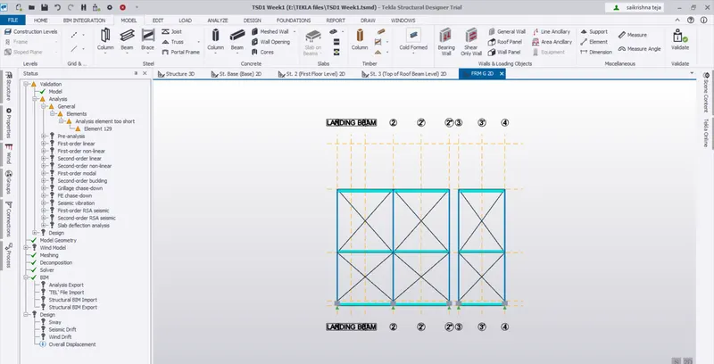
Week 3 Challenge
Details of the Structure:
Support = Fixed-Fixed (Top and Bottom)(Mx and My will be formed)
Concrete Pedestal Size PD1 = 600mm *600 mm
Steel Column C1 = MB300
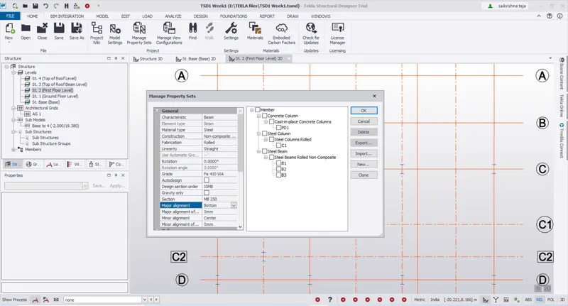
Steel Beams
B1= ISMB 300 applied for Primary Beams at Ground Floor including Staircase landing Beam
B2 =ISMB 250 applied for Secondary Beams at Ground Floor
B3 =ISMB 250 applied for Primary Beams at First Floor including Staircase landing Beam
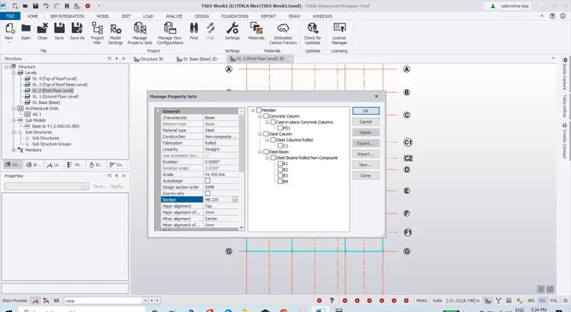
B4 =ISMB 225 applied for Secondary Beams at First Floor
B5 =ISMB 350 apllied for the Roof Beams along the Ridges and also below the Rafters
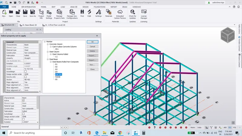
RAFTER =MB 400 applied along the Grids 1,2,2",3,4 on the Roof
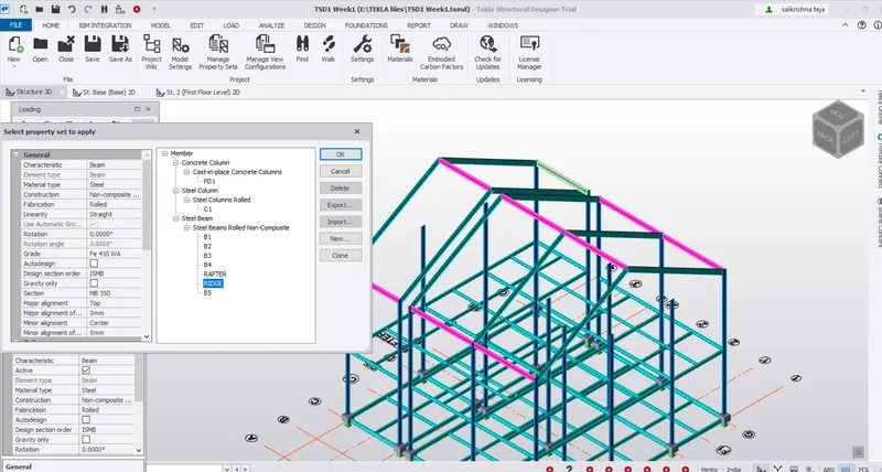
RIDGE =MB 400 applied along the Grids 1,2,2",3,4 on the Roof Beam top level horizontally in X direction
MB 400 applied along the Grids C,Ridge,G on the Roof Beam top level horizontally in Y direction
1. Create beam properties for First floor and model the beams
Answer:
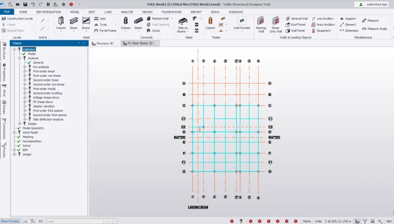
1.Ground Floor plan for the adjusted view in 2D
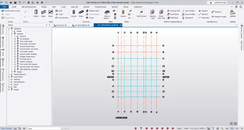
2.First Fllor Plan view
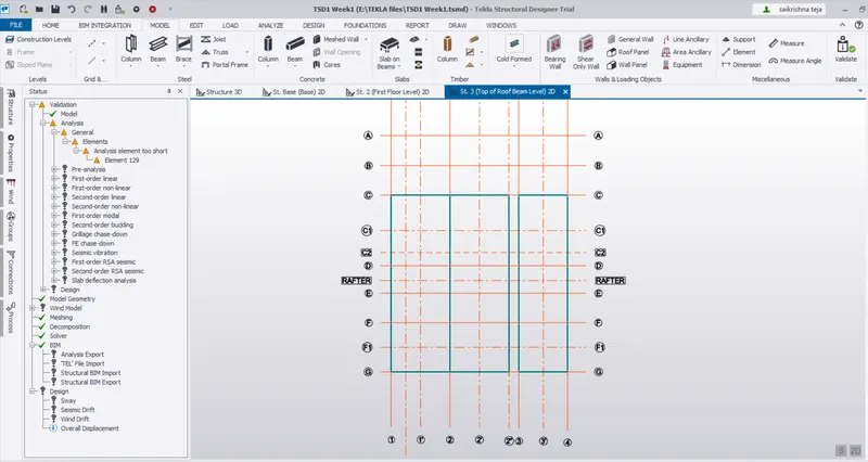
3.Second Floor plan view = Top of Roof Beam view
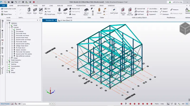
4.Structure in 3D view
5. Selecting Beam in Manage property sets>Member>Beam B3
6.Selecting Beam in Manage property sets>Member>Beam B4
2. Create rafter beam on second floor as roof and moment frame action in one direction and add bracings at locations as per the design intent
Answer:
7.Selecting Beam in Manage property sets>Member>Rafter
8.Selecting Beam in Manage property sets>Member>Ridge
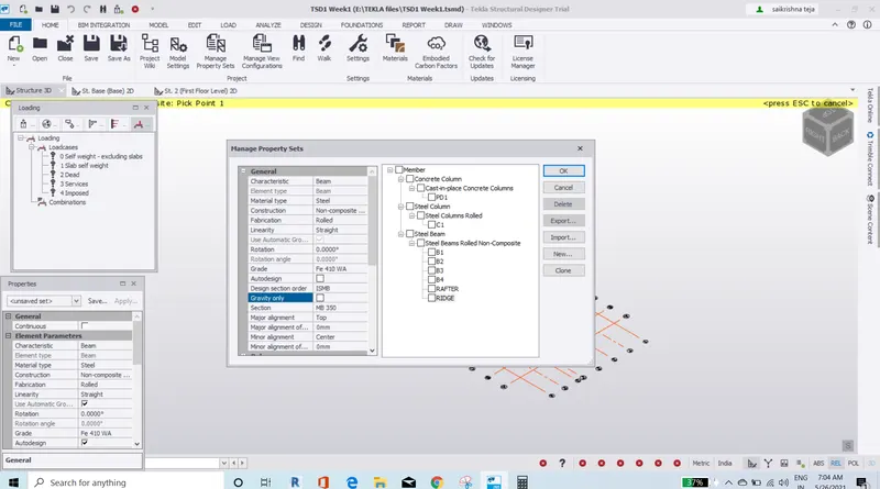
9.Placing Rafters
10.Placing Ridges
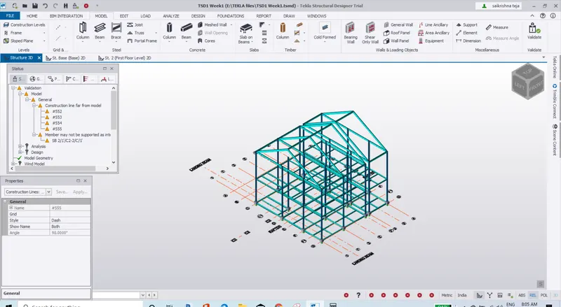
11.View after placing Rafters and Ridges
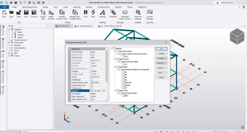
12.Selecting Beam in Manage property sets>Member>Bracings
13.Placing X Grids in Frame 1
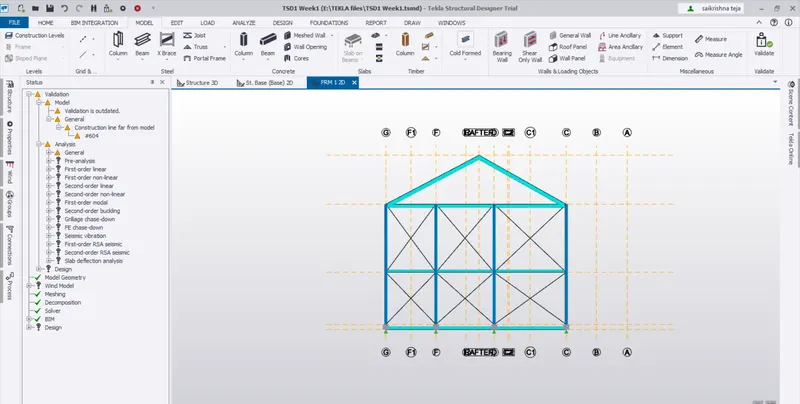
13.Placing X Grids in Frame G