Creating a 3D rendered model for a Residential Building in AutoCad
Aim:
To Create a 3 dimensional model of the residential building with a rendered view.
Introduction:
Building drawn in 3D modelling is helpful to get the imaginative picture of the whole Design and outlook, It helps in making and also improvising the views and design of the structures, by comapring,making,checking with different Probabilites and combination of materials.
Procedure:
Create Plan of the Building having wall thickness of 230mm including the Doors and Windows.
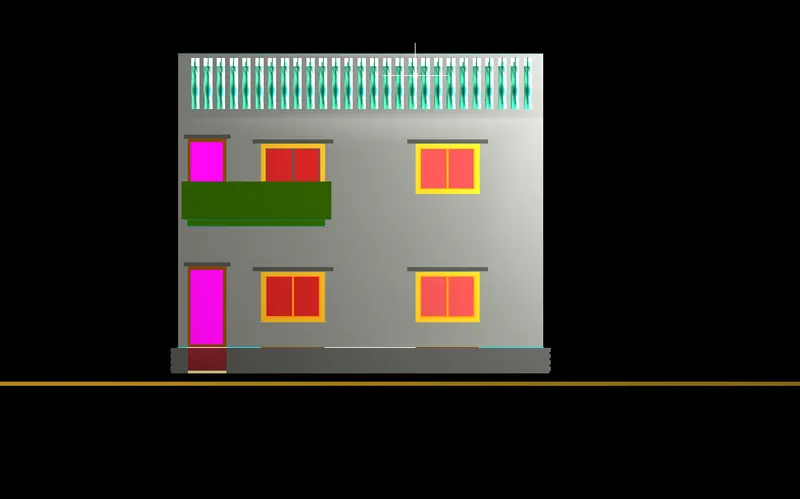
Elevation view is created by drawing the construction line from the Plan.
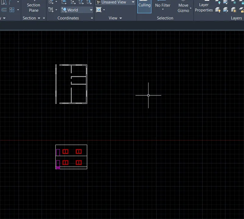
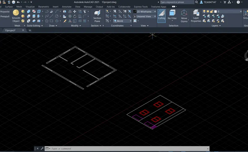
Make Layers for the elements in the Building.
Layers are
3D wall
3D window Frame
3D window Mullion
3D window Glass
3D Door
3D Door Frame
3D Door Panel
3D Floor
Get the Isometric view of the Building to startwith.
Put 3D wall Layer "ON"
Go to Boundary>Pick point>Region>Enter.
The commands used are
Command : BO for Boundary
Command :REG for region
Get the Height of the floor from the Plinth Level in Elevation.
Make a view by using Command:VIEW MANAGER 3D Isometric view save it.
Command: EXTRUDE Extrude the walls of the height upto Roof Level as per Elevation(say 3000mm)
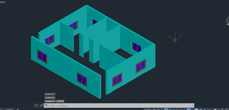
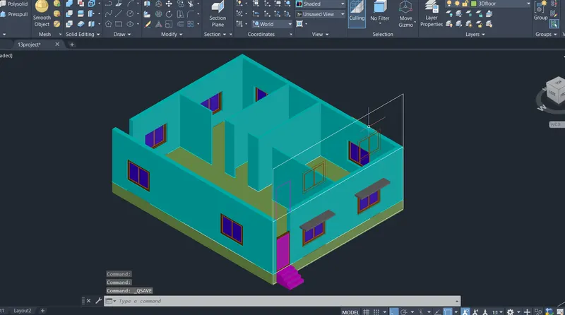
Use Command: PLAN for changing the views and checking with the PLAN of the building.
Use Command:UCS for changing the Coordinates according to the Workspace.
Now Put the Windows and Doors in the Openings of the walls (between the walls)
Extrude the walls below the window and above the window by creating a Rectangle>Region>Extrude.
Extrude the wall above the Door by creating a Rectangle>Region>Extrude.
Make union all the 3Dwalls created by using Command : UNION (SOLIDEDIT>UNION)
Copy the Elevation and make roation in XZ axis using Command : 3DROTATE
This view is helpful for derivation of the DoorFrame,Door panels and Window Frames,Window Panels.
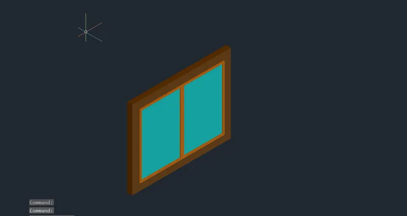
The windows elements are assigned to the respective Layers (Window Frame,Window Muillion,Window Glass)
Later region is created for each of the Window element and Extrude them acoording to the respective Layers and colours associated with the Layers.
All the windows are made by following the above Procedure.(say Window Frame thickenss=75mm,Window Mullion thickness=35mm,Window Glass thickness=15mm).
The windows elements are combinded to form a Group for each and individual window, using Command : GROUP.
The elements are placed in the respective Layers and they are assigned with colours associted with the Layers.
Then Region is created and Extruded, (say Door Frame thickness=75mm,Door panel thickness=30mm,Door thickness=120mm).
The Door elements are combinded to form a Group for each and individual Door, using Command : GROUP.
Now make the Flloor and Plinth by creating a Rectangle Below the wall.
To have the view below the wall, the other layers are put OFF use Command : LAYOFF.
or also use can make the isolation of the Floor and Plinth using the command : LAYISO after creating them seperatly and attached at the point required.
The Rectangle created is made Boundary>Region>Extrude.
The Floor created is put in the respective layer created with the name 3DFloor.
(Say the Floor and plinth combined Thickness=600mm).
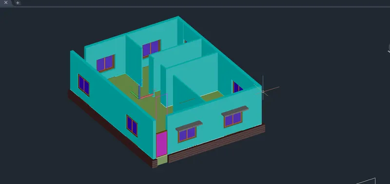
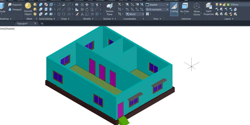
A Design is created for the plinth to have an asthetic look by using rectangle and Design is made using lines, use
Command : LINE,
later the Design is made as a Boundary>Region>Extrude to the path associated with the Plinth surrounding.
A new Layer is created and named as PROJECTIONS for the projections over the Door and Window.
The Projections are attched over the Door and window for the Length=450mm(say),Thickness=110mm(say).
3Dsolids are created for every 2D created using the above commands and using the way Boundary>Region>Extrude.
sometimes Command : SOLIDEDIT is used for making different operatons for the solids created.
The path is SOLIDEDIT>SUBTRACT.
To have the views chaning according to the drawing the commands used are
Command : 2DWIREFRAME
Command : HIDDEN
Command : SHADE
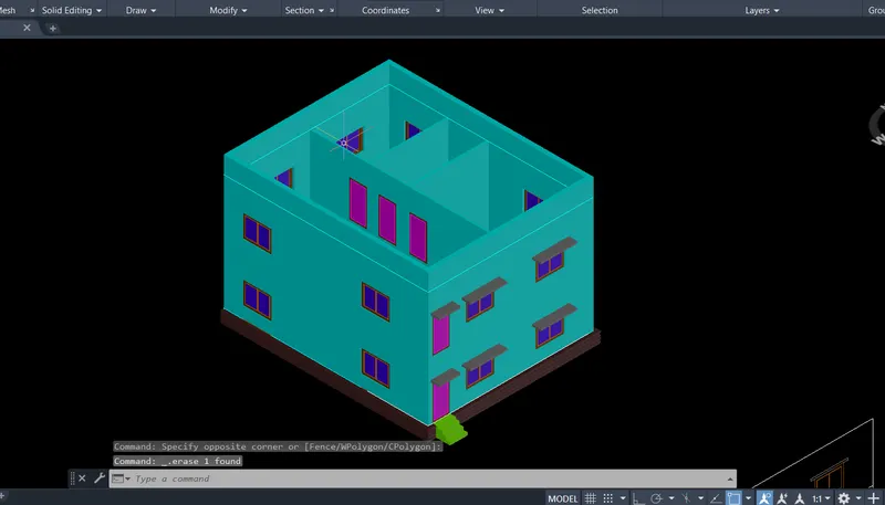
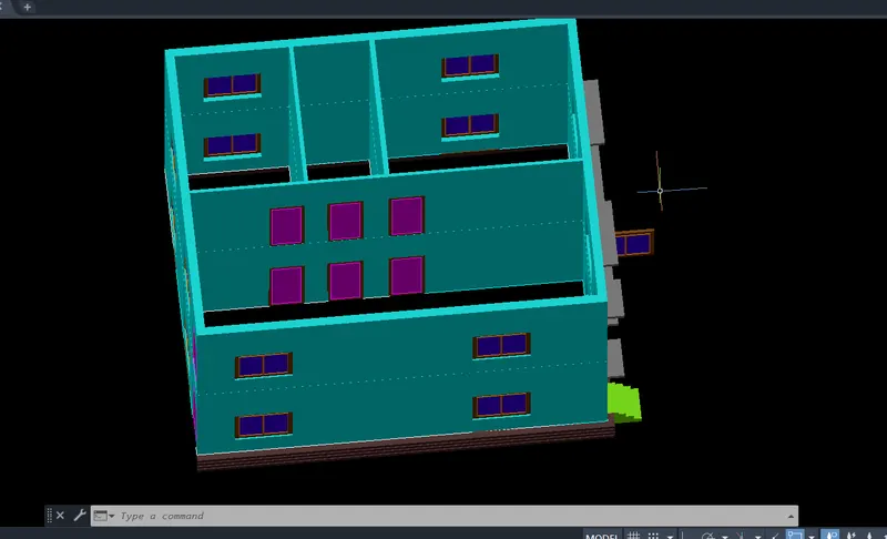
First Floor:
Now Copy the walls of the Ground floor and attach them to the first floor.
The Ground slab is made by using rectangle and Boundary>Region>Extrude.
Say the thickness of slab=150mm
The slab is introduced in the Floor Layers and all the properties of the Floor are matched.
All the Doors and windows with Projections are selected and copied to the Firstfloor.
Parappet wall:
The parrapet wall is created by Extracting the edges of the First floor slab
Command : EXTRACT EDGES; the edges are Extruded to a height of 900mm(say).
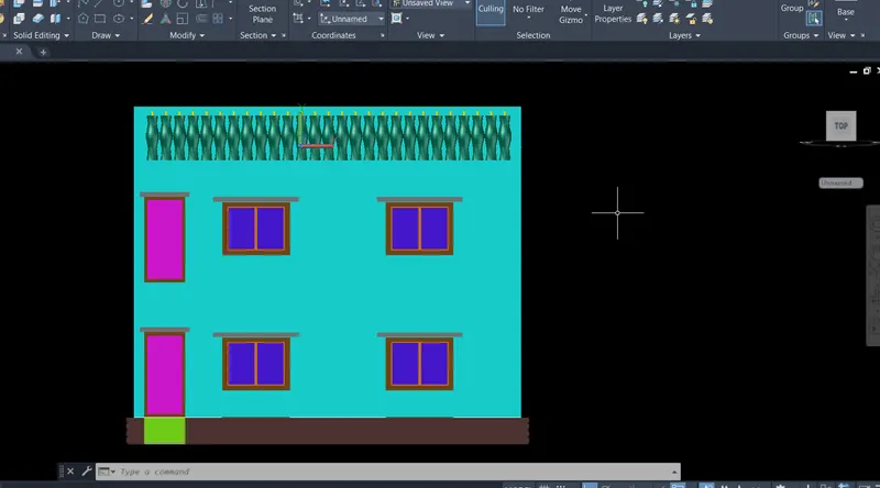
A design is made for the Parappet wall by creating some holes (Command : SUBTRACT) SOLIDEDIT>SUBTRACT.
Then Balustrades are made using circles at different elevations and they are Lofted
Command : CIRCLE
Command : LOFT
We can also create a Block for the Balustrades and Insert them
Commands : BLOCK
Commands : INSERT
The Balusrades are attached in to the holes made in the Parappet wall by using commands
Command : ARRAY
Command : EXPLODE
The Balustrades after creating and attaching them to the holes of the parappet wall they are made disassociate.
They are disassociated using the command Explode.
Now some Panels are to be attached to the wall of the First floor Elevation they are represented as a Design.
The Design is made using Rectangle>Boundary>Region>Extrude.
Finally the Building basic things are done .
Now the Cameras are introduced to the Views and Materials are assigned.
To place a camera a cylinder is made and the camera is fitted over the cylinder
Command : CYLINDER
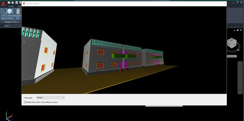
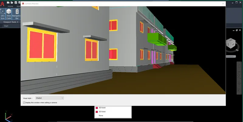
Command : CAMERA (VISUALISE>CAMERA)
Pick a Camera place to get the view
Name the Camera
Give the Height for the Camera
Adjust the Lens of the Camera
Give the Target location to the camera.
Now the Camera is set.
Click on the Camera to get the view.
Adust the views using VIEWMANAGER with the views like (V1,V2,..Cam1,Cam2..)
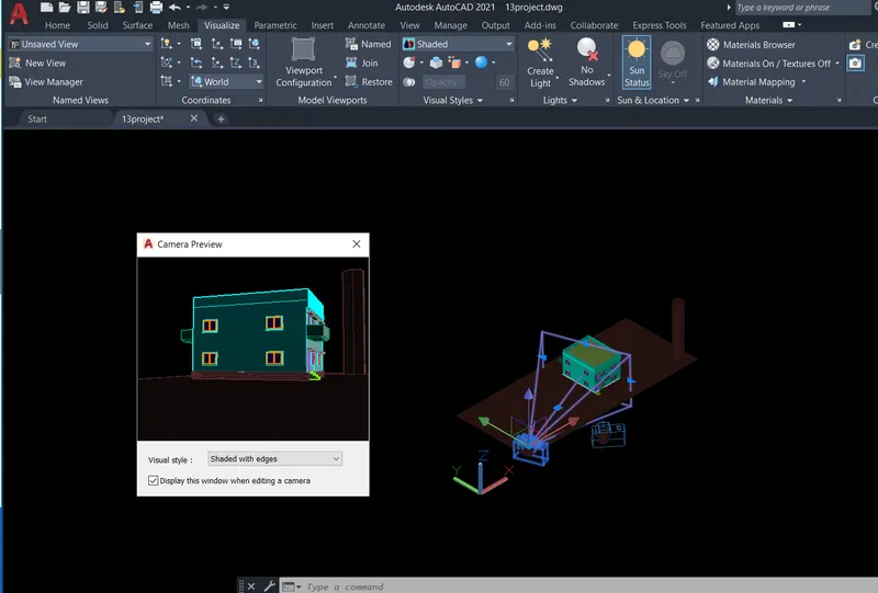
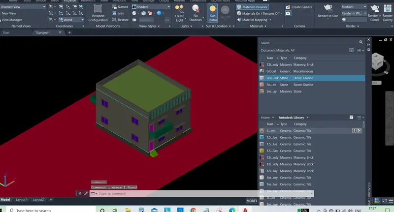
Now we can use the Sunstatus to get the views highlighted with some light
Command: SUNSTATUS (Visualise>Sunstatus)
Use Navigationwheel for having different views of ZOOM,PAN,ORBIT,REWIND etc..
Command : NAVSWHEEL
Now put the lights at a certain height for getting a good look.
Command: POINT LIGHT
Command : SPOTLIGHT
Command : DISTANTLIGHT
Command : WEBLIGHT
Anyone of the above are selected and placed over a cylinder at certain height.
We can change the Properties of the Light by Rightclicking on the Light
Properties that can be changed are Name,Intensity factor,Lap intensity,Lamp colour....
Now the materials are assigned for all the elements of the Building.
Go to Material Browser,select and add the material required for diiferent elements,
Command : MATERIALBROWSER
Stone material assigned to the walls,steps,Certain design over the wall, design of the plinth
Metallic paint is assigned to the Door frames,Window frames
Steel or concrete material for the Balustrades and Handrails
Glass for the window glasses..
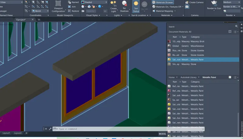
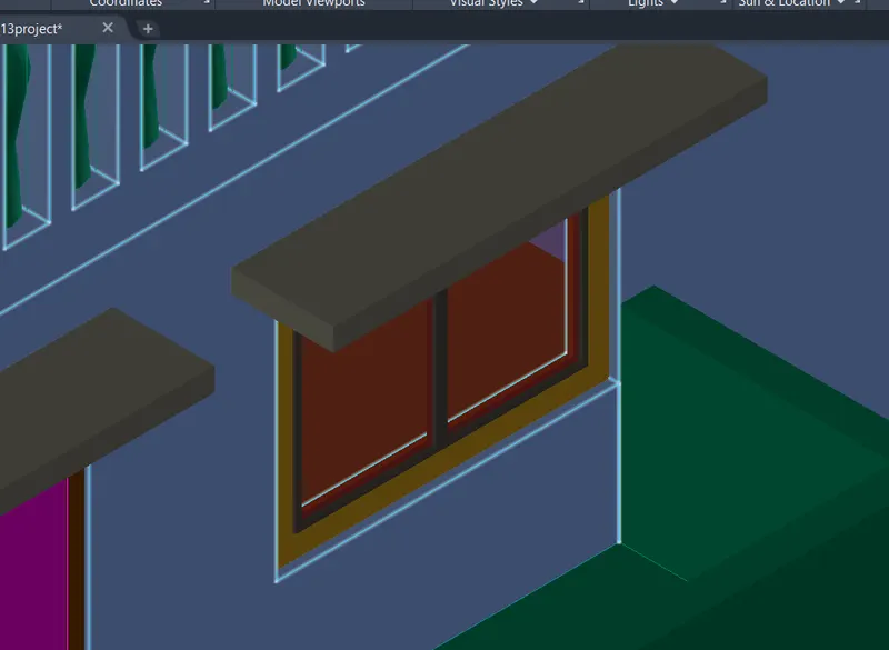
Command : MATERIALMAPPING
This is used for the Mapping the material and have the new image insertion also to create the Generic ersion of the materials.
Command : SETUV
This command helps in adjusting the material designs for different elements.
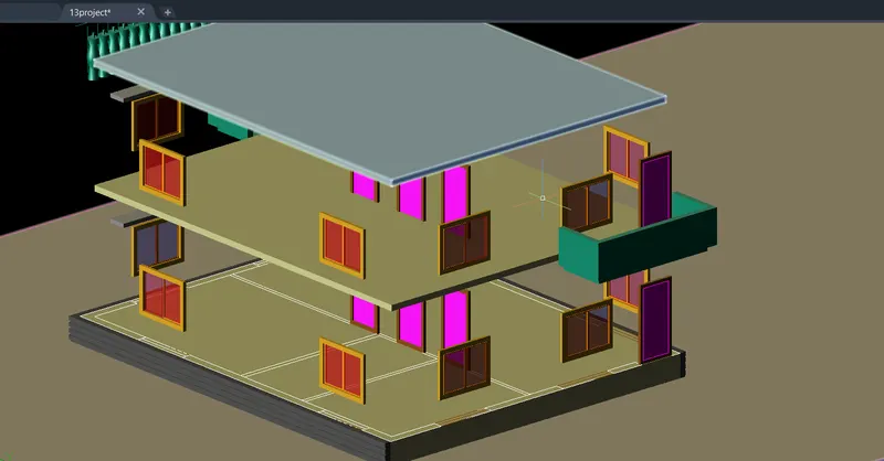
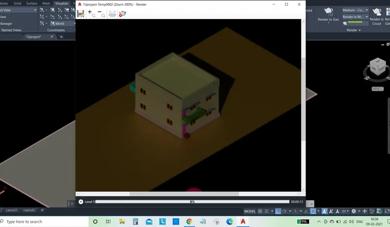
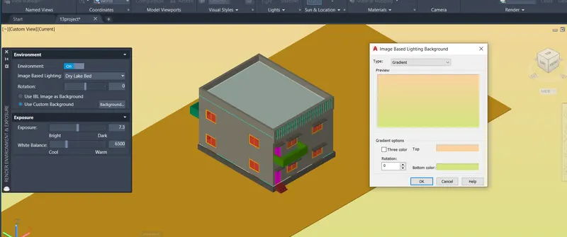
RENDERING:
Command : RR
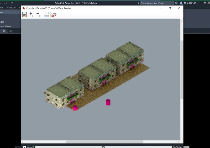
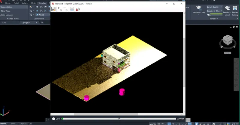
The rendering of the Whole building is done to have the
view of the assigned materials, assigned light,
View from the Camera required
We can adjust the Background settings from the presrt manager
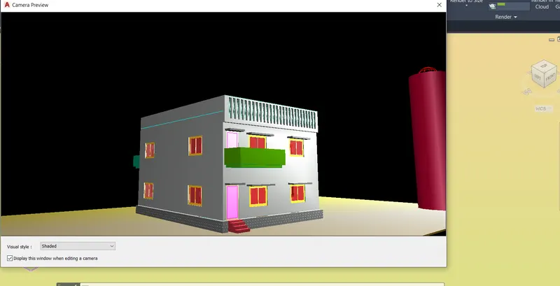
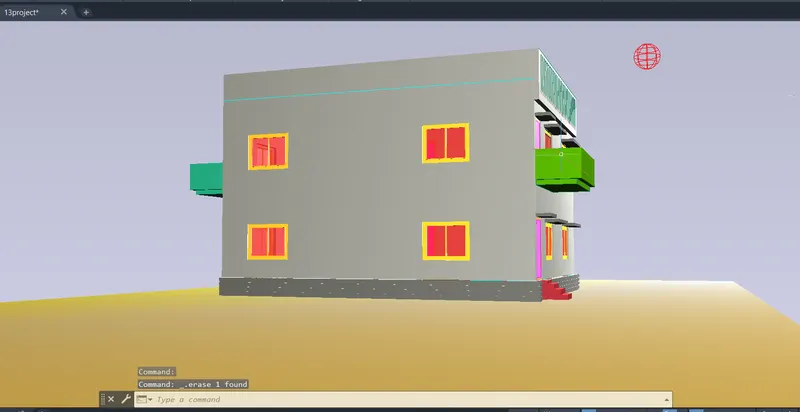
Command : PRESETMANAGER
Finally we can get the Rendered view of the Building through the Output file,
After completion of the Rendering we can save the Output file as JPG or PDF.
Result: