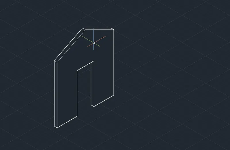
Creating various 3D Models like Furniture, Footing, Girder, Column drop with panel and Gable Wall in AutoCad
Drawing1:
Aim:
To draw the given 3D object(Furniture element) in 3D basics.
Introduction:
The Object is drawn as per the given dimension and to have the multiple views in 3D.
Procedure:
The object assesment is done to create all the views possible.
Drawing of the element is started once the UCS is made ready
UCS ICON is tapped into 3D view XYZ with the help of Navigation Bar or View Cube.
Orthogonal is kept On,to understand the movement of the Line in the respective Coordinate axes
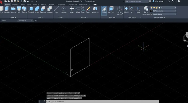
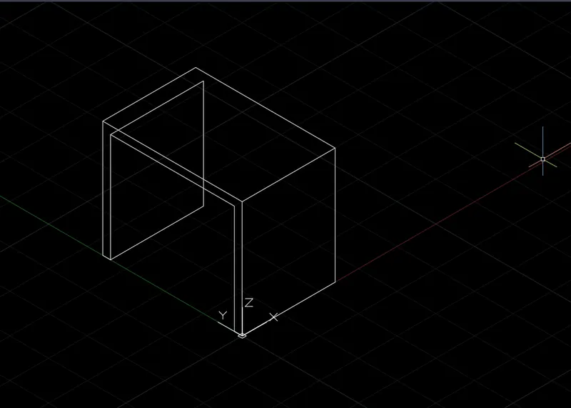
Now the drawing is started with the LINE command & OFFSET command.
The lines are drawn with the given dimension.
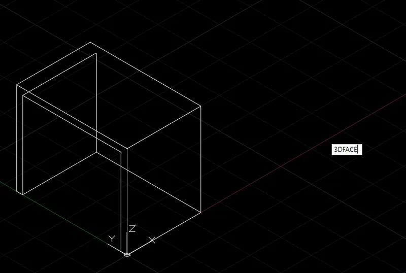
To make the lines hidden the command used is 3DFACE.
The corners of the face are joined and Hidden lines are made.
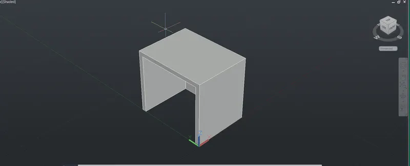
SHADED VIEW gives the clear image of the FACE.
The views are roatated and observed in 3DORBIT Command to recheck them.
Finally the required diagram is established.
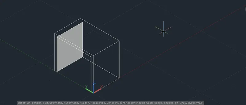
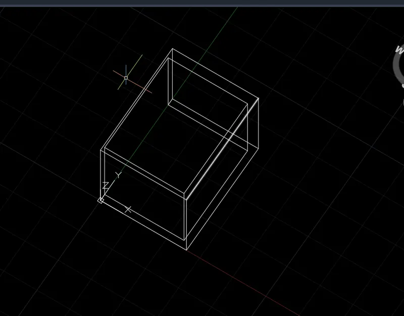

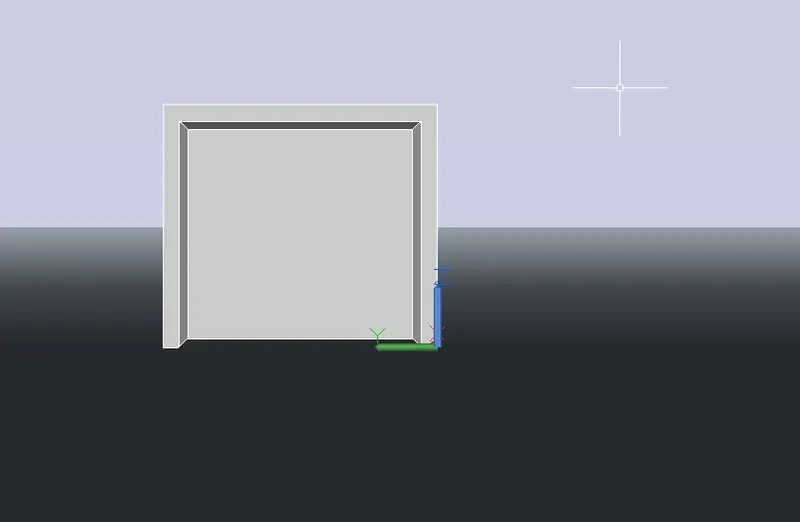
Result:
Drawing2:
Aim:
To draw the given 3D Model Isolated Footing in 3D basics.
Introduction:
The Object is drawn as per the given dimension and to have the multiple views in 3D.
Procedure:
The object assesment is done to create all the views possible.
Drawing of the element is started once the UCS is made ready
Ucs icon is tapped into 3D view XYZ with the help of Navigation Bar or View Cube
Orthogonal is kept On,to understand the movement of the Line in the respective Coordinate axes
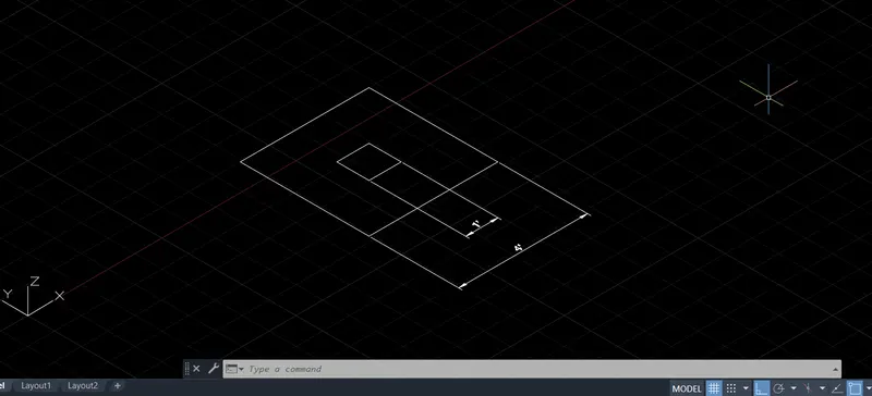
Now the drawing is started with the Line command & Offset command.
The lines are drawn with the given dimension.
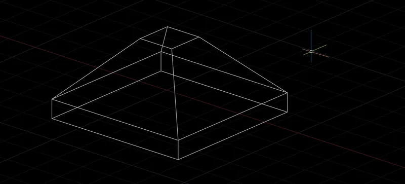
To make the lines hidden the command used is 3DFACE.
The corners of the face are joined and Hidden lines are made.
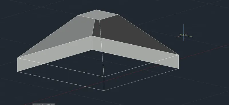
SHADED VIEW gives the clear image of the FACE.
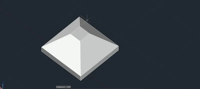
The views are roatated and observed in 3DORBIT Command to recheck them.
Finally the required diagram is established.
Result:
Drawing3:
Aim:
To draw the given 3D View of AASTHO Type Girder in 3D basics.
Introduction:
The Object is drawn as per the given dimension and to have the multiple views in 3D.
Procedure:
The object assesment is done to create all the views possible.
Drawing of the element is started once the UCS is made ready
Ucs icon is tapped into 3D view XYZ with the help of Navigation Bar or View Cube.
Orthogonal is kept On,to understand the movement of the Line in the respective Coordinate axes
Now the drawing is started with the Line command & Offset command.
The lines are drawn with the given dimension.
To make the lines hidden the command used is 3DFACE.
The corners of the face are joined and Hidden lines are made.
SHADED VIEW gives the clear image of the FACE.
The views are roatated and observed in 3DORBIT Command to recheck them.
The object is rotated in the 3D view using the command 3DFORBIT.
Finally the required diagram is established.
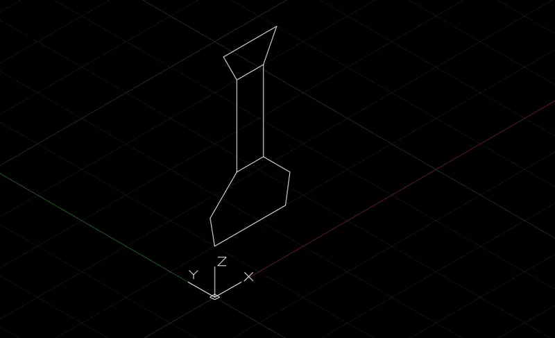
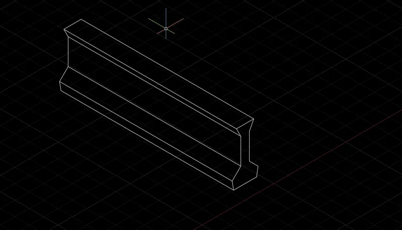
Result:
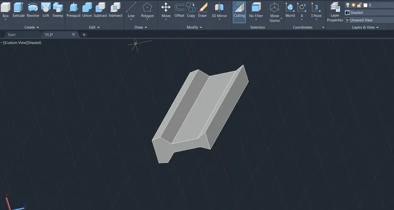
Drawing:4
Aim:
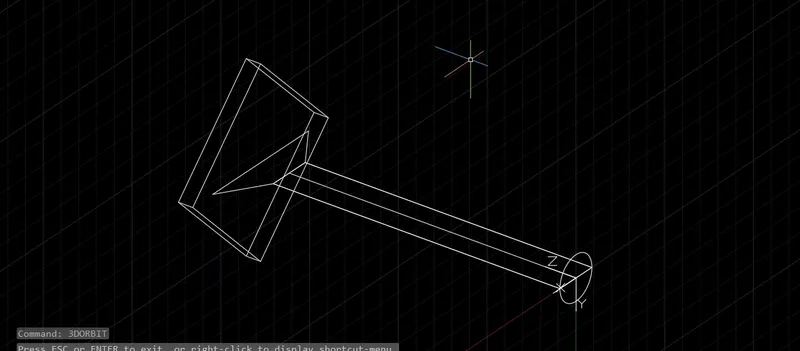
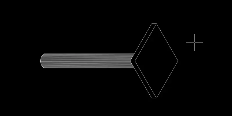
To Create a 3d Model of a drop column with panel as shown in section and isometric view.
Introduction:
The Object is drawn as per the given dimension and to have the multiple views in 3D,The section and the Front view are to be drawn.
Procedure:
The Procedure for the Drawing in the Sectional view can be drawn in 2D also.
Commands used for drawing the 2D view are
Line commnad
Rectamgle command
Dimlinear command
Then the Procedure for the Drawing the Isometric view is taken in 3D Basics.
The object assesment is done to create all the views possible.
Drawing of the element is started once the UCS is made ready
Ucs icon is tapped into 3D view XYZ with the help of Navigation Bar or View Cube.
Orthogonal is kept On,to understand the movement of the Line in the respective Coordinate axes
Now the drawing is started with the Line command & Offset command.
The lines are drawn with the given dimension.
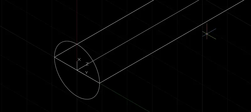
To have the surface mesh the command used is RULESURF.
The Command SURFTAB1 is used to increase the no of mesh lines.
For this the lines are selected first later the arc and the other edge is selected to make the required RULESURF.
Finally the required diagram is established.
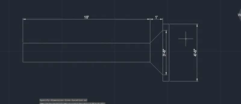
Result:
Drawing5:
Aim:
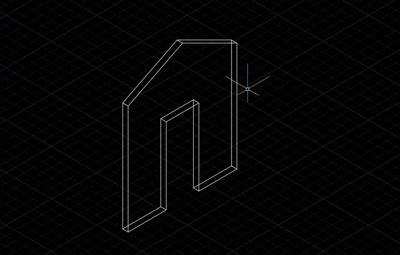
To draw the given 3D model of the Wall having Wall thickness as 9inches in 3D basics.
Introduction:
The Object is drawn as per the given dimension and to have the multiple views in 3D.
Procedure:
The object assesment is done to create all the views possible.
Drawing of the element is started once the UCS is made ready
Ucs icon is tapped into 3D view XYZ with the help of Navigation Bar or View Cube.
Orthogonal is kept On,to understand the movement of the Line in the respective Coordinate axes
Now the drawing is started with the Line command & Offset command.
The lines are drawn with the given dimension.
To make the lines hidden the command used is 3DFACE.
The corners of the face are joined and Hidden lines are made.
SHADED VIEW gives the clear image of the FACE.
The views are roatated and observed in 3DORBIT Command to recheck them.
Finally the required diagram is established.
Result: