Structural Modelling using Etabs 2018
Answer:
- Typical floor plan – The location and thickness of the brick walls and the use of the
space (for estimating live load) can be obtained from this plan - A building section through the staircase and lift core is provided
- Parking layout in the ground floor – the column/shear wall arrangement must not
obstruct entry/exit of vehicles.
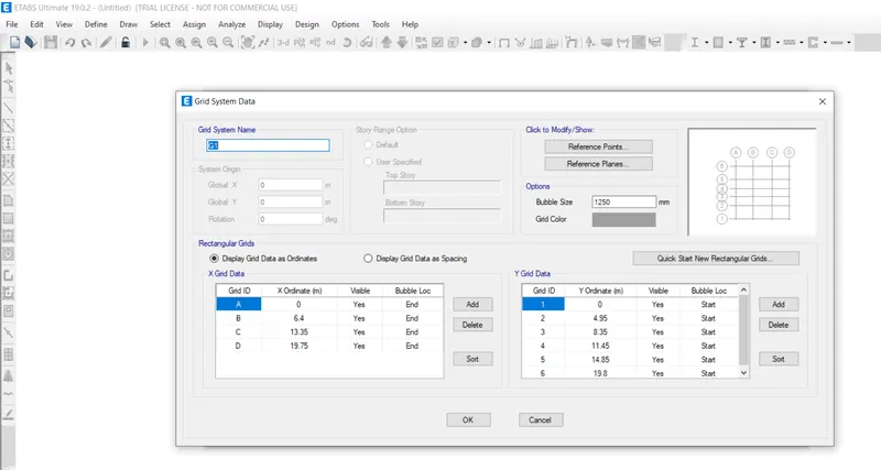
STEP 1: Grid data
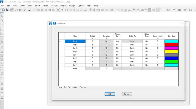
STEP 2: Storey data
Step 3: Material properties
COLUMNS
BEAMS
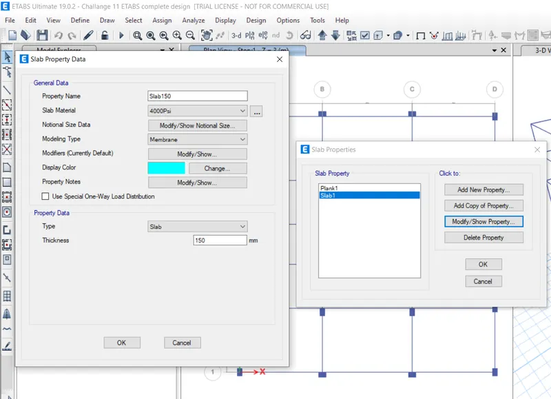
SLABS
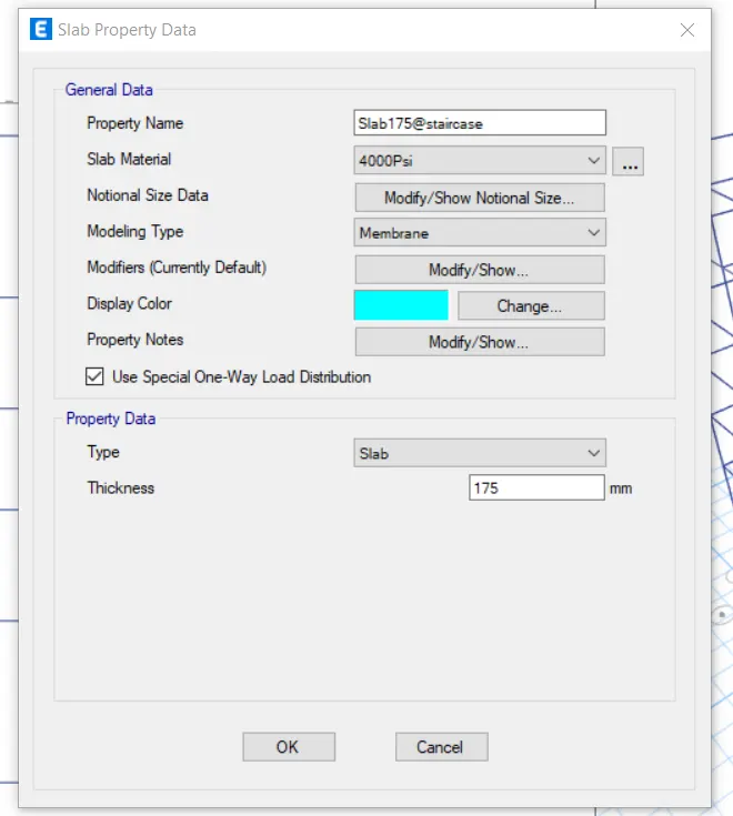
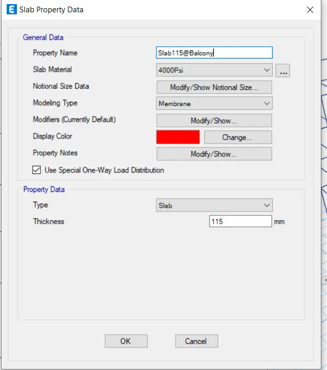
SHEAR WALL
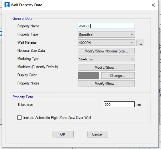
STEP 4: Changing Orientation and adjustment of shear walls and columns accordingly
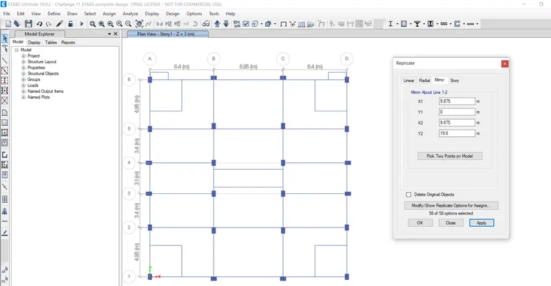
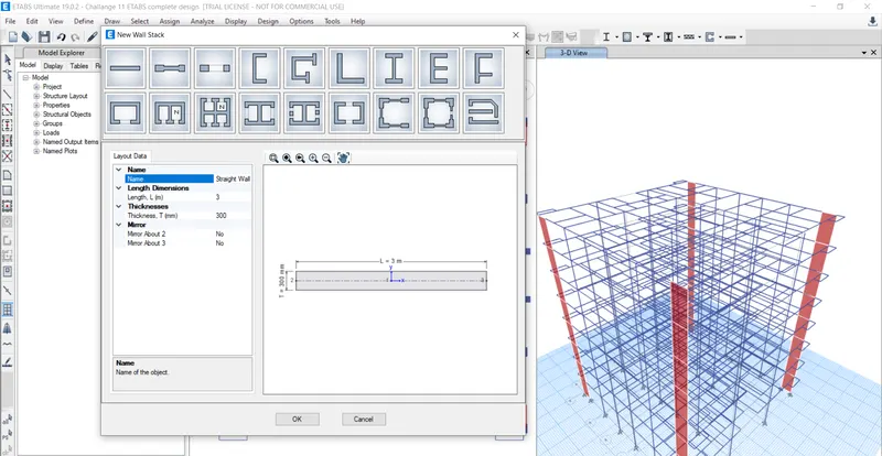
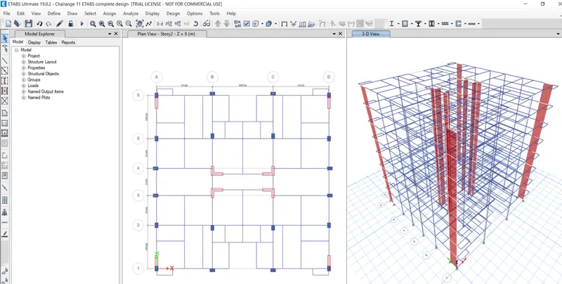
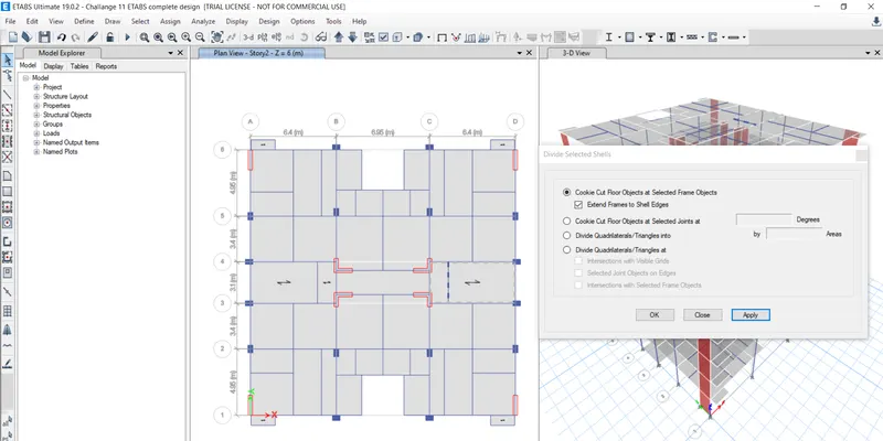
STEP 5 : Adjustment of slab sections
STEP 6 : Providing support = Fixed support
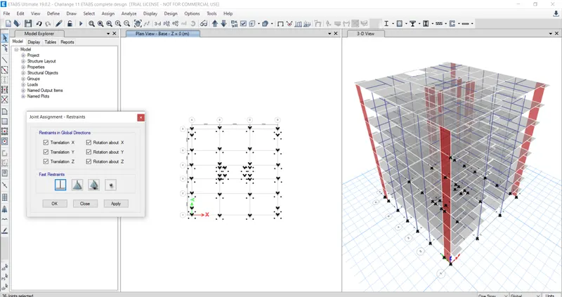
View of sections
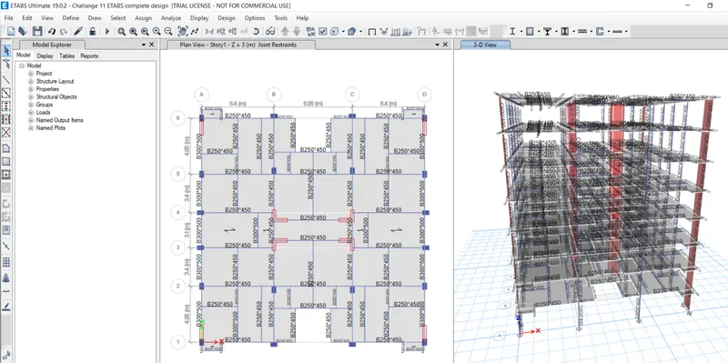
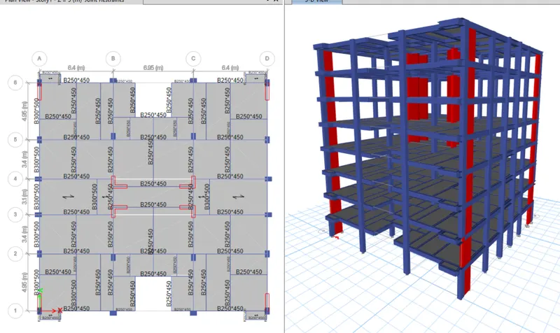
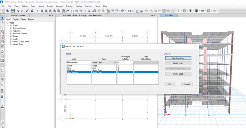
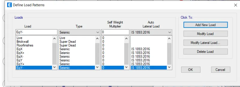
STEP 7: Defining Load Patterns
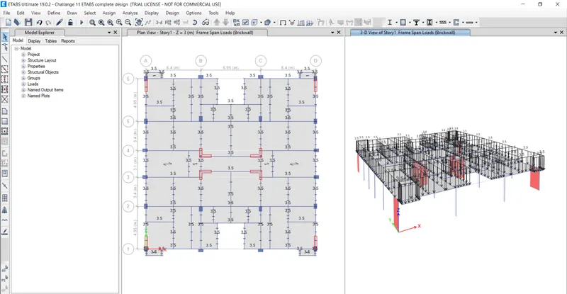
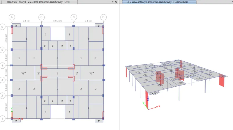
STEP 8: Assinging Loads Live load, Brick wall,Floor finish
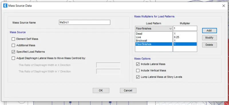
STEP 9: Providing the Mass source
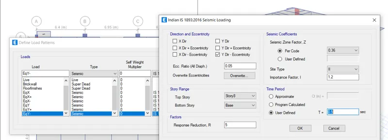
STEP 10: Defining Earthquake loads
Ta = (0.09*24)/squareroot of d = 4.5 seconds in both x and Y directions
STEP 11: Assigning Diaphragm
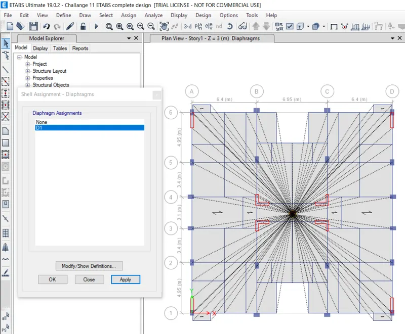
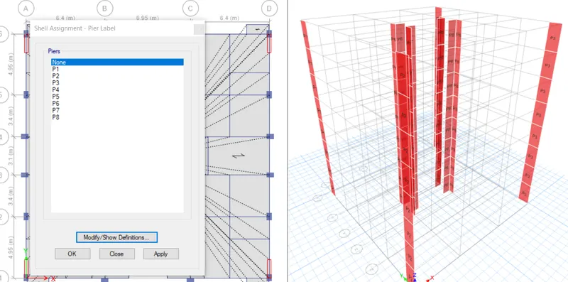
STEP 12: Giving PIER LABELS
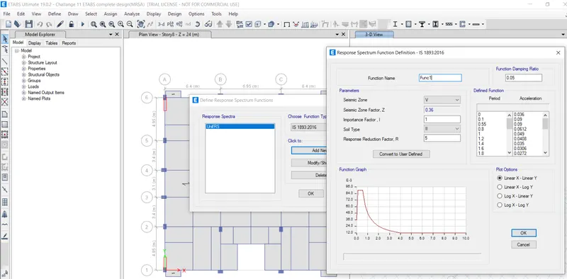
STEP 13: Defining Response Spectrum Analysis
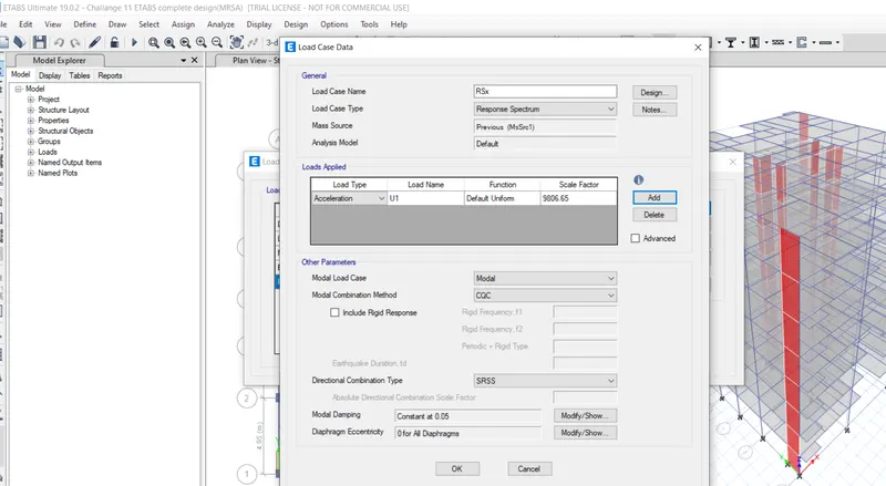
STEP 14:
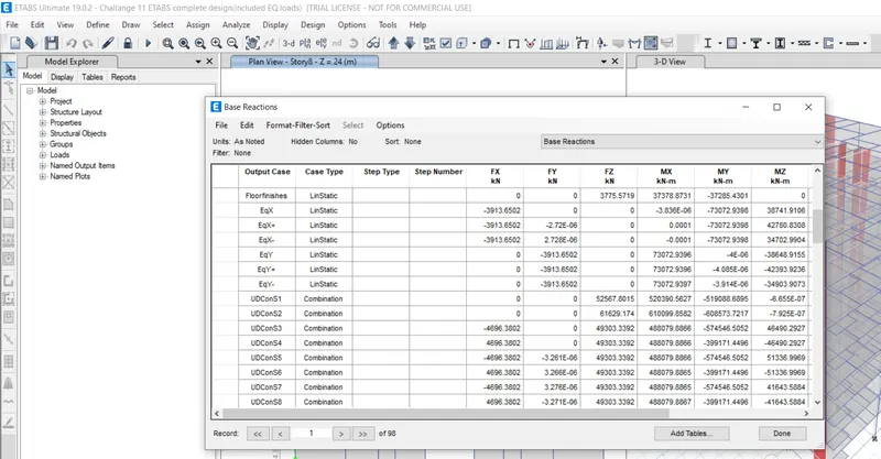
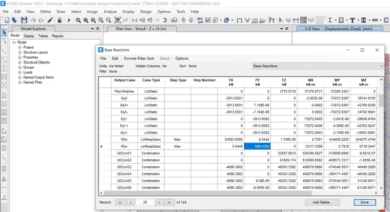
Comparision of BASE REACTIONS using Equvivalent Lateral force method vs Modal Response Spectrum Analysis
Base shear for Eqx and Eq y is 3913.65KN
For MRSA to get Scale factor = 3913.65/24583 = 0.16
For MRSA to get Scale factor = 3913.65/680 = 5.75
Eqx,Eqy values should be approximately equal to RSx ,RSy
STEP 15 : Obtaining the same values for both as per step 14
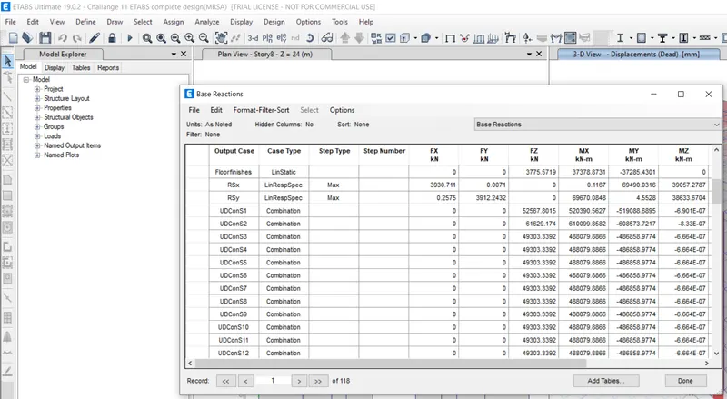
This Analysis is RUN only after deleting the EQx and EQy.
Obtained approx values for RSx and RSy in comparision with EQx and EQy
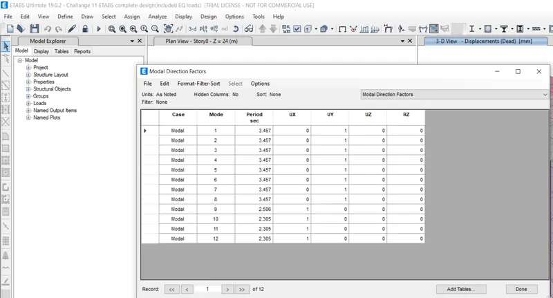
STEP 16: Fundamental Time period of the modes is checked for the modes
No proper result for any type of load combinations for UX and UY
Using MRSA No proper result
Using EQ loads No proper result for UX and UY
Using Gravity loads No proper result for UX and UY
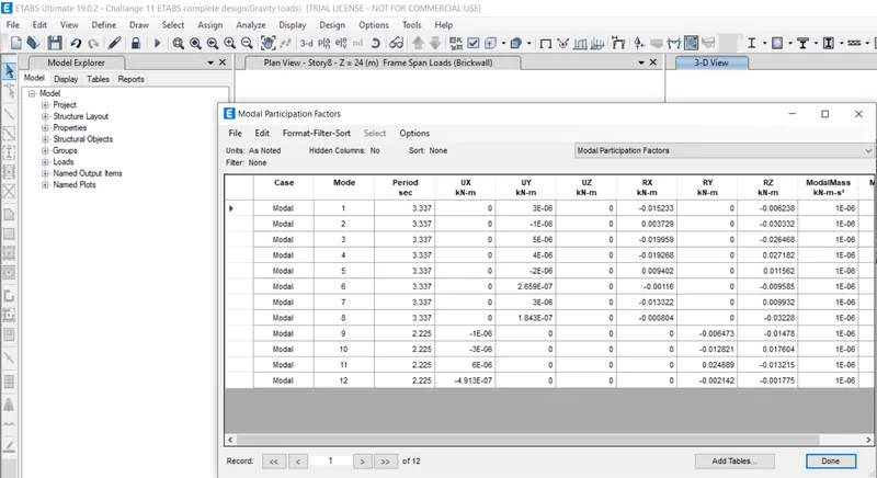
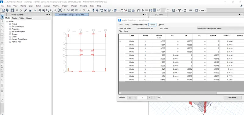
No proper result even after the analysis is obtained by using gravity loads (that is only DL,LL,Brick wall,Floor finish) + EQ loads in X and Y direction and the Beam at the opening between GRID B and C
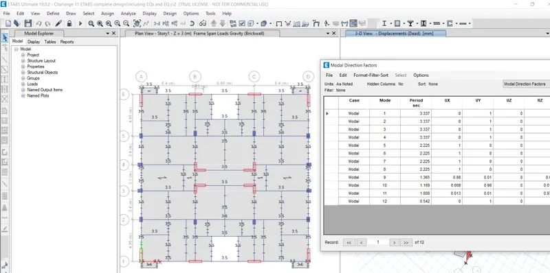
other analysis is also done without Beam between GRID B and C
But still the value is same
also there is no proper modal participating mass ratios
In UX,UY direcctions in both the cases.
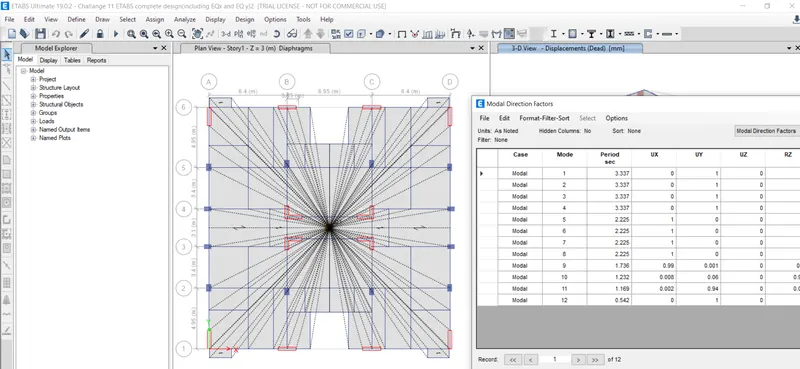
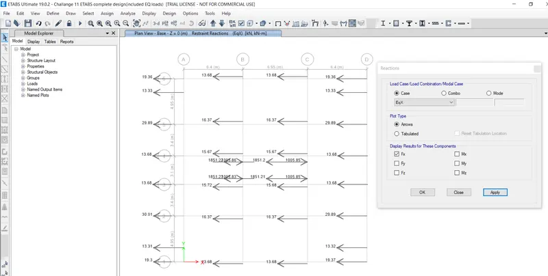
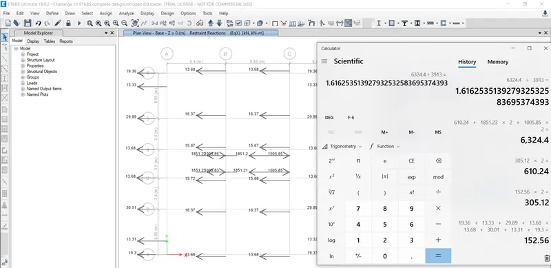
STEP 17: Check the BASE SHEAR for the EQx to make a way such that the total Lateral force in X direction is taken by the Shear walls is 75 to 80%
Here I got approx 61%
therefore the resizing of the model to be done for the Analyis of Building
That is the sizes of the Shear walls need to be increased.
SEE THE CALCULATION BELOW in calculator
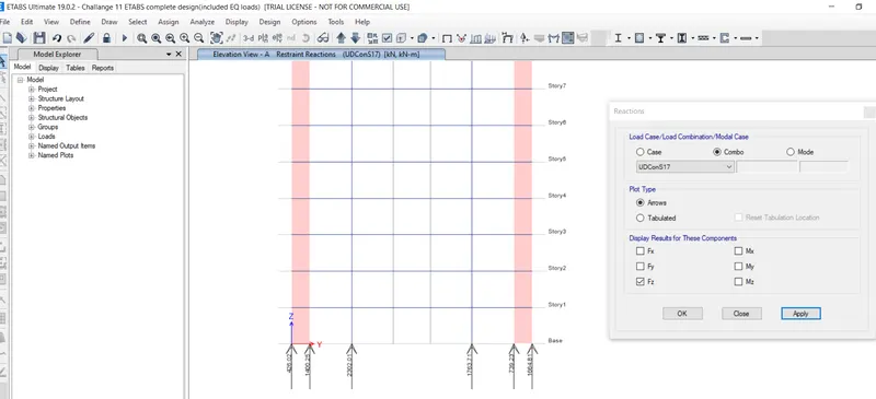
Use Fx here
STEP 18: Check for Axial load Ratio for columns it should not be greater than 0.4
For columns
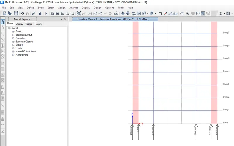
For Load combination 27 to 38 we have 0.9 DL
Therefore these load combinations are taken into account for the calculation of axial load ratio
The maximum load in a particular selected combination is taken and calculated for Axial load ratio
2741*1000/400/600/30=0.38 (approx to 0.4)
So it is almost good axial load ratio
Use Fz here
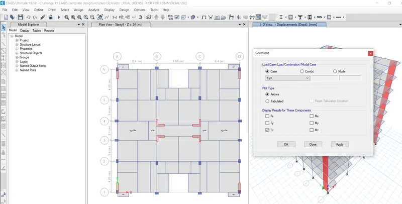
STEP 19: Check for Axial load Ratio for Shear walls it should not be greater than 0.28
For shear walls
For Load combination 15 to 26 we have 1.5 DL + 1.5 LL
Therefore these load combinations are taken into account for the calculation of axial load ratio
The maximum load in a particular selected combination is taken and calculated for Axial load ratio
2302*1000/400/600/30=0.32 > 0.28
So it is good axial load ratio
Use Fz here