Week 9 Challenge
- Generate seismic loading based IS codal provisions and zone II. Any other data you can assume and input accordingly
Answer:
Criteria for Earthquake Resistant Design of Structures is the Code IS 1893-2016 (Part-1) used for the Generation of the Seismic loading.
The Code Provides all the Design requirements for the Steel and Concrete Buildings for Earthquake Resistant Design of the Structure.
For the loading of the seismic force we have to consider some Basic Information and Pre-requisites for the Earthquake Respones of the Building.
It may include:
1.Type of the Structure
2.Type of the Soil
3.Zone in which the Building is located
4.Type of method used for Analysis
5.Irregularities in Plan
6.Irregularities in Elevation
7.No of storeys in the Building
8.Importance of the Structure
9.Resisting System used for Seismic Force (MRF or Shear wall or Dual)
Step 1:
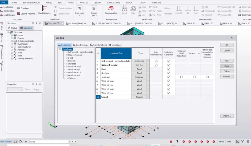
Add Load cases for Seismic loading
Step 2:
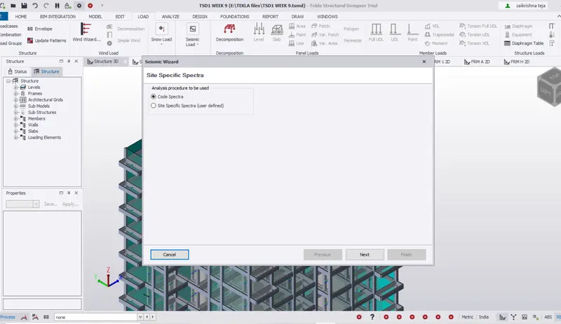
Go to load > Seismic Load > Seismic Wizard
Step 3:
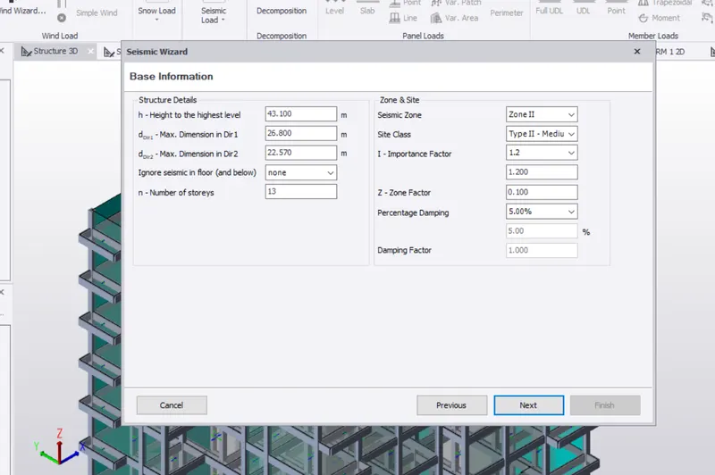
Enter the Basic Information
Seismic Zone II
Importance Factor = 1.2 From Clause 7.2 of IS 1893
Zone Factor = 0.1 From Table 2 IS 1893
Damping Percentage = 5% Clause 7.8 Table 3 IS 1893
Step 4:
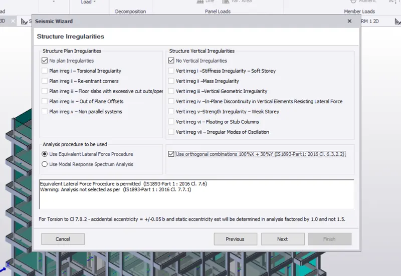
Irregularities in Plan and Elevation Clause 7.1 IS 1893
Step 5:
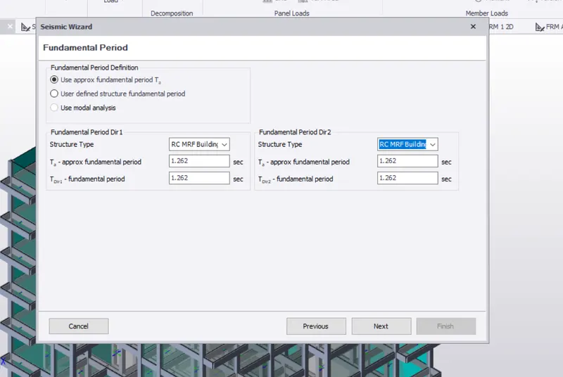
Equivalent Lateral Force Method is choosen
Fundamental period Clause 7.6 IS 1893
Step 6:
Select the Seismic Force Resisting System

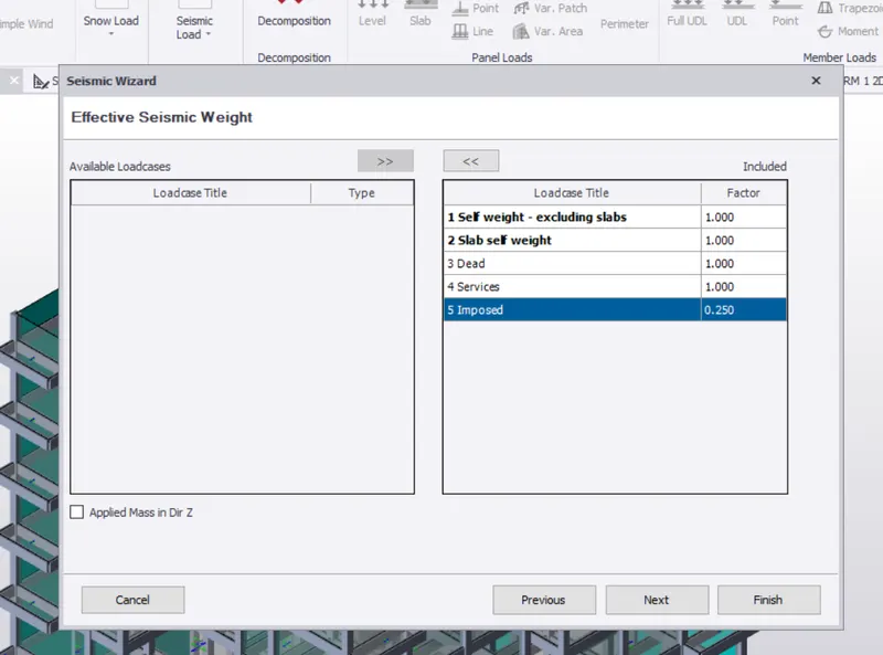
Step 7:
Add the load cases
Step 8:
Generate the load combination
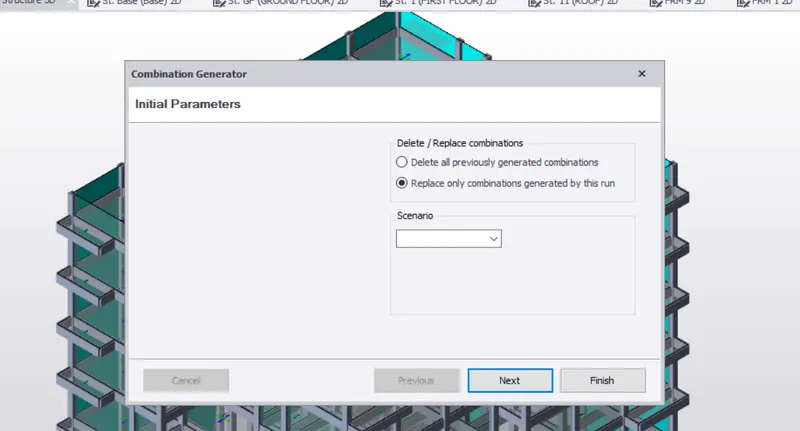
Step 9:
Check the Load combinations
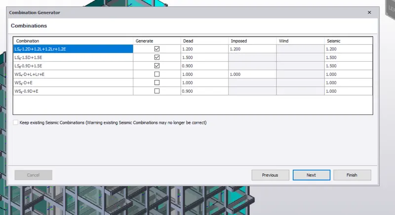
Load combinations for Service
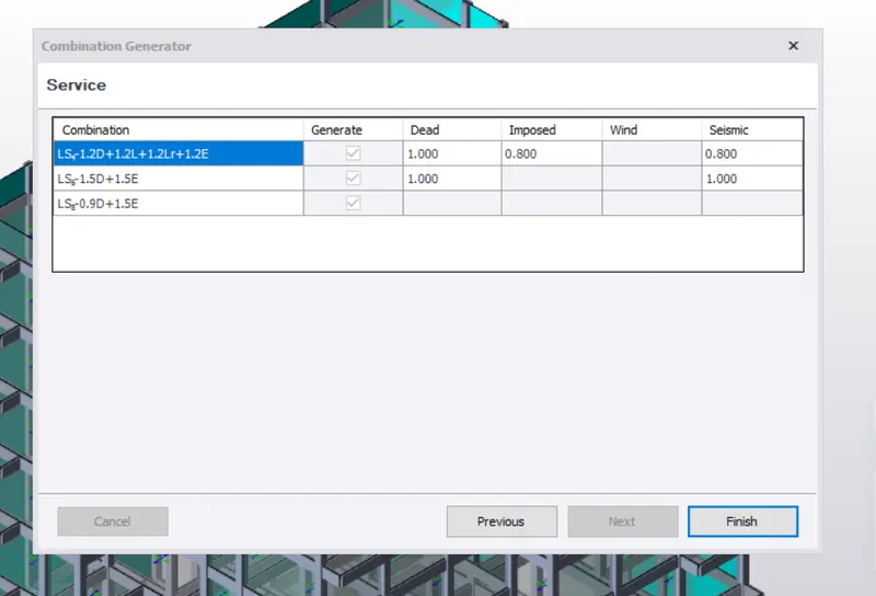
Finish the Seismic Load Application.
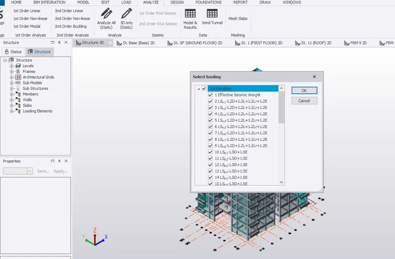
Now Analyse the Structure with the Given Combinations
Go to Analyze> Select the load combiantions
Now RUN the Analysis
Do 1st order Linear Analysis for the Structure.
Check the Results.
2.Run the analysis. Summarize your understanding of the analysis results
Answer:
Now after the RUN
Check for the Results in Result Mode
Go to Result
Check for the Moment in Major axis
Check for Moment in Minor axis
Check for Shear in Major axis
Check for Shear in Minor axis
Check for Axial Forces
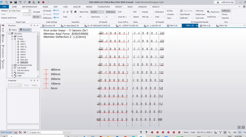
Check for Deflection values in X , Y , Z Directions
The values are to be in the limit for the success of the structure with all the members to be passed.
All the above values are to be checked for Different Load Combinations for Different type of members for the Frames and Floors.
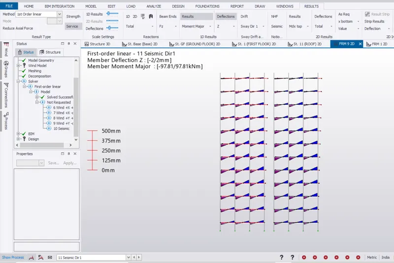
For Frame 9 = Face A
Apply seismic force in Direction 1
Check for the Moment in Major axis
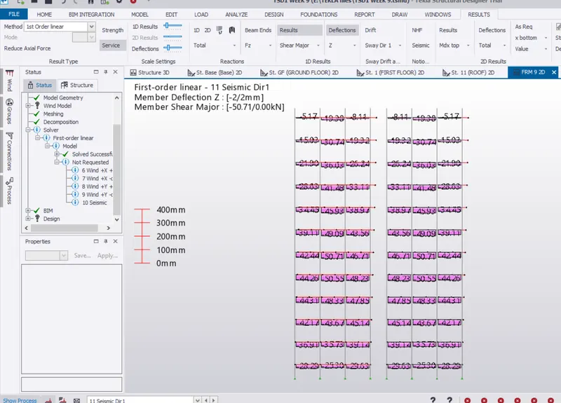
For Frame 9 = Face A
Apply seismic force in Direction 1
Check for Shear in Major axis
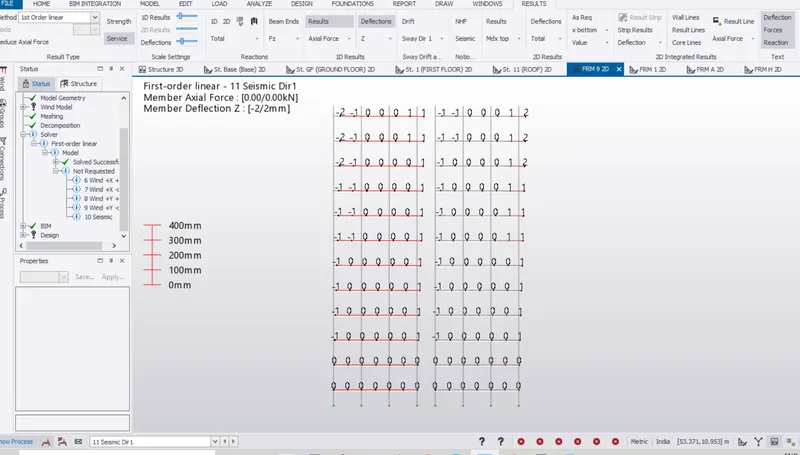
For Frame 9 = Face A
Apply seismic force in Direction 1
Check for Deflection values in Z Direction
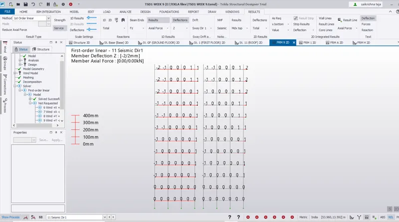
For Frame 9 = Face A
Apply seismic force in Direction 1
Check for Axial Forces with Deflection
For Frame 1 = Face B
Apply seismic force in Direction 1
Check for the Moment in Major axis
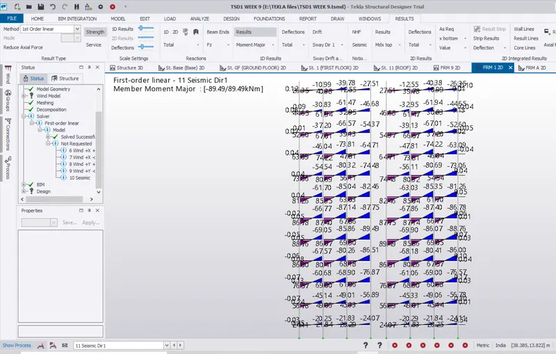
For Frame 1 = Face B
Apply seismic force in Direction 1
Check for Shear in Major axis
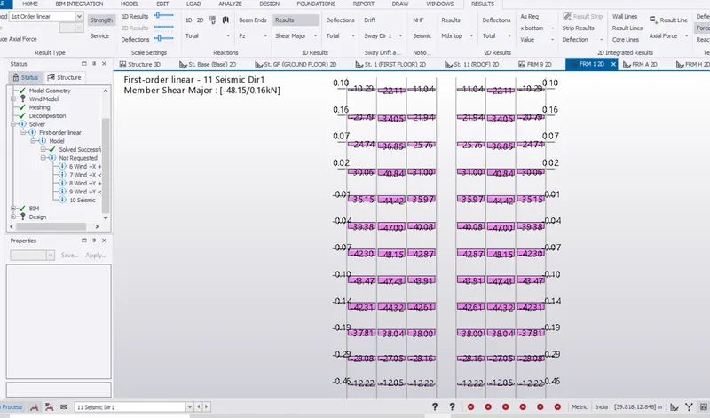
For Frame 1 = Face B
Apply seismic force in Direction 1
Check for Deflection values in X Direction
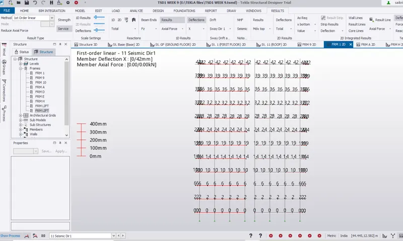
For Frame 1 = Face B
Apply seismic force in Direction 1
Check for Deflection values in Y Direction
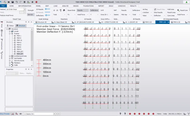
For Frame 1 = Face B
Apply seismic force in Direction 1
Check for Deflection values in Z Direction
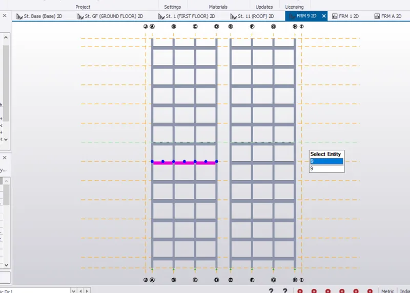
The Analysis for the Beam can also be done for a Particular Beam or column
whether the Beam is continuous or Cantilever or Simply supported
Here a Beam which is continuous is selected from the Fifth Floor in Frame 9 = face A
The analysis is done in the below figure
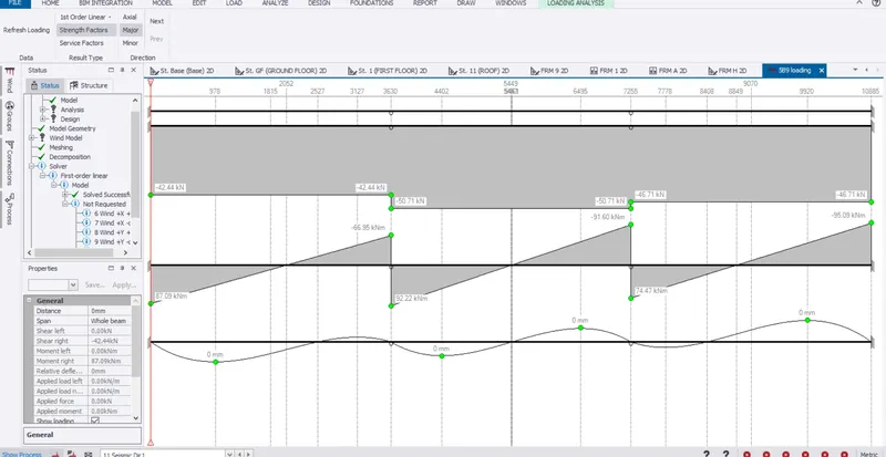
The analysis for the Continuous Beam is made by
Select the Beam > Right click > Open Load Analysis view
This type of loading can be for different load combinations.
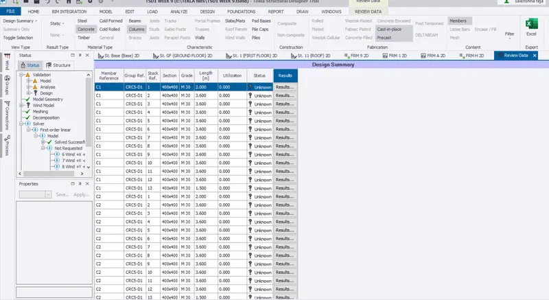
The Review data for the Members can be extracted from the Review view
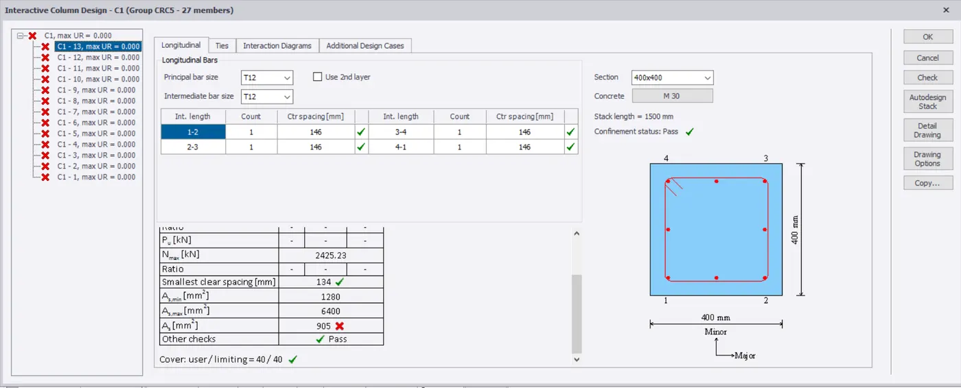
It is helpful for the Designer to check whether the member is passed or not.
The Review Tabular form helps in checking
1.Design summary
2.Sway
3.Inter story shear
4.Cumulative story shear
5.seismic drift
6.Wind drift
7.Connection resistance
8.Material list
9.Floored Area