Project 2
Project 2:
Aim:
To Develop general arrangement for the RC office building. Analyze and design the building as per IS standard code in TEKLA STRUCTURAL DESIGNER. Refer the attached plan and elevation. The building to be designed for dead, live, wind and seismic loading.
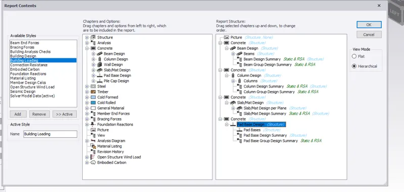
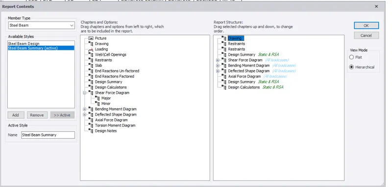
Report of each member to be generated and extract drawings for structural plans, beam reinforcement details from the software
Procedure:
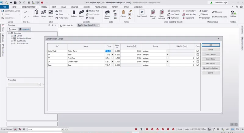
1.Construction levels are created as per the Given Elevation View
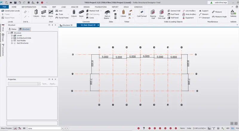
2.Grids Lines are generated as per the Plan View
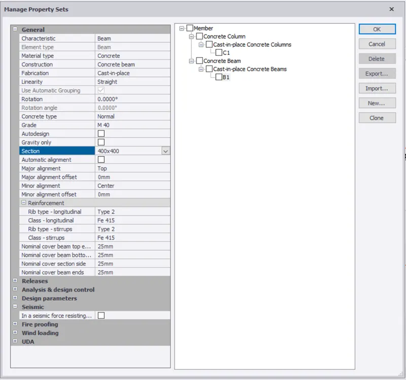
3.Create Property sets for the Column C1 ,Beam B1
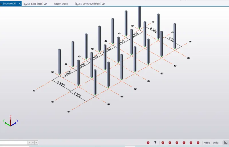
4.Columns of size 600*600 is created from Base to Roof level
Apply the Properties of the Member after assigning them to the Respective Positions
5.Beams of Size 400*400 are created in the Ground Floor asper the Given plan
Apply the Properties of the Member after assigning them to the Respective Positions
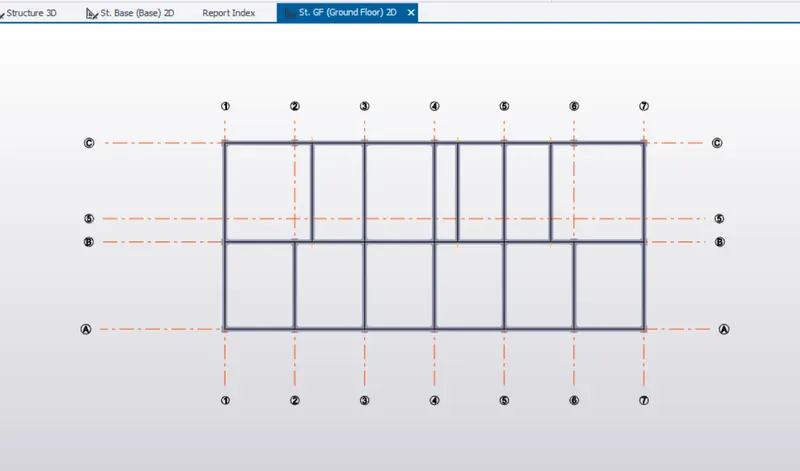
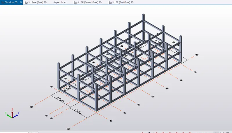
6.The Beams drawn for the First Floor and the Roof as well
The Size of the Beam is 400mm*400mm B1
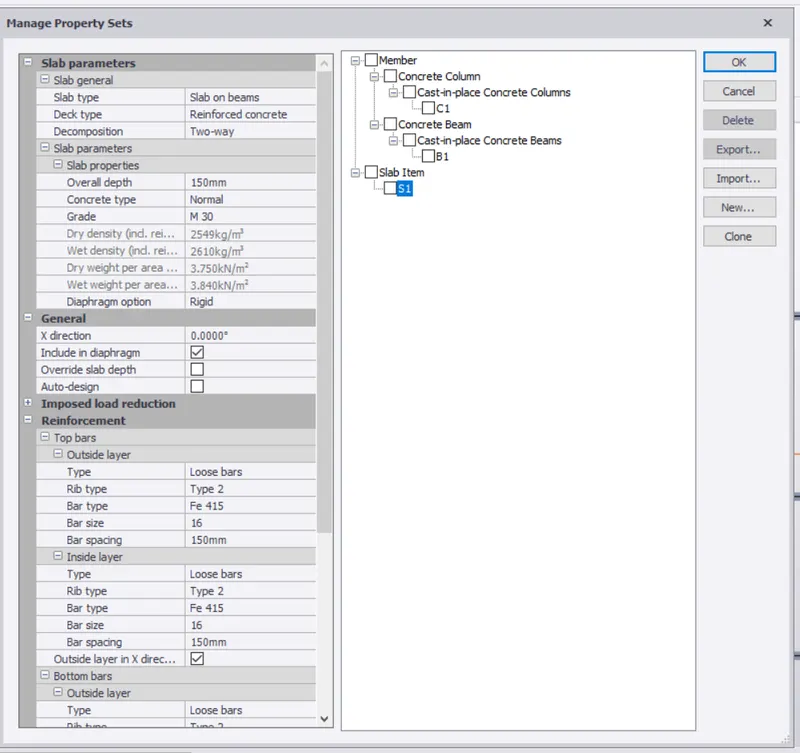
7.Now To draw the slab the properties are created as S1
Slab on Beams, Two way slab
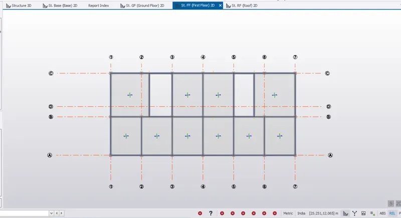
8.Apply the Properties of the slab S1
Slabs are assigned for
Ground Floor
First Floor
Roof
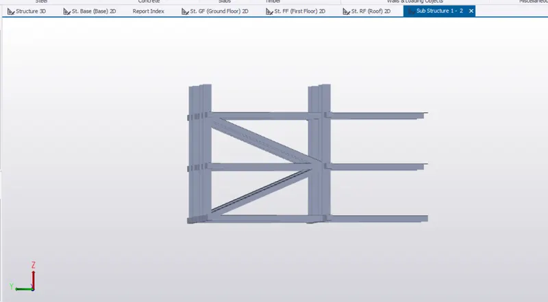
9.To draw stair case Beam
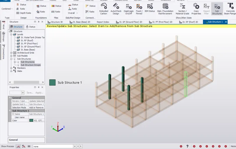
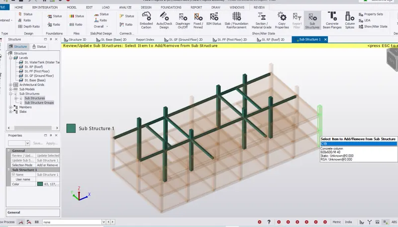
First the Beams and Columns are added to the Substructure as shown below
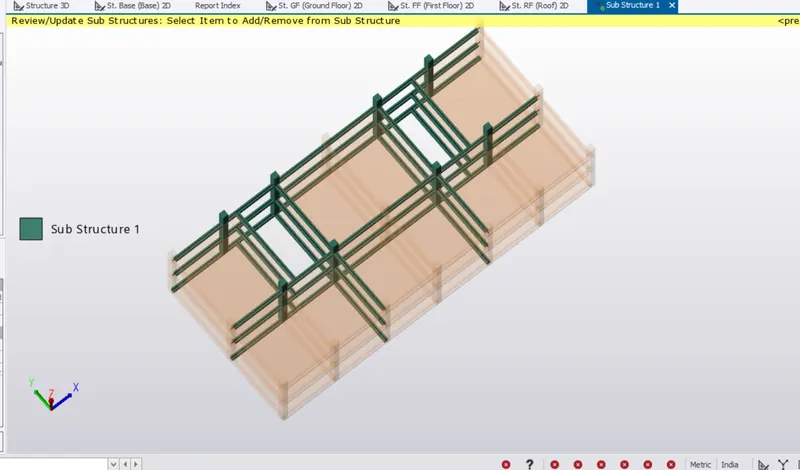
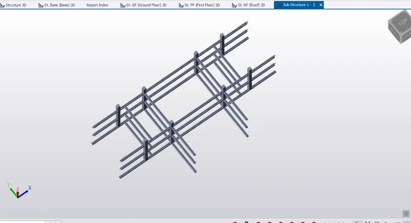
10.The View of Beams and columns which are added in the Sub structure
11.Now sloped Beams are Drawn for connecting the added Beams and columns
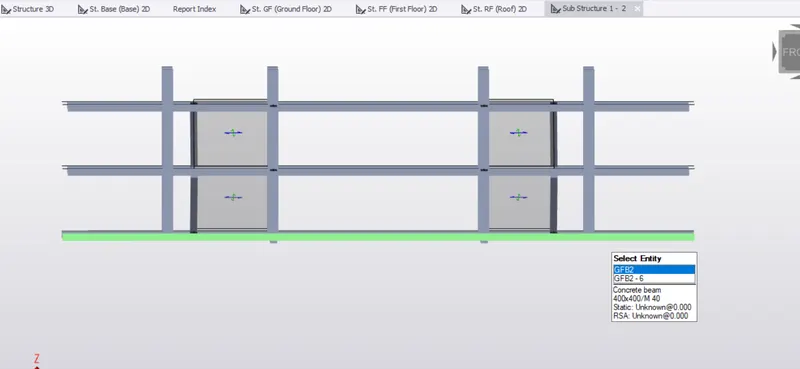
12.To Apply the Stair case Slab
For the properties of the Stair case the Slab on Beams the Diaphragm to be added is unchecked
Later add the Slabs to the Stair case
Details of the Structure:
Support = Fixed-Fixed (Top and Bottom)(Mx and My will be formed)
Conrete used M40
Concrete Column Size C1 = 600mm*600mm
Concrete Beam Size B1 = 400mm*400mm
B2 :300*600
B3 :350*700
Slab Items for both S1 and S2
Concrete grade M 30
Overall depth =150
Loadings:
The building to be designed for dead, live, wind and seismic loading.
Loads Calculation:
Unit weight of concrete = 24KN/m3
1.Dead Load:
1.Finishes Loading = 0.05*24 = 1.2 KN/m2 (Area Loading)
2.Slab load will be Designed by Software
3.Brickwall Loading
Thickness of Brickwall = 150 mm
Unit weight = 20KN/m3
Floor Height = From Ground Floor to First Floor = 3.7m
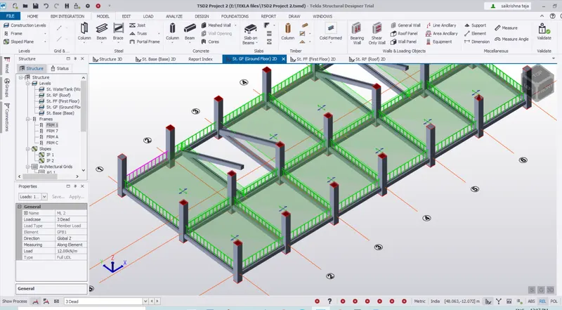
Brickwall loading = 0.15*20*3.7 = 12 KN/m
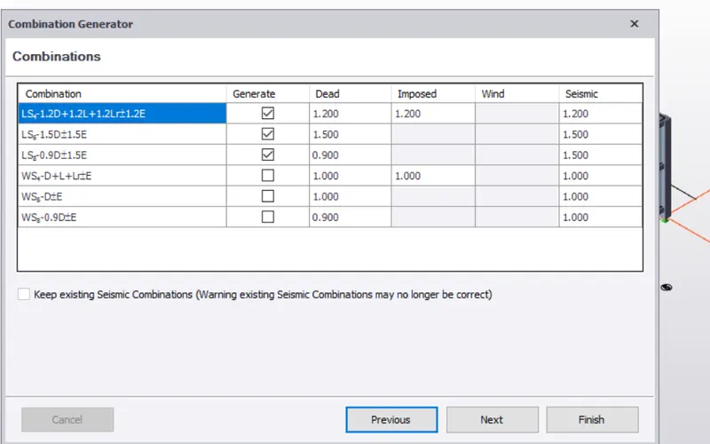
Load combinations are Generated
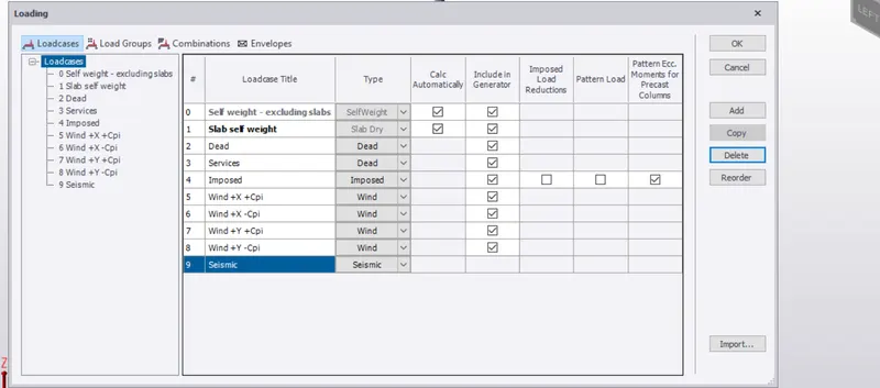
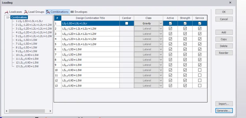
Dead load =1.2 KN/m is applied on the Slabs
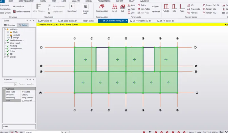
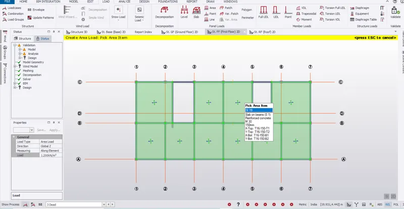
Dead load of 12 KN/m is applied on the Beams of Ground Floor,First Floor
2.Imposed Load:
Ground Floor Rooms:
Office = 3KN/m2
Stair case = 5KN/m2
Pantry =3 KN/m2
Conference Room = 5KN/m2
Control Room = 5KN/m2
Lobby = 5 KN/m2
Toilet = 2KN/m2
M&E Room = 5 KN/m2
First Floor Rooms:
Staircase = 5KN/m2
Office =3 KN/m2
Toilet = 2KN/m2
Lab = 3 KN/m2
Conference Room = 5KN/m2
Pantry =3 KN/m2
M&E Room = 5 KN/m2
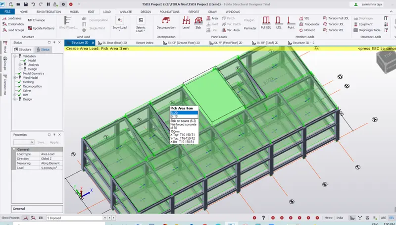
3.Wind load
For Application of wind Loading
First Create Wall Panels and Roof Panels
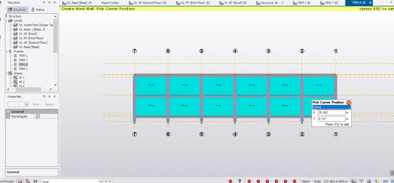
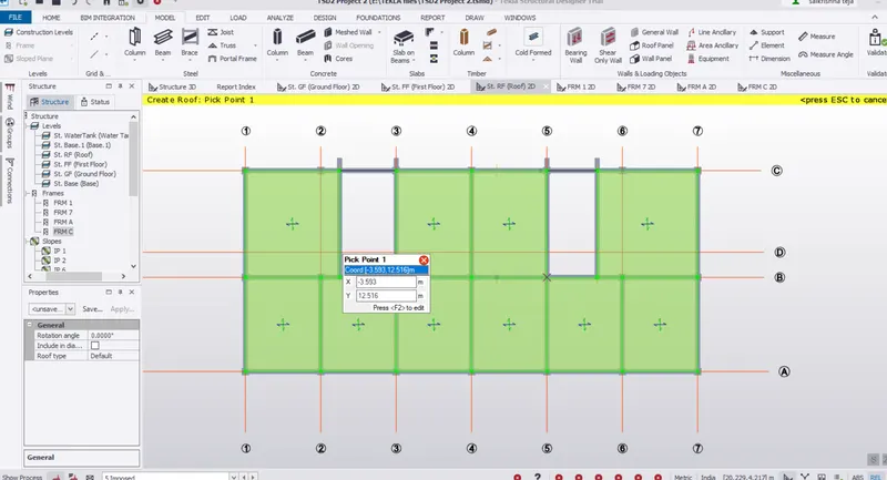
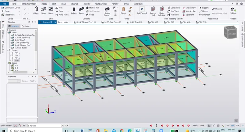
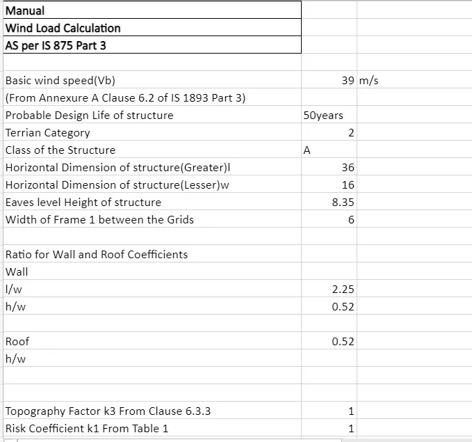
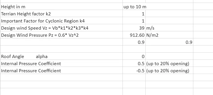
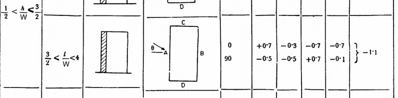
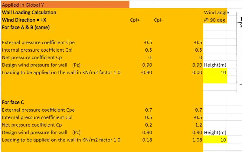
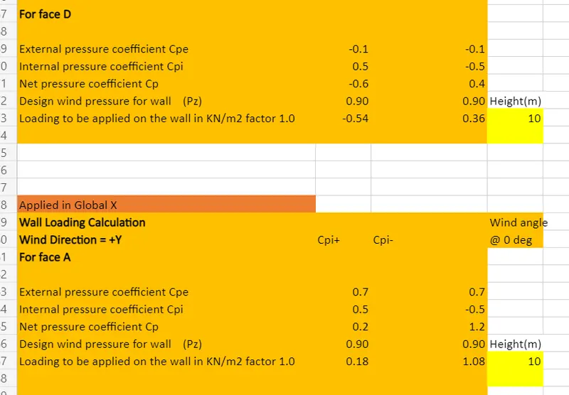
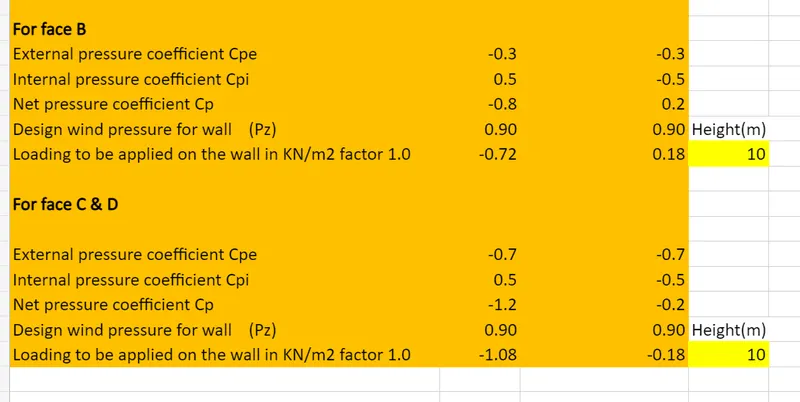
For Face A and Face B apply in Global Y
For Face C and Face D apply in Global X
Wind Load is applied as PATCH load only
Now for Wind +X +Cpi
Wind load is applied
Face A = Frame 9
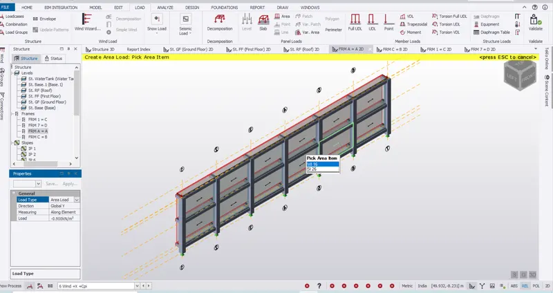
Wind +X +Cpi
Wind load is applied
Face B = Frame 1
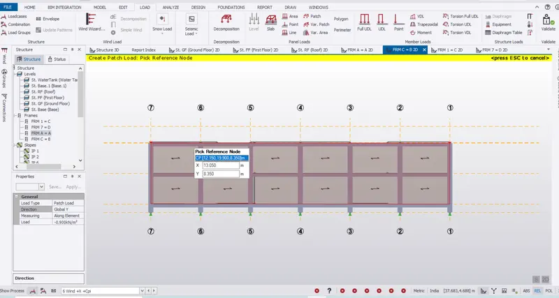
Wind +X +Cpi
Wind load is applied
Face C = Frame A
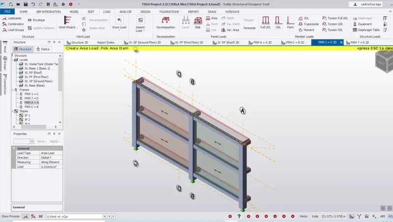
Wind +X +Cpi
Wind load is applied
Face D = Frame H
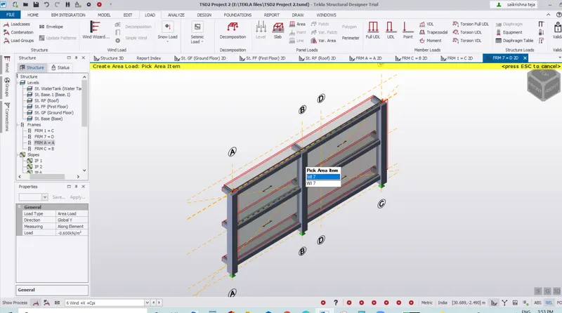
Simillarly we Apply
Wind +X -Cpi
Wind -X +Cpi
Wind -X -Cpi
Wind +Y +Cpi
Wind +Y -Cpi
Wind -Y +Cpi
Wind -Y -Cpi
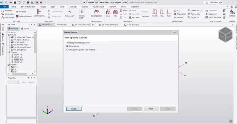
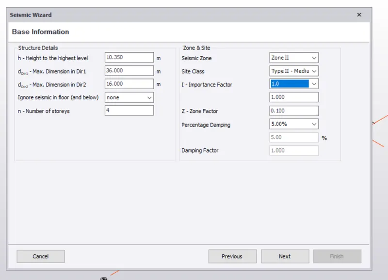
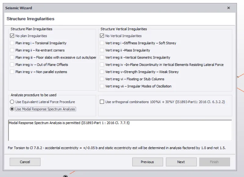
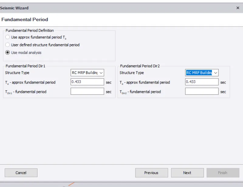
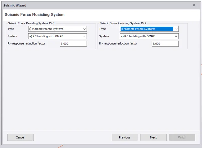
4.Seismic Load
Design of Members:
Columns:
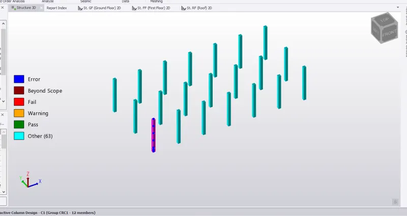
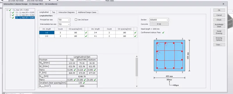
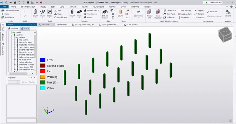
All Columns are passed
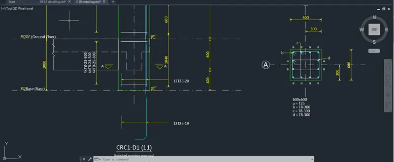
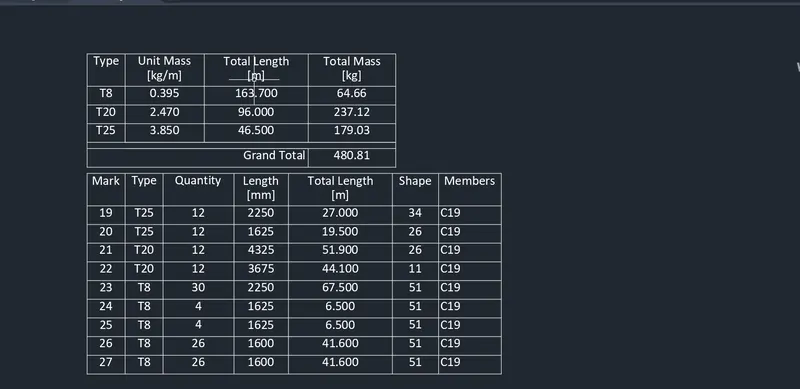
AutoCad Drawing detailing of Columns
Schedule of column
Beams Design:
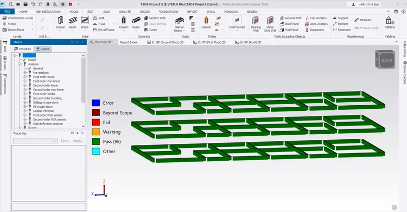
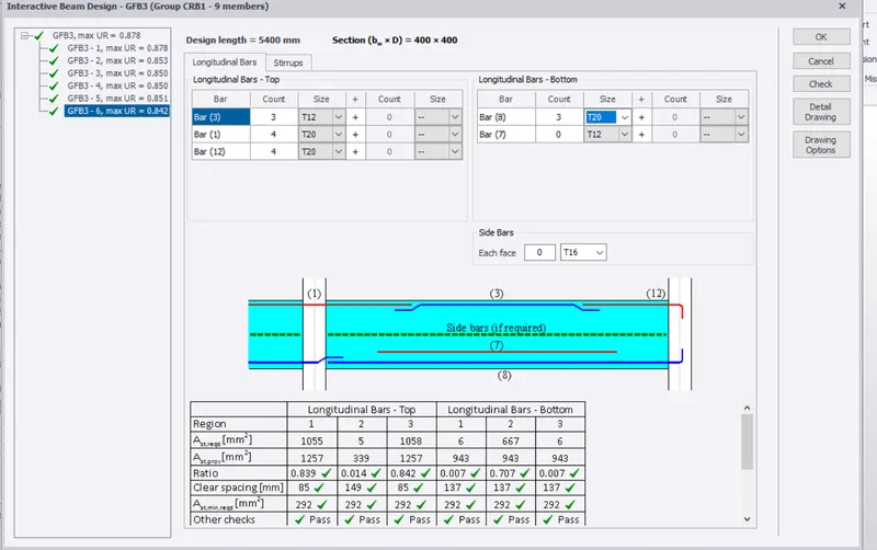
All Beams are Passed
Autocad drawing Detailing of Beam
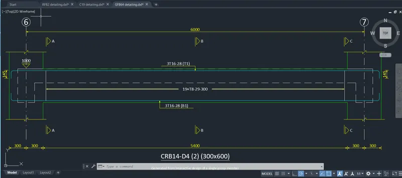
Detailing of Beam
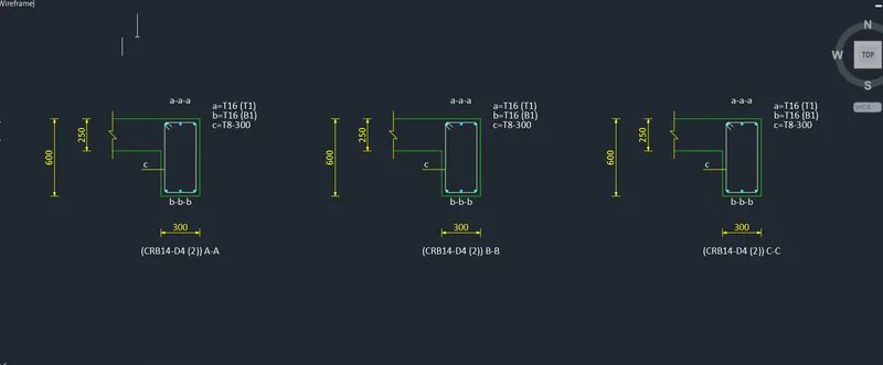
Schedule of Beams
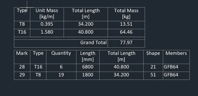
Slabs:
All slabs are passed
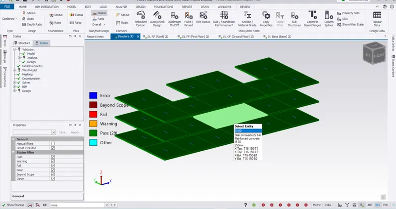
Slab Design Details
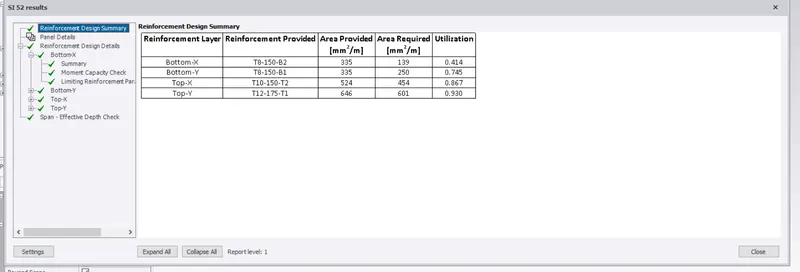
Foundations
Pad Foundations Isolated Footing is Provided
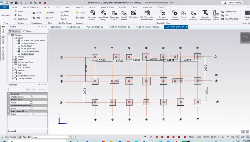
Isolated Footing Details
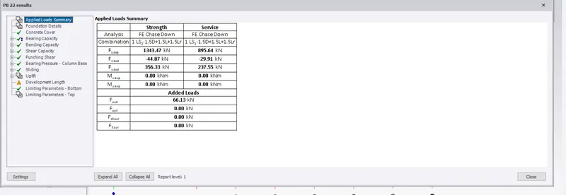
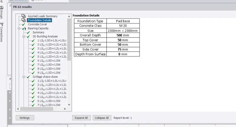
Foundation Summary and Design Details
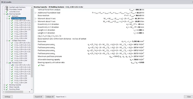
Drawing of Foundation
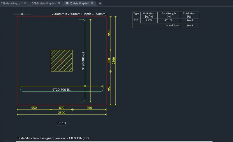
All foundations are Ok with small warning for Development Length
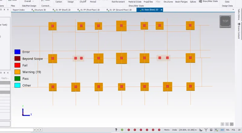
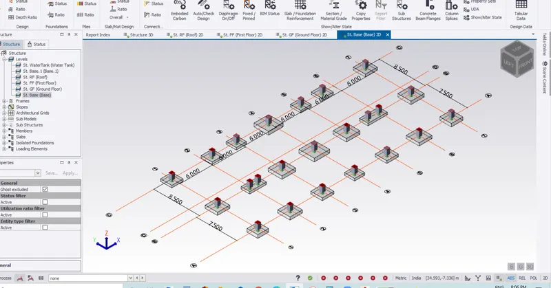
View of Foundations in 3D
Result:
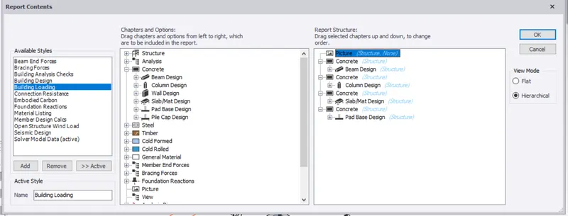
Report Generation
Report for Beam Design,Column Design,Slab or Mat Design , Pad Base Design
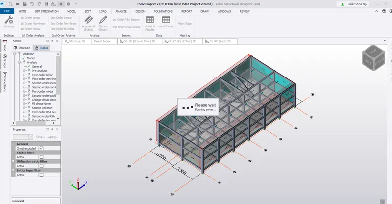
Analysis