Reinforcement Detailing of Beams from ETABS output
Question:
Detail design of beams in Etabs 2018.
The ETABS file for a G+4 building is provided. Run the analysis and design the RCC Moment ResistingFrame. The following challenge deals specifically with two continuous beams in the 1st floor.
1) 3 span continuous beam along grid A
2) 7 span continuous beam along grid 3
Address the following issues thereafter.
• Provide details of longitudinal and shear reinforcement for the two continuous beams.
Answer:
Run the Analysis for the given structure.
The Design for the steel reinforcement is carried out to get the results for the Beams.
For getting the results click on "Concrete Frame Design".
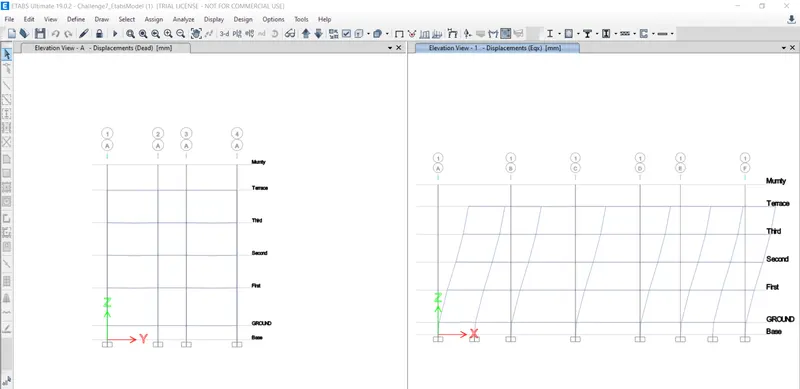
For the 3 span continuous beam along grid A
Here is the Table for the Beam with longitudinal reinforcement and shear reinforcement along the Grid 3. Beam size = 300mm*500mm
| S.No | First floor elevation in m | Beam length in m | Beam number | Load Combination | Combination due to | Max longitudinal reinforcement at |
Equivalent Shear Force (Gravity+Capacity)in KN |
Max shear reinforcement at in cm2/m |
| 1 | 5.5 | 5.375 | 38 | UDcon66 | 1.5D.L + 1.5 Brick wall + 1.5 Floor finish + 1.5 EqY(-) | 5.050m (1906mm2,953mm2) | 242.75 | 15.12 |
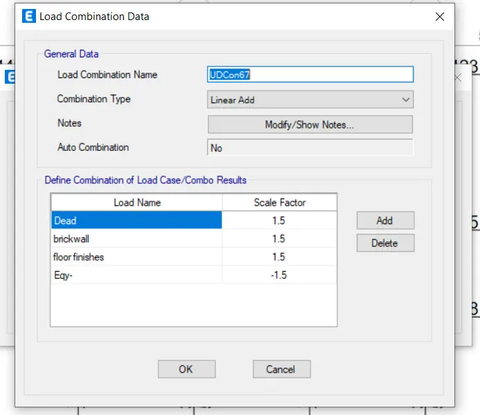
| 2 | 5.5 | 3 | 34 | UDcon67 | 1.5D.L + 1.5 Brick wall + 1.5 Floor finish - 1.5 EqY(-) | 0.325m (2045mm2,1022mm2) | 414.58 | O/S #45 (BEAM FAILED) |
| 3 | 5.5 | 5.375 | 33 | UDcon67 | 1.5D.L + 1.5 Brick wall + 1.5 Floor finish - 1.5 EqY(-) | 0.325m(1896mm2,948mm2) | 237.54 | 14.79 |
For the 7 span continuous beam along grid 3
Here is the Table for the Beam with longitudinal reinforcement and shear reinforcement along the Grid 3. Beam size = 300mm*500mm
| S.No | First floor elevation in m | Beam length in m | Beam number | Load Combination | Combination due to | Max longitudinal reinforcement at | Equivalent Shear Force (Gravity+Capacity)in KN | Max shear reinforcement at in cm2/m |
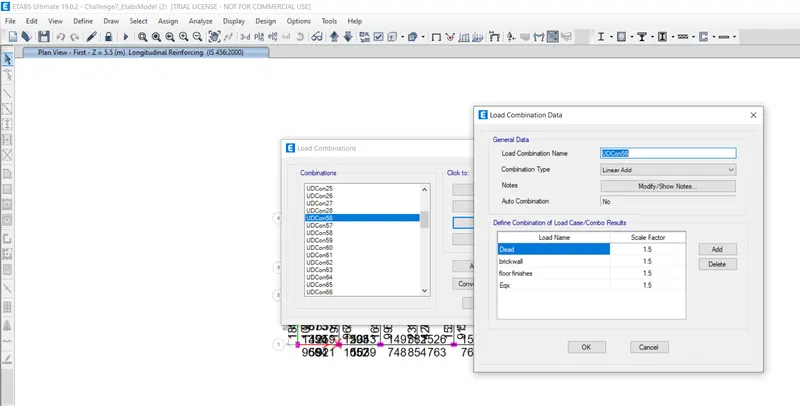
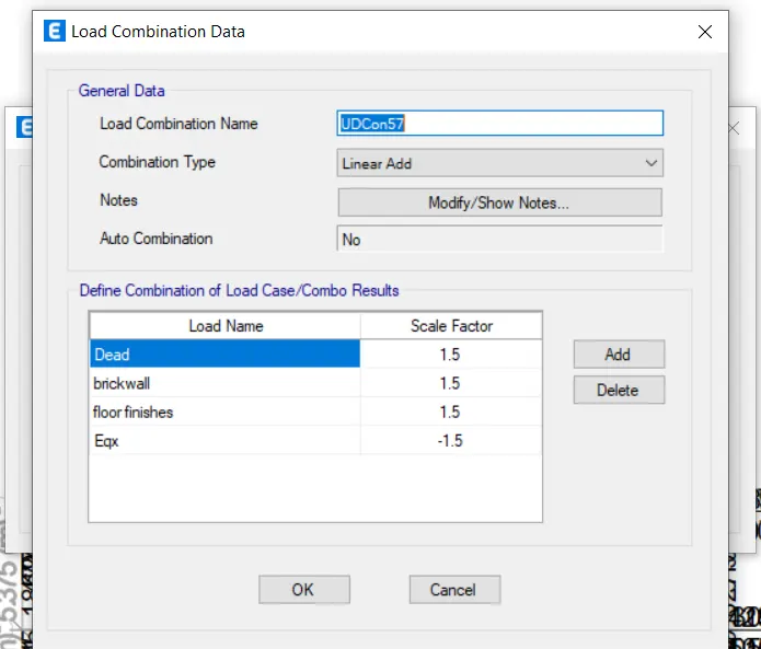
| 1 | 5.5 | 4.5 | 24 | UDcon57 | 1.5D.L + 1.5 Brick wall + 1.5 Floor finish - 1.5 EqX | 0.225m (1408mm2,704mm2) | 209.58 | 13.05 |
| 2 | 5.5 | 4.5 | 25 | UDcon56 | 1.5D.L + 1.5 Brick wall + 1.5 Floor finish + 1.5 EqX | 4.175m (1308mm2,654mm2) | 193.55 | 12.05 |
| 3 | 5.5 | 8 | 69 | UDcon56 | 1.5D.L + 1.5 Brick wall + 1.5 Floor finish + 1.5 EqX | 7.6750m(1938mm2,969mm2) | 232.00 | 14.45 |
| 4 | 5.5 | 8 | 70 | UDcon57 | 1.5D.L + 1.5 Brick wall + 1.5 Floor finish - 1.5 EqX | 0.3250m(1940mm2,970mm2) | 232.09 | 14.45 |
| 5 | 5.5 | 5 | 73 | UDcon57 | 1.5D.L + 1.5 Brick wall + 1.5 Floor finish - 1.5 EqX | 0.3250m(1425mm2,713mm2) | 219.45 | 13.67 |
| 6 | 5.5 | 4 | 14 | UDcon57 | 1.5D.L + 1.5 Brick wall + 1.5 Floor finish - 1.5 EqX | 0.3250m(1301mm2,650mm2) | 211.14 | 13.15 |
| 7 | 5.5 | 4 | 16 | UDcon56 | 1.5D.L + 1.5 Brick wall + 1.5 Floor finish + 1.5 EqX | 3.7750m(1367mm2,684mm2) | 210.00 | 13.08 |
Question:
Provide reasons for failure of the middle span along grid A. What are the possible ways this issue can be resolved?
Answer:
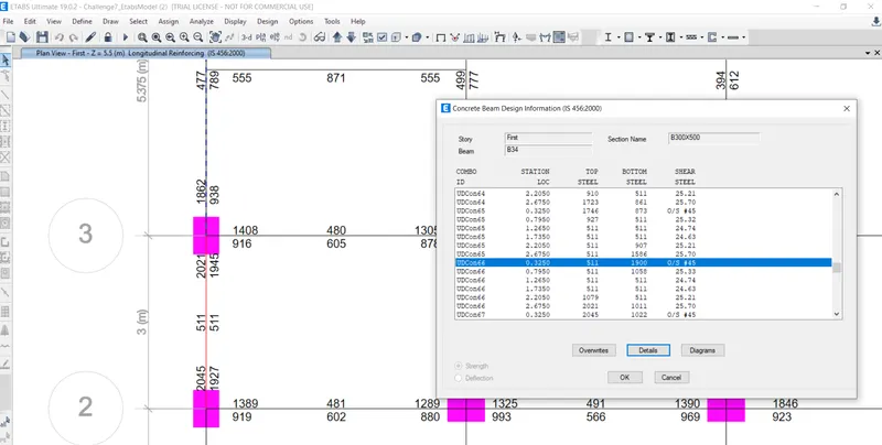
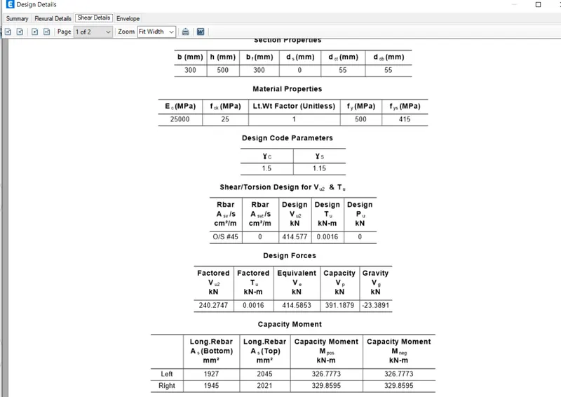
The Beam failed due to very high shear force of 414.58 KN which results in Failure of the Beam in shear before the Beam fails in the Flexure.
To tolerate the High shear reinforcement provide Diagonal Bars for the Beam.
Question:
Calculate value of the maximum shear force in any one of the spans in both the continuous beams, as per clause 6.3.3 (b) in IS 13920 – 2016. Also, confirm these values from shear force demand calculated by ETABS.
Answer:
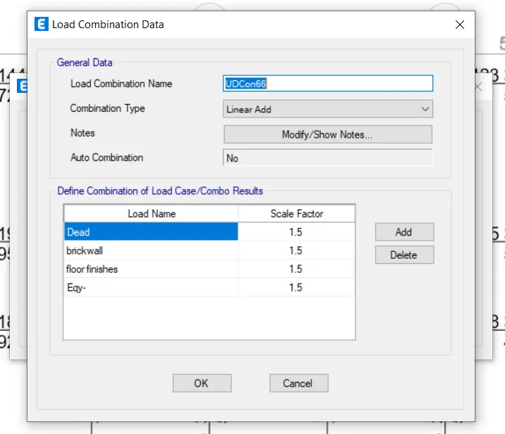
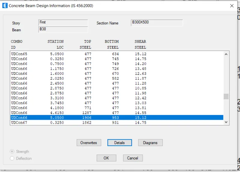
Considering the Beam no 38 along the Grid A with load combination UDcon66 the shear force demand and the shear reinforcement details as per ETABS is determined below;
(with the spacing required to be provided at different locations)
Span of the Beam = 5375mm
| S.No | Station Location in the beam | Steel reinforcement in cm2/m | Shear Demand as per ETABS in KN (Equivalent shear) |
| 1 | 0.325 | 14.75 | 236.83 |
| 2 | 0.750 | 14.20 | 227.95 |
| 3 | 1.175 | 13.48 | 216.47 |
| 4 | 1.600 | 12.63 | 202.76 |
| 5 | 2.025 | 11.87 | 190.66 |
| 6 | 2.450 | 11.28 | 181.17 |
| 7 | 2.875 | 10.85 | 174.29 |
| 8 | 2.875 | 11.98 | 192.41 |
| 9 | 3.310 | 12.42 | 199.49 |
| 10 | 3.745 | 13.03 | 209.30 |
| 11 | 4.180 | 13.81 | 221.79 |
| 12 | 4.615 | 14.55 | 233.64 |
| 13 | 5.050 | 15.12 | 242.75 |
From the Table we can observe that the Shear demand lowest is 174.29 KN and the highest is 242.75 KN
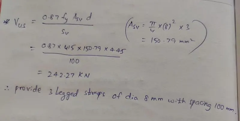
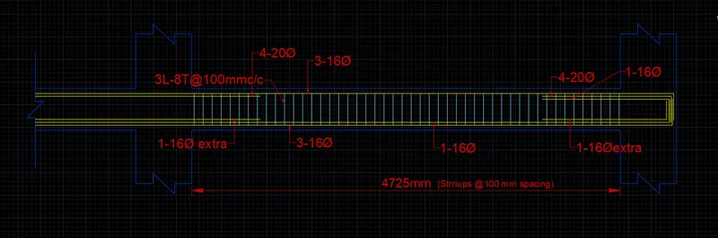
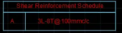
To get a uniform pattern provide 3Legged stirrups of diameter 8 mm with spacing 100mm along the whole span.
For Longitudinal reinforcement:
| Beam 38 | Left end | Center | Right end |
| Top reinforcement |
3-16 dia straight + 4-20 dia Steel Provided = 1862 mm2 |
3-16 dia straight Steel Provided = 477 mm2 (round to 603 mm2) |
3-16 dia straight + |
| Bottom reinforcement |
3-16 dia straight + 1-16 dia straight + 1-16 dia extra Steel Provided = 938 mm2 |
3-16 dia straight + 1-16 dia straight Steel Provided = 789 mm2 |
3-16 dia straight + 1-16 dia straight + 1-16 dia extra Steel Provided = 1020 mm2 |
Considering the Beam no 25 along the Grid 3 with load combination UDcon56 the shear force demand and the shear reinforcement details as per ETABS is determined below;
(with the spacing required to be provided at different locations)
Span of the Beam = 4500mm
| S.No | Station Location in the beam | Steel reinforcement in cm2/m | Shear Demand as per ETABS in KN (Equivalent shear) |
| 1 | 0.3250 | 11.77 | 189.033 |
| 2 | 0.8063 | 11.22 | 180.1203 |
| 3 | 1.2875 | 10.47 | 168.16 |
| 4 | 1.7688 | 9.55 | 153.41 |
| 5 | 2.2500 | 8.81 | 141.50 |
| 6 | 2.7313 | 9.83 | 157.93 |
| 7 | 3.2125 | 10.75 | 172.68 |
| 8 | 3.6938 | 11.50 | 184.63 |
| 9 | 4.1750 | 12.05 | 193.55 |
From the Table we can observe that the Shear demand lowest is 141.50 KN and the highest is 193.55 KN
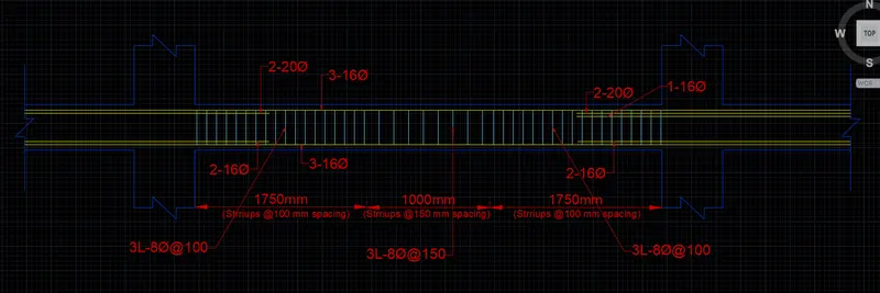
Arrange shear reinforcement as
- From 0 to 1750mm and 2750 mm to 4500mm which is greater than (2d=2*445=890mm) from the both the ends
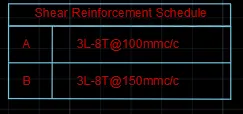
3Legged stirrups of diameter 8 mm with spacing 100mm and
- At the centre 1000mm provide
3Legged stirrups of diameter 8 mm with spacing 150mm
For Longitudinal reinforcement:
| Beam 25 | Left end | Center | Right end |
| Top reinforcement |
3-16 dia straight + 2-20 dia Steel Provided = 1237 mm2 |
3-16 dia straight Steel Provided = 476 mm2 (round to 603 mm2) |
3-16 dia straight + 2-20 dia + 1-16 mm dia extra Steel Provided = 1308 mm2 |
| Bottom reinforcement |
3-16 dia straight + 2-16 dia Steel Provided = 933 mm2 |
3-16 dia straight Steel Provided = 546 mm2 |
3-16 dia straight + 2-16 dia Steel Provided = 918 mm2 |