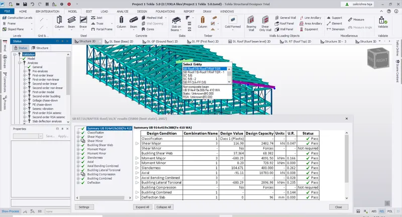
Project 1
Question:
Analyze and design a steel building to 10T CRANE as per IS standard code in TEKLA STRUCTURAL DESIGNER. Refer the attached plan and elevation. Provide bracings and moment connection for lateral stability.
Consider dead, live, equipment and wind loading. Consider the brick wall loading for 150mm thick and 1.5 KN per sq m for wall and roof cladding.
Assume wind loading basic speed as 39m/s
Report of each member to be generated and extract drawings of structural plans from the software
Answer:
AIM:
To Generate a Steel Structure with all the elements and loads and to check their Stability by Analysis and Design them using TEKLA tools
PROCEDURE:
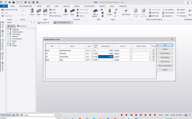
1.Creation of Construction Levels for the given model
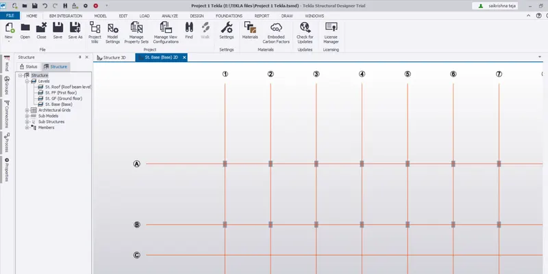
2.Creation of Grids on bothsides according to the Plan given in the Drawings
3.Creation of Member Properties for the Model
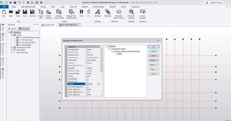
4.Apply the Properties of the Member after assigning them to the Respective Positions (Concrete Pedestal PD1)
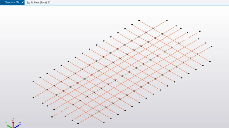
5.Steel Column Members created from Ground Floor to the Roof of Beam Level
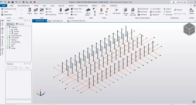
6.Steel Beams are Created and placed on their respective positions as per the Plan
Beams B1,B2,Rafter,Ridge
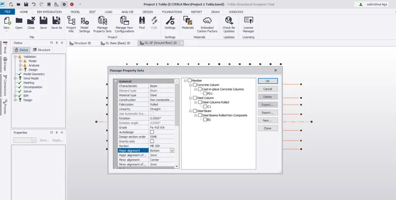
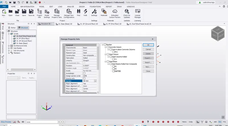
7.After Placing the Beams Rafters and Ridges then Bracings are created.
Type of Bracings created are
a.Horizontal Bracings
b.X Bracings
Horizontal Bracings are Provided to support the X bracings at the Mid span of the Rafters and Ridges
X Bracings connect the Rafters and the Ridges using the Horizontal Bracings.
Bracings are provided at:
a.Bracings are provided on the Roof of Beam level
b.Bracings are provided vertically in the Place of wall openings
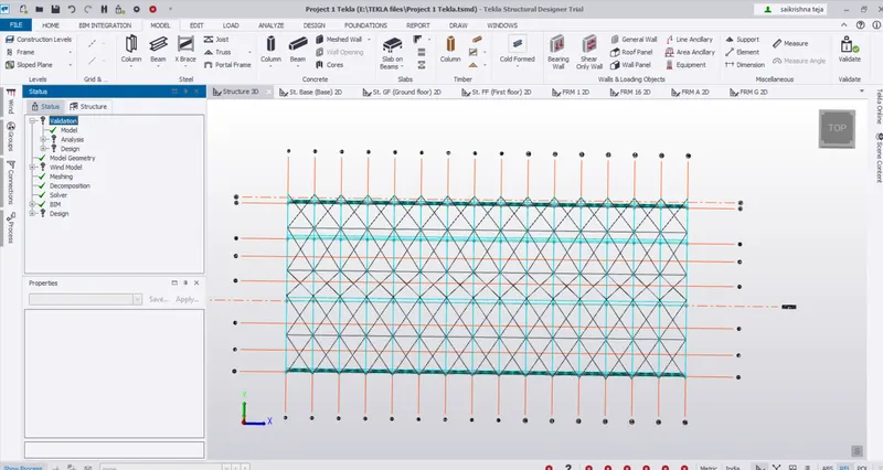
8. After Creation of Bracings Roof panels are placed over the coordinates of the X Bracings
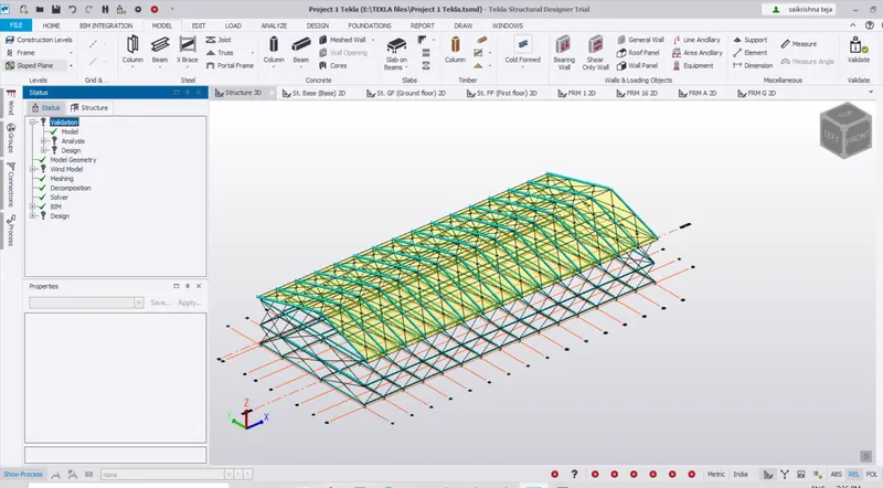
9.Wall Panels are attached to the Bracings which are connected to the wall openings and are placed over the coordinates of the X Bracings
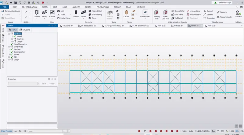
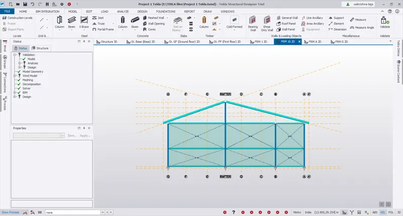
Wall Panels view in Frame 1
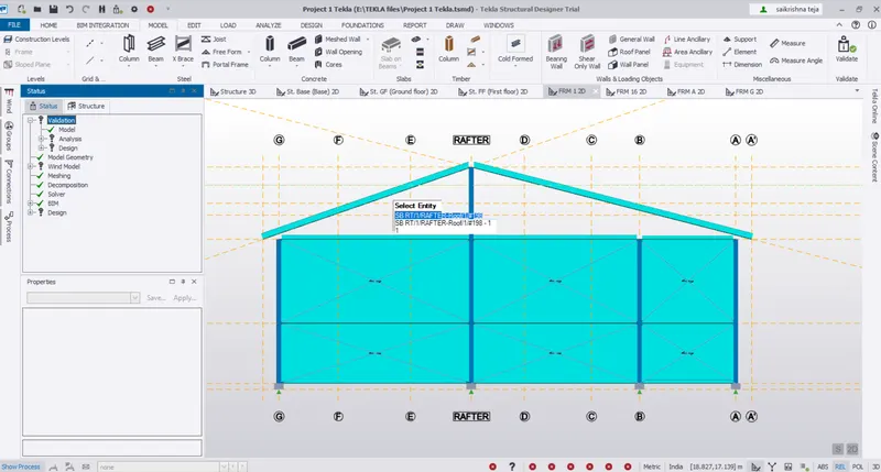
Wall Panels view in Frame 2
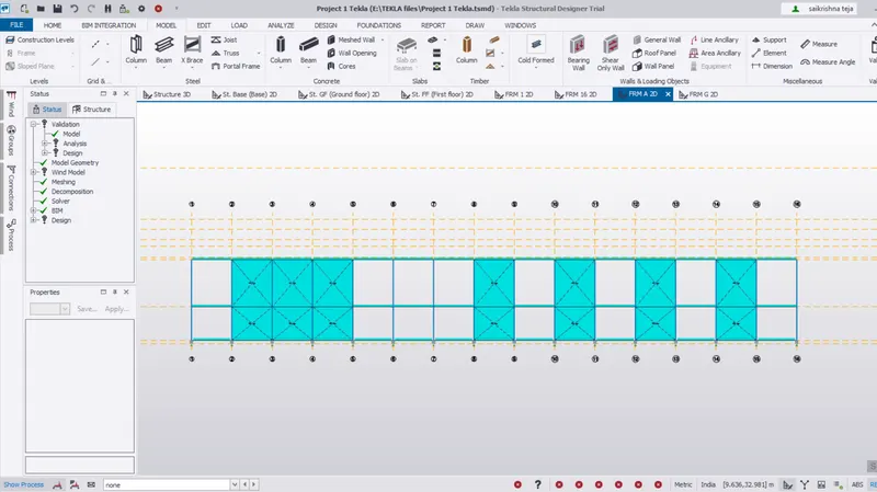
Wall Panels view in Frame A
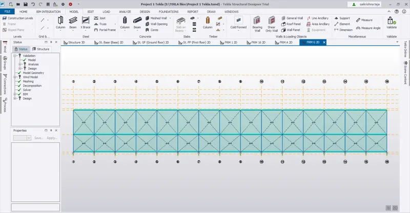
Wall Panels view in Frame G
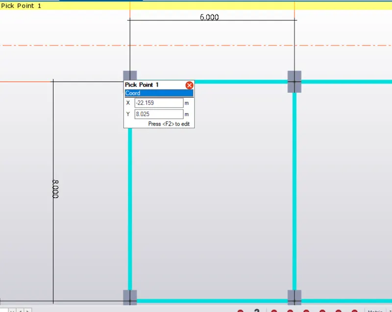
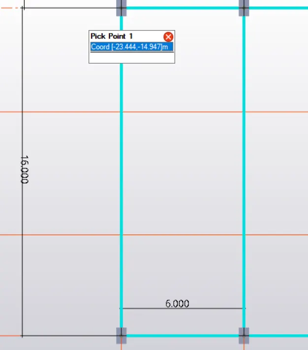
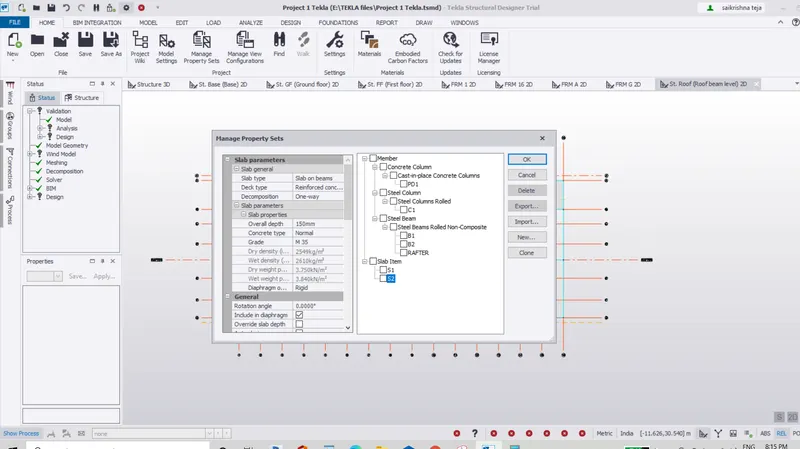
10.Now Slab Items are created S1 and S2
S1 = Two way slab
S2 = One way slab
Overall depth of slab = 150mm
Grade of concrete = M20
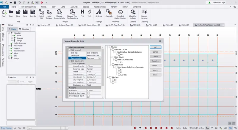
Two way slab = Ly/Lx <2
Here 8/6 = 1.33 < 2
S1 = Two way slab is applied to the respective positions
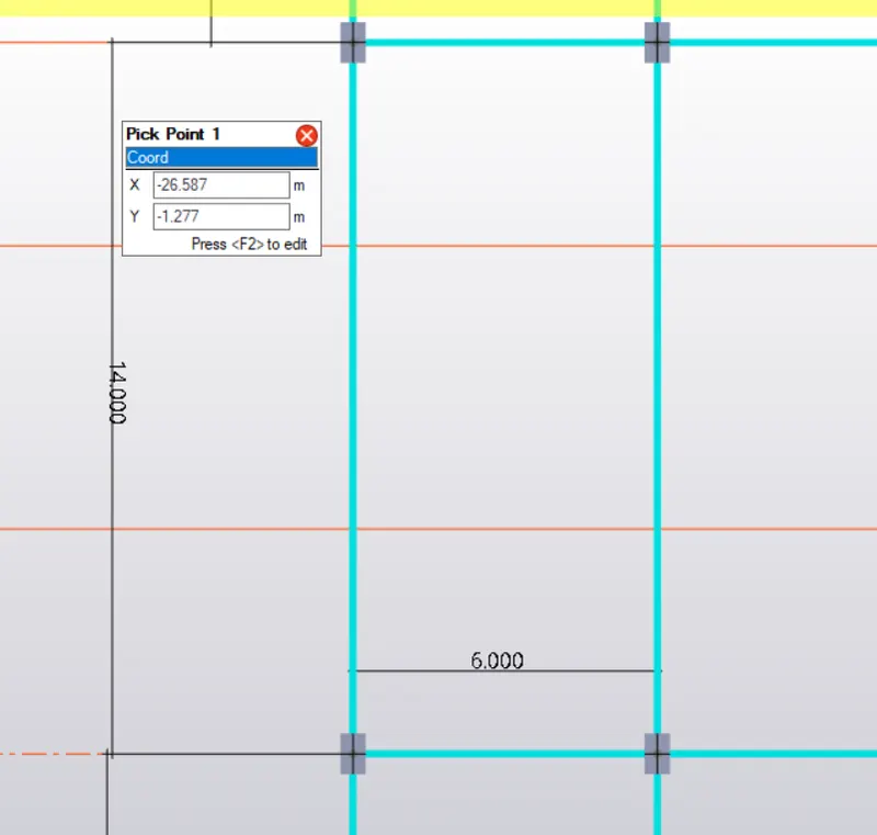
One way slab = Ly/Lx > 2
Here 16/6 = 2.67 > 2
S2 = One way slab is applied to the respective positions
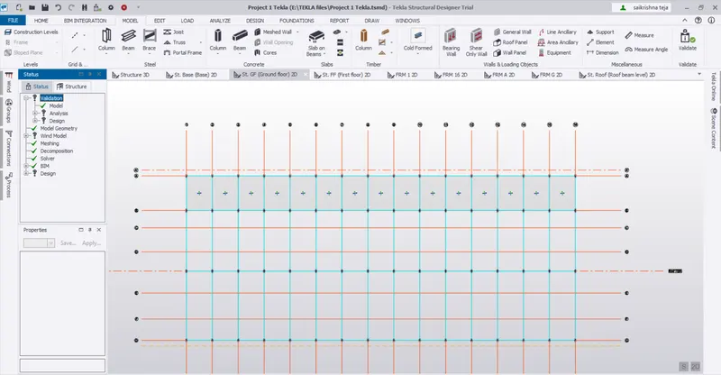
Two way slab applied@ Ground floor
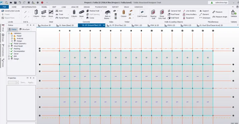
One way slab applied@ Ground floor
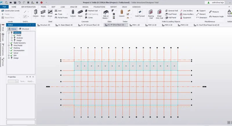
Two way slab applied @ First Floor level
Two way slab applied @ Roof of the Beam level
Details of the Structure:
Support = Fixed-Fixed (Top and Bottom)(Mx and My will be formed)
Conrete used M45
Concrete Pedestal Size PD1 = 500mm*800mm
Concrete Pedestal Size PD1 = 400mm*400mm
Steel Column C1 = UC 356*406*457
Steel Beams
B1= UB 1016*305*393 applied for Primary Beams at Ground Floor including Staircase landing Beam
B2 = UB 914*419*388 applied for at First Floor
B3 = UB 914*419*388 applied for Beams at Roof including Staircase landing Beam
B4 =ISMB 500 applied for Brackets for Crane loading at First Floor
RAFTER = UB 914*419*388 applied along the Grids 1,2,2",3,4 on the Roof
RIDGE = UB 914*419*388 applied along the Grids Roof Beam top level horizontally in X direction
UB 914*419*388 applied along the Grids on the Roof Beam top level horizontally in Y direction
Slab Items for both S1 and S2
Concrete grade M 20
Overall depth =150
Wall Bracings are added EA Equal Angles ISA 100*100*10
Roof Bracings are added EA Equal Angles ISA 100*100*10
Loads Calculation:
Unit weight of concrete = 24KN/m3
1.Dead Load:
1.Finishes Loading = 0.05*24 = 1.2 KN/m2 (Area Loading)
2.Slab load will be Designed by Software
3.Brickwall Loading
Thickness of Brickwall = 150 mm
Unit weight = 20KN/m3
Floor Height = From Ground Floor to First Floor = 5m
Brickwall loading = 0.15*20*5 = 15 KN/m
Floor Height = From First floor to Roof = 13m
Brickwall Loading = 0.15*20*13 = 39 KN/m
4.Roof Loading based on Purlin size = 1.5 KN/m2
5.Ceiling loading 0f 0.3 KN/m2
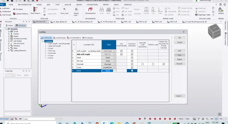
Load combinations are Generated
Dead load 1.2 KN/m2 applied on Ground Floor , First Floor , Roof
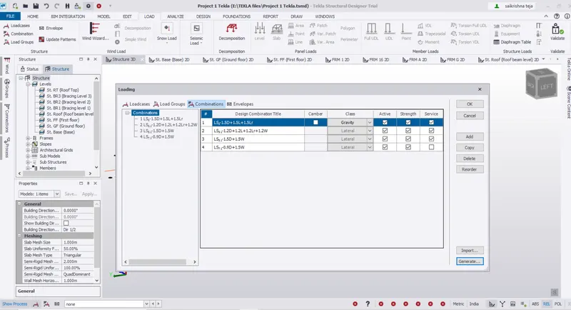
Ground Floor Rooms:
Office = 3KN/m2
Stair case = 5KN/m2
Workshop = 5 KN/m2 ( Considering Light Machinery)
Meeting Room =5 KN/m2
Pantry =3 KN/m2
Flat Roof with out access = 0.75 KN/m
Maintanance Yard = 2.5KN/m
Maintanance Room = 2.5KN/m
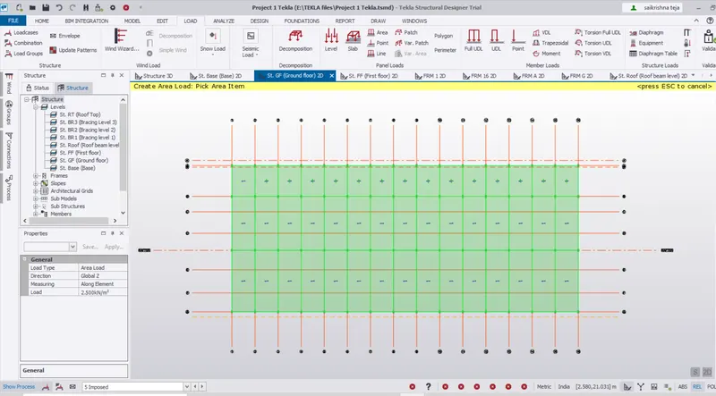
First Floor Rooms:
Staircase = 5KN/m2
Conference Room = 5KN/m2
Office =3 KN/m2
Toilet = 2KN/m2
Pantry =3 KN/m2
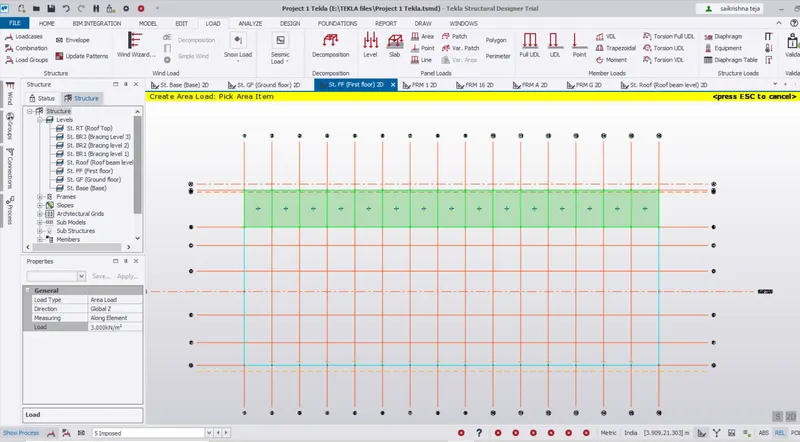
Roof :
For the 18 degree pitch apply a roof load of 1.5KN/m2 Area Loading
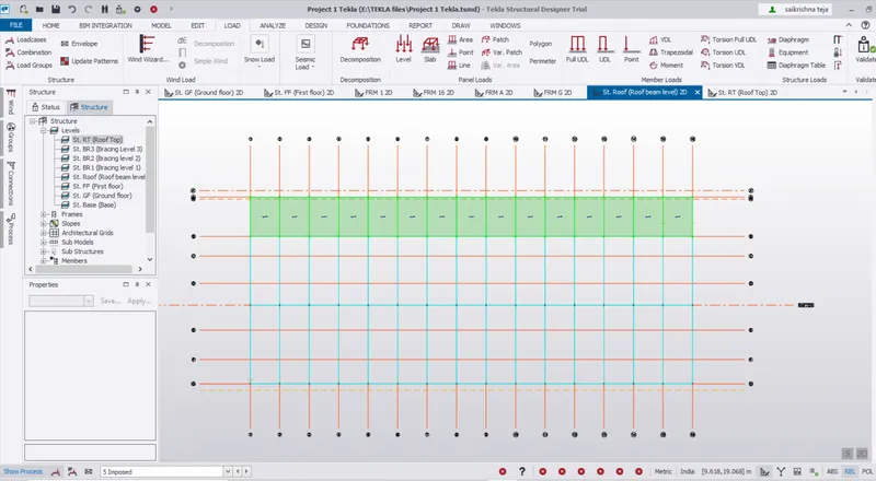
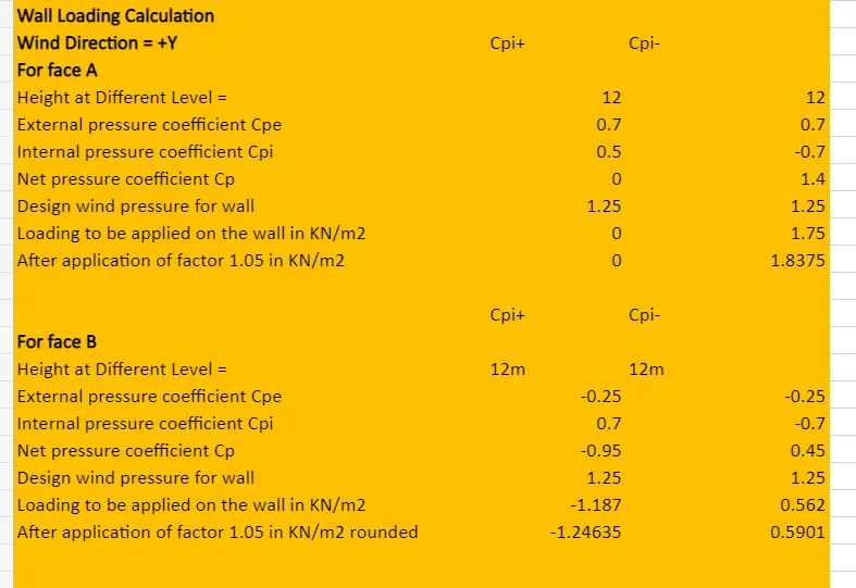
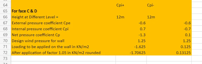
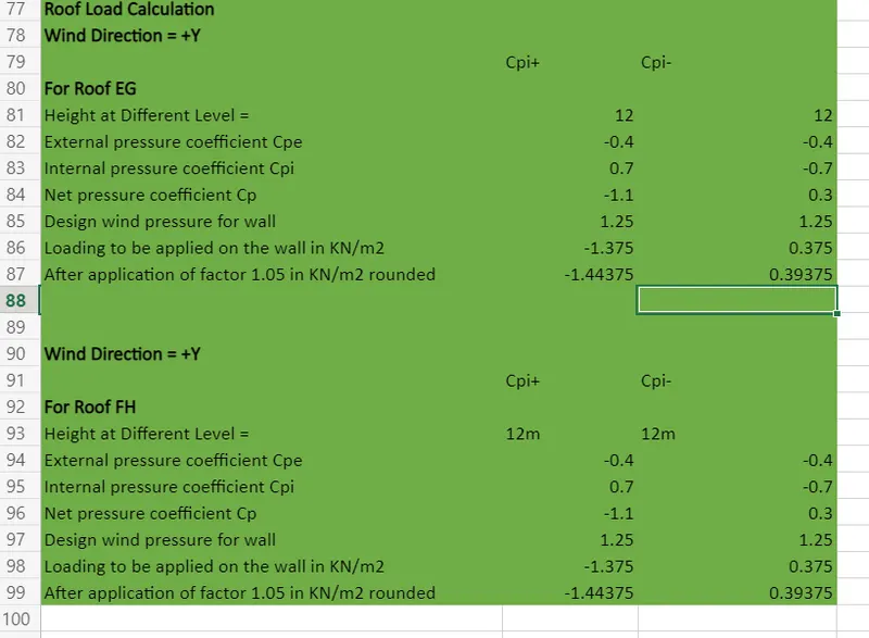
WIND LOADING:
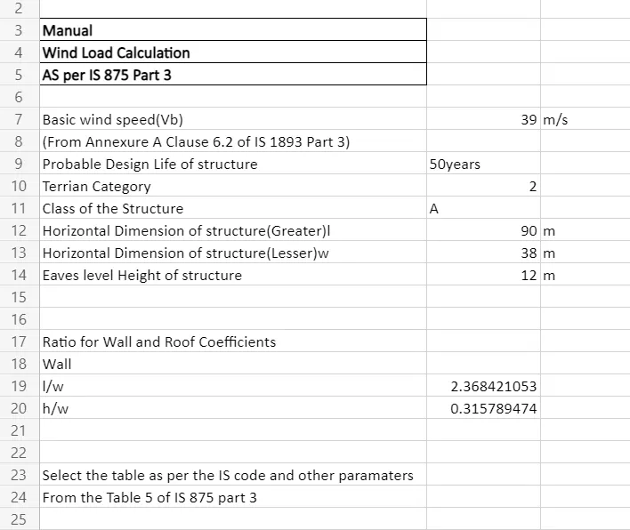
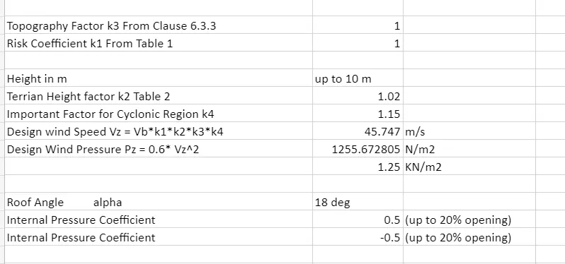
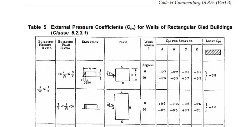
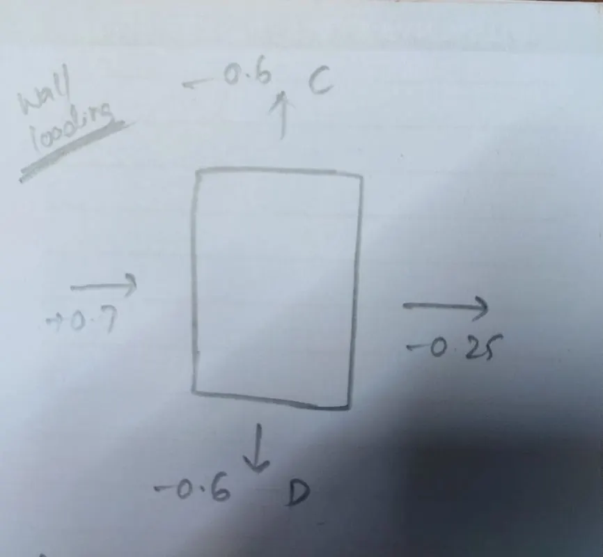
Wind wall loading
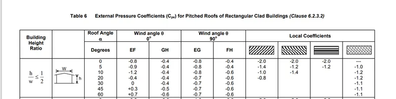
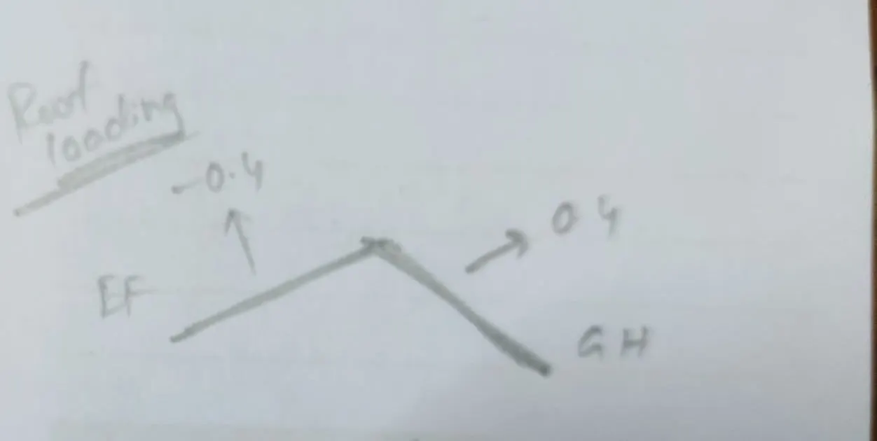
Wind Roof Loading
Crane Load Calculation:
Given that
Crane Capacity = 100 KN
Weight of trolly Car or Crab = 35 KN
Aprroximate minimum approach of the crane hook to gantry girder = 1m
c/c distance between gantry rails = 20 m
c/c distance between column = 6 m
Self weight of rail section = 300 N/m = 0.3 KN/m2
Yield stress of steel = 250 N/m2 = 0.25 KN/m2
Wheel base = 3m
To find Maximum Wheel load of the Crane
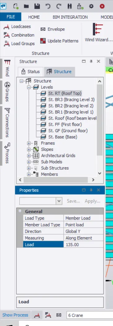
Maximum Point load on the crane = 100 + 35 = 135 KN
Apply in Y diection
(Crane capacity + weight of Crab)
Self weight of crane = 160 KN
To convert this in to UDL = (Self weight of crane/c/c distance between gantry rails)
= 160 KN/20 m = 8 KN/m
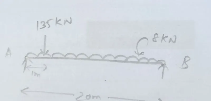
Consider moment about B
RA*20-135*19-8*20*10 =0
RA = 208.25 KN
Consider moment about A
RB*20-135*1-8*20*10 =0
RA = 86.75 KN
Maximum wheel load on each wheel = 208.25/2 = 104.125
For calculation of Maximum Bending moment
1.Considering the Dead loads
Assume self weight of gantry girder as 1.5 KN/m
Given Self weight of rail section = 0.3 KN/m
Total dead load = 1.5+0.3 = 1.8 KN/m
For absolute maximum bending moment
1.The load and
2.The resultant are equidistant from mid-span
also we can do as shown in diagram
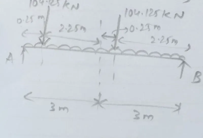
BM due to deadload M1 = wl2/8 = 1.8*6^2/8 = 8.1 KN-m
2.Considering the Live loads
Taking moments about B
RB*6 - 104.125*5.25 - 104.125*2.25 = 0
RB = 130.15 kN
Taking moments about A
RA*6 - 104.125*3.75 - 104.125*0.75 = 0
RA = 78.09 KN
Maximum Bending Moment will be below wheel load at M2 = RA x 2.25
= 78.09*2.25
= 175.70 kN-m
Impact load = 10% of maximtim static wheel load
Maximum BM due to impact, M3 = 10% of M2
= 0.1*175.70 = 17.570 kN-m
M = M1 + M2 + M3 = 8.1+175.70+17.570 = 201.37 KN-m
For calculation of Maximum Shear Force Due to Vertical Loads
1.For Dead load
Shear force due to self weight V = wl/2 = 1.8*6/2 = 5.4 KN
For maximum shear force due to wheel loads, one of the wheel loads is at the support.
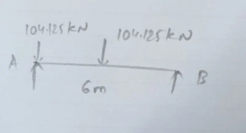
2.For Live loads
Taking moments about B
RA*6 - 104.125*6- 104.125*3 =0
RA = 156.18 kN
3.For Impact loads
Impact load = 10% of maximum wheel load
Maximum shear force due to impact =0.1*156.18 = 15.618 KN
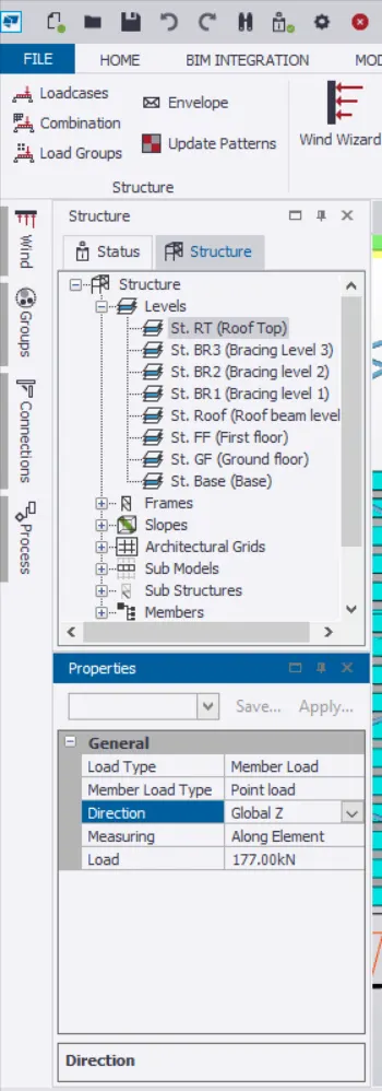
Total Maximum shear Force = 1+2+3 = 5.4+156.18+15.618 = 177.2 KN
Apply in Z direction
Lateral Load Analysis
Lateral load = 5% of (the weight of the trolley + weight lifted by the crane)
= 0.05*(100+35)
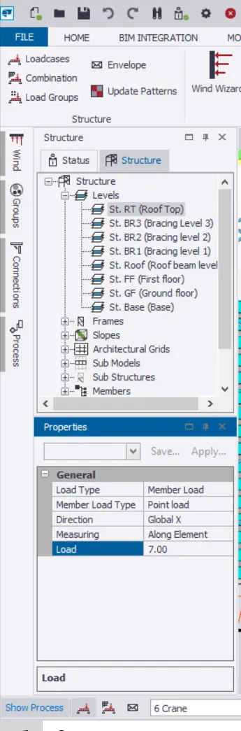
= 6.75 KN
For one wheel, the lateral load = 3.375 KN
since we have four wheels)
The maximum bending moments and shear force can be calculated by proportion method :
Maximum Horizontal reaction due to lateral force by proportion at A
= Lateral force*lateral force due to reaction at A due to vertical load/Max wheel load due to vertical load
=3.375*130.15/104.125
=4.21 KN
Maximum Horizontal reaction due to lateral force by proportion at B
= Lateral force*lateral force due to reaction at B due to vertical load/Max wheel load due to vertical load
=3.375*78.09/104.125
= 2.54 KN
Total Lateral load = 4.21+2.54 = 6.74 KN
Apply in X direction
Bending moment due to lateral load = 3.375*15.18/104.125 = 5.06 KN-m
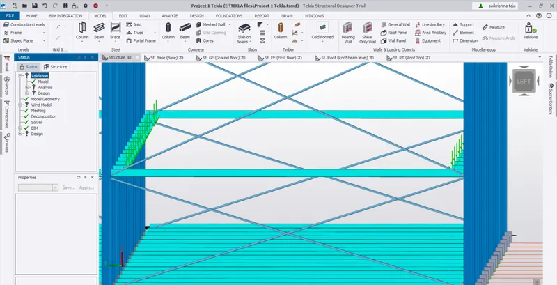
Crane load application
Final Result:
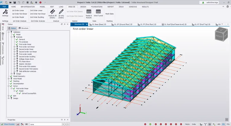
Static Result:
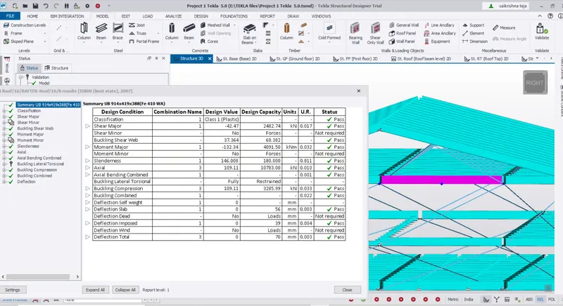
For Beam
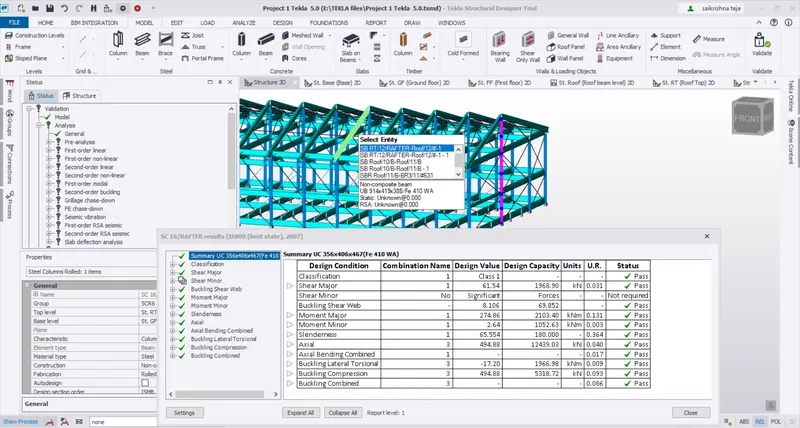
For Column
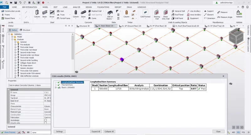
For Pedestal Concrete Column
For Rafter