Week 7 Challenge
1. Setup model for RC building design and based on following parameters for cover
|
MEMBERS |
IN CONTACT WITH GROUND |
ABOVE GROUND |
|
Column |
50mm |
40mm |
|
Beam |
30mm |
25mm |
|
Slab |
30mm |
25mm |
|
Pilecap |
75mm |
|
|
Foundation |
50mm |
Answer:
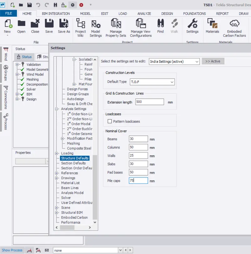
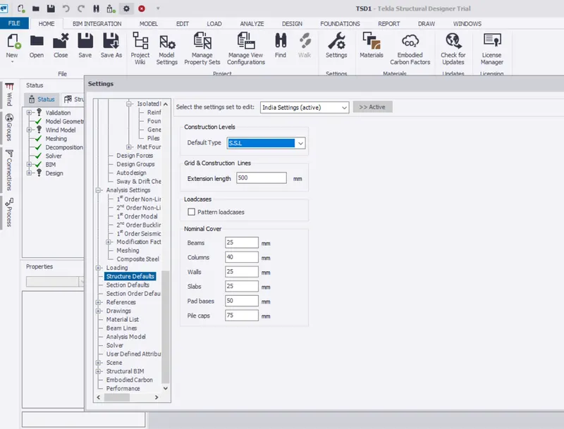
The Nominal covers are provided as the Following:
Nominal Covers for the RC Building in contact with the Ground is considered as T.O.F = Top of the Foundation
Nominal Covers for the RC Building above the Ground is considered as S.S.L = Structural Slab level
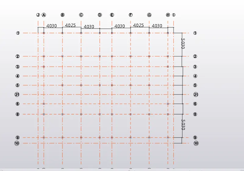
2. Model grids as per the attachment 2,2.1 and 2.2
Answer:
Construction Level for the given RC Building is considered as below:
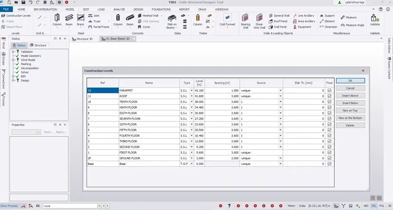
Grid Levels are taken as per the placement of the Beam Column Joint and column positions.
3. Study the layout and write a summary for general arrangement of the structure
Answer:
The Layout is considered from the Video is a Multi-storey Building Building having 10 Storeys.
The Building has Flat Roof and a Parappet Roof
It has 12 Water storage tanks at the Roof.
The plan of the Building shows the Residential Flats.
Each Floor has 4 number of individual Flats.
The Plan for the each flat shows:
3 Bedrooms
1 Dining room
1 Drawing room
1 Kitchen
1 Puja Room
2 Toilets
1 Verandah
Lift access and Stairs is also provided for all floors.
The main important things to be noticed while the Designing of the elements is:
The Architectural view and the Aesthetic view should not get hinder due to Structural elements.
The Obstacles formed due to mandatory Structural elements are to be get resolved
These Structural obstacles should be resloved by supporting elements which help to consider the Strength of the Structure without compromising with the Design and Strength.
For General Arrangement of the Structure:
For the General arrangement we have consider Strcutural drawings for placement of the Individual elements.
Construction levels are defined as given in the Architectural drawings
Grids are drawn as per the plan.
1.The placing of the elements starts with Fixed-Fixed supports at the Base Levels
2.Columns are placed at the required locations as per the plan.
3.The sizes of the column are considered 400mm*400mm
4.Then Beams are placed connecting the columns at the required levels.
5.The sizes of the Beams are considerd as 230mm*600mm
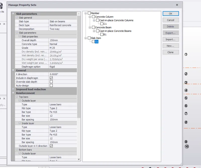
6.Now slabs are defined with the thickness of 150mm ; Slab on Beams are provided with Two Way slab Design.
7.For the Lift core Pit Shearwall Design is made to have the strength increase.
4. Model RC columns, beams and slabs as per your general arrangement
Answer:
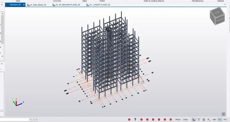
Columns are posited from the Base to the Parappet Wall.
Beams are drawn from First Floor to the roof.
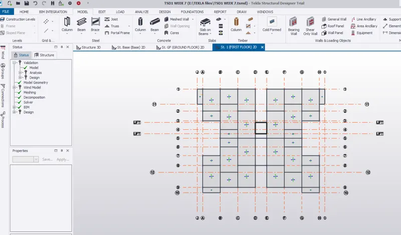
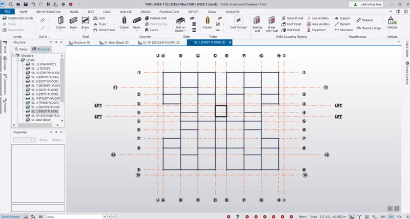
RC Columns shown in plan are placed accordingly with the distances mentioned as per the Grids
The Columns are Joined with the Beam as shown below @ First Floor
Beams and Columns in 3D
Property sets are defined for Columns,Beams and slabs.
View of Two way Slab in 3 D
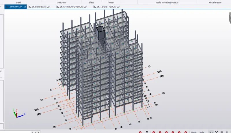
View of Two way Slab in 2 D