Creating an Architectural plan for the provided plot size and develop relevant basic structural drawings
Aim:
To Design and Draft a layout of a residential building with the given details.
Introduction:
Developement of Residential house Drawings which consists of
- Architectural Drawing
- Structural Drawing
Architectural Drawing include a Floor Plan, Elevation of the Floor plan and Section of the Building
Structural Drawings include Column Layout, Beam and Footing Plan
As per the requirement the house plan is taken as East Facing.
Given Plot size is 60’x20’(18.3m x6m)
Procedure:
The step by step Procedure for Drawing a Achitectural plan
1.PLAN OF THE RESIDENTIAL HOUSE
Using Commands starting with
UNITS (Inches)
LIMMAX (To limit the Entire workspace of the as per the Requirement)
Creating Layers like
- External walls
- Internal Walls
- Doors
- Windows
- Dimensions
- Text
- Columns
XLine command for Drawing External walls to create Boundaries
Line command for Internal walls
Trim command for Trimming all the unnecessary lines
Extend command for Extension of lines where ever required
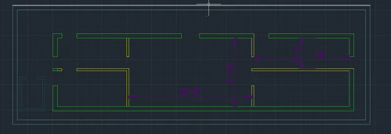
Dimension Command for Creating all the Dimensions to the drawn Rooms
Dimensionstylemanager command for editing the Dimension styles like Size of the arrows,size of text,Text Fit
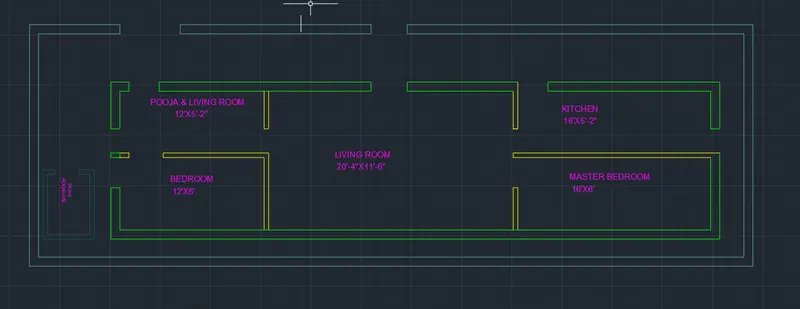
Blocks Command For creation of Doors and Windows
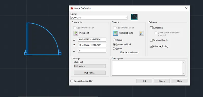
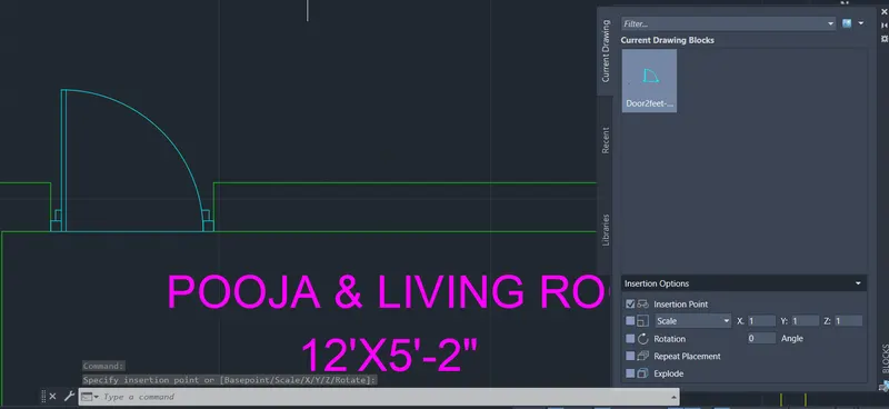
Insert Command for Inserting the Door and Window of the suited fit dimension
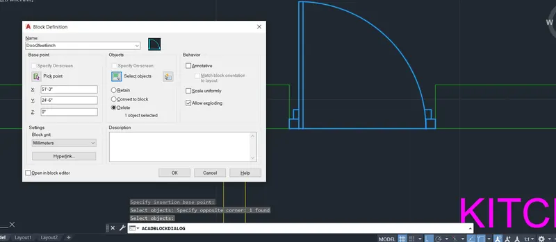
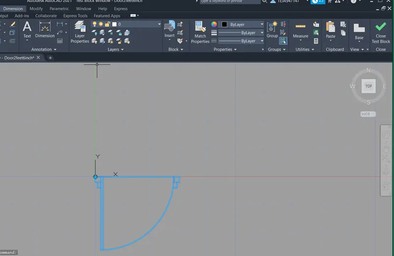
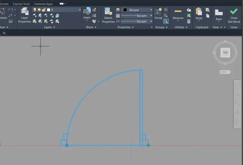
DynamicBlock Command for creation Dynamic Doors and windows
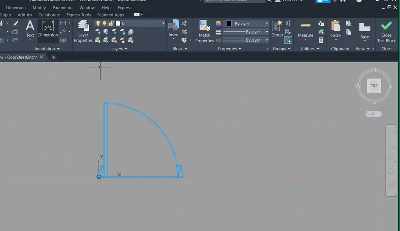
Flip action for DynamicBlock is assigned and checking in Test Block
2.RESIDENTIAL HOUSE ELEVATION
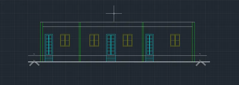
Elevation of the Residential is created by using Xline Command and Extend command
The lines are traced and respectve elements like Door and Window are drawn with reference to the External walls and Internal walls;
Ground level,Plinth level,Sill level,Lintel level,Slab level,parappet wall levels are imagined and drawn.
Commands used are
Xline to draw reference lines
Trim to remove the unnecessary lines
Extend for the Extension of the lines
Line command for other simple connections
DIMLINEAR and DIMCONTINUE for the drawing dimensions
Array command for marking the lines below the Ground level
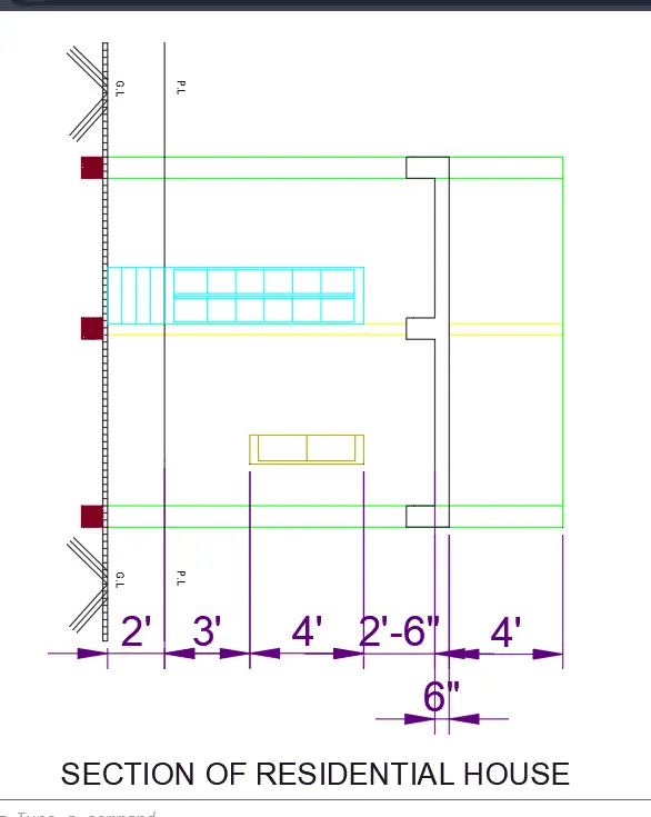
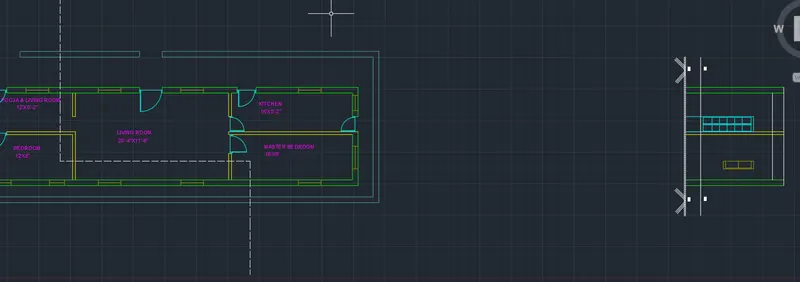
3.RESIDENTIAL HOUSE SECTION DRAWING
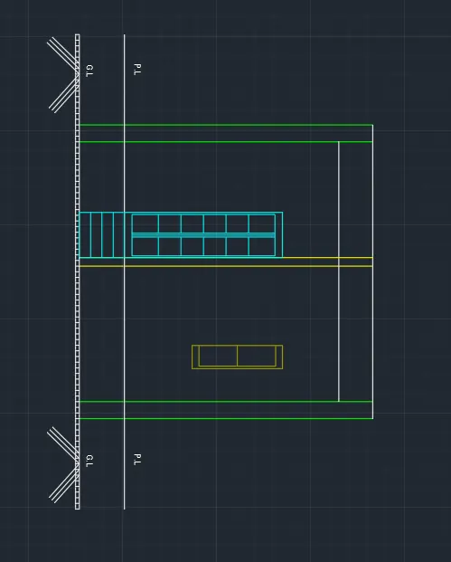
A section is cut for the Plan Drawing and it is replicated to show the view after cutting the section which is named as SECTION DRAWING,
Same as ELEVATION DRAWING the reference lines are drawn from the section of the PLAN DRAWING and the elements of the cut view are represented in the CUT SECTION DRAWING
All the levels which are mentioned in the ELEVATION DRAWING are placed in this SECTION DRAWING also.
The view has the Clear picture of the cut Footing,Columns,beams,slab,Door,Window elements
Commands used are
Xline to draw reference lines
Trim to remove the unnecessary lines
Extend for the Extension of the lines
Line command for other simple connections
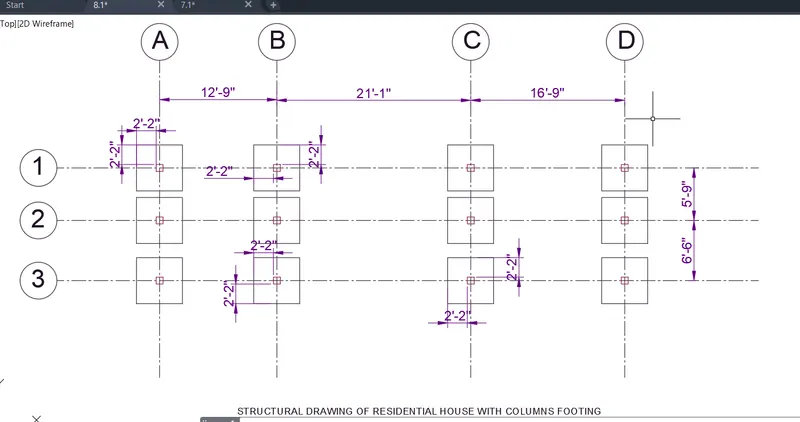
4.RESIDENTIAL HOUSE STRUCTURAL DRAWING
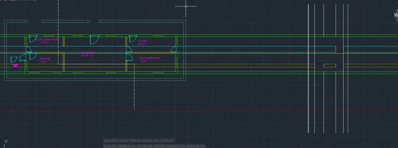
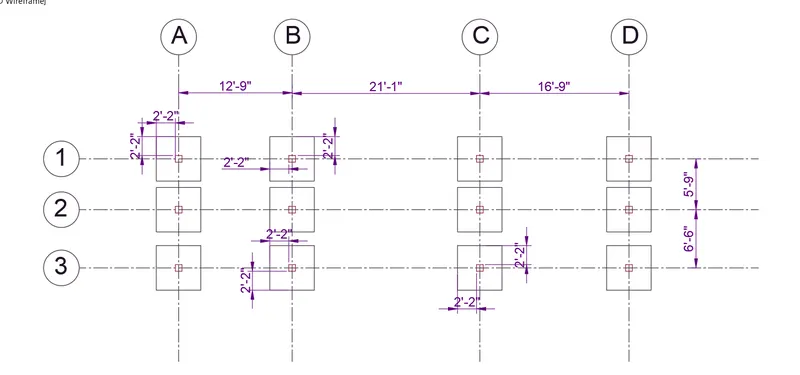
The section of the STRUCTURAL DRAWING includes the Plinth Beam, cloumn and Footing Layout which are drawn from the reference of the Plan Drawing.
Commands used are
REC for Column and Footing
LINE command for Plinth Beams
Centreline Command for marking Centre lines for the reference which are named as GRIPS
5.Some other Commands are used like
ADC command for furnitures and Plumbing Fixtures
RESULT:
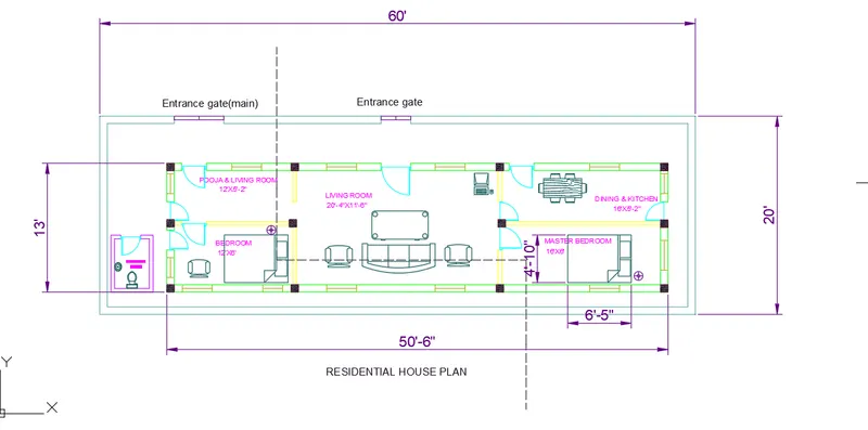
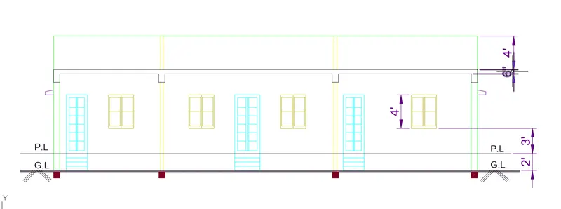
ELEVATION OF RESIDENTIAL HOUSE