Week 1 Challenge
Question 1
Project Workspace – How to access and usage
1.Open Tekla software
2.Click on NEW , to create the new window for generating Models.
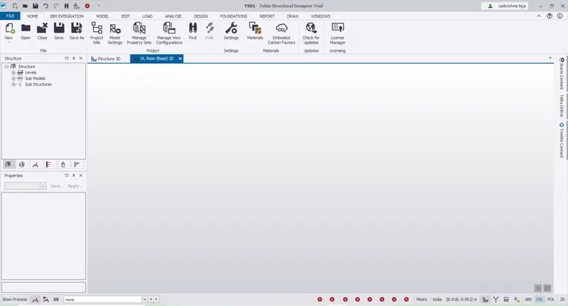
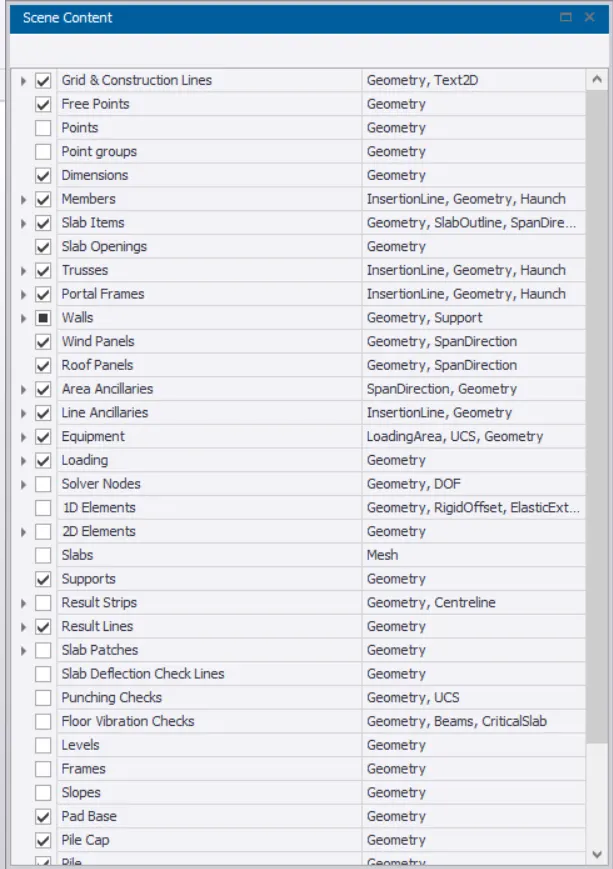
Scene Content – Demonstrate the use of scene content
Go to windows>Properties window > Scene Content
It is used for check/uncheck the boxes for selection of materials.
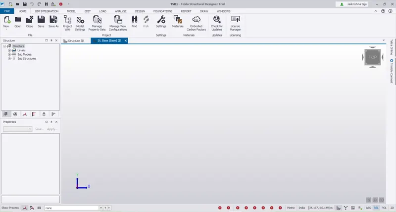
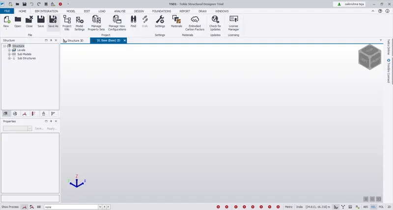
Create two scene views
2-D view
3-D view
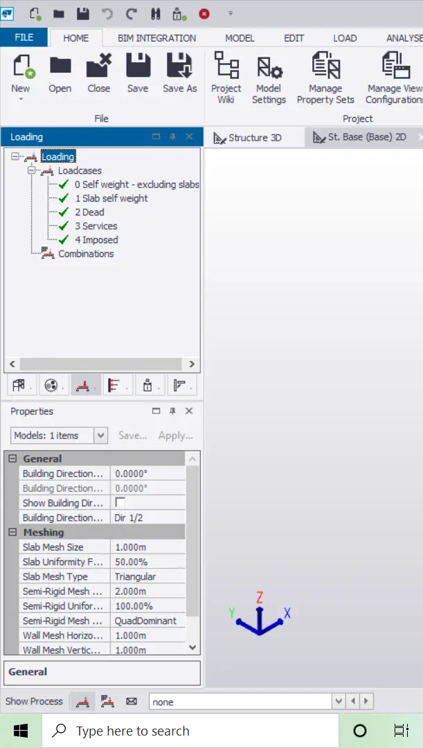
Loading drop list- How to access
Go to Windows> Loading window
1.click on project work space>loading
2.Show Process for Different load cases, Load combinations , load patterns
Properties windows – how to access and usage
Go to Windows > Properties window
It is used to change the properties and for assigning them for different elements of the structure.
Question 2
2. Create a new file in TSD and set up the settings for a steel building to have member grade FE410 and concrete grade of M30 as per IS codes. The covers for the members to be as per the following input: -
|
MEMBERS |
IN CONTACT WITH GROUND |
ABOVE GROUND |
|
Column |
50mm |
40mm |
|
Slab |
30mm |
25mm |
|
Pile cap |
75mm |
|
|
Foundation |
50mm |
Answer:
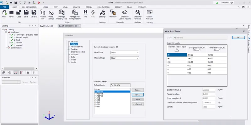
Steel Grade FE410
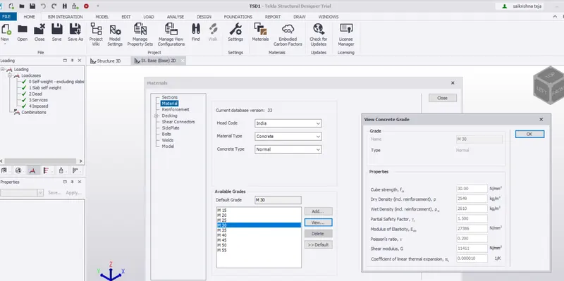
concrete grade of M30
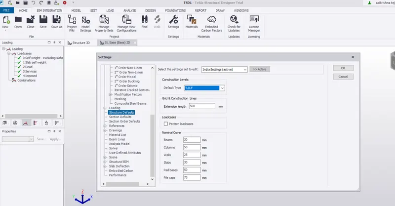
Nominal cover
IN CONTACT WITH GROUND
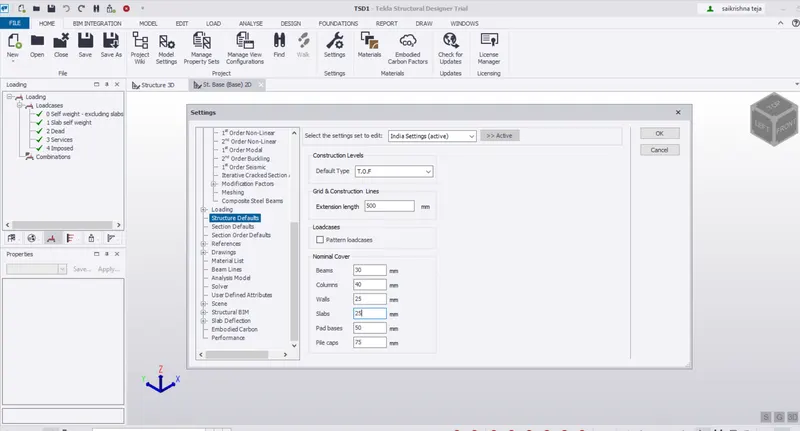
Nominal cover
ABOVE GROUND
3. With reference to the input drawing as per Attachment 1, 1.1, and 1.2 and study the steel building plan and summarize your understanding of the plan. Based on your study assume and explain the location of columns and beam and develop a hand sketch for each plan
Answer:
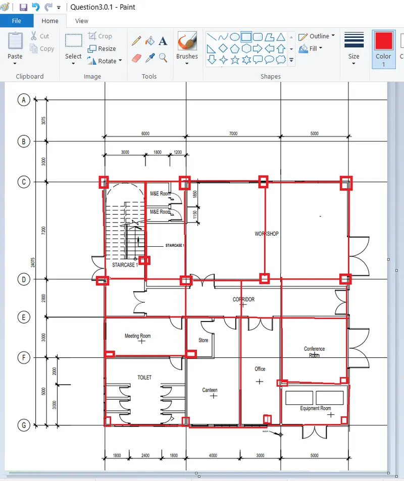
From the attachment 1
Ground floor Plan
It is observed that the in X direction need to provide 4 columns and 3 Beams spanning 6m,7m,5m each
Therefore Long span Beams are to be placed in X direction
In Y direction need to provide 4 columns and 3 Beams spanning 7.2m,2.8m,3m,5m each
Also if necessary secondary Beams can also be provided in between the primary Beams.
For the staircase a secondary Beam is provided in the middle.
For the Equipment room the placement of the Top left corner column need to be considered as a typical one where the column support is not in line with the other columns although it placed on the grid.
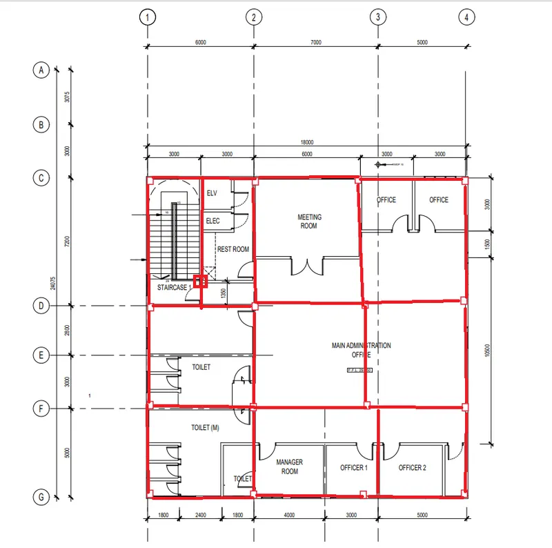
From the Attachment 1.1 = First floor plan
The placement of Beams and columns are similar to that of Ground floor only the column height varies according to the slope of the Roof.
Individual Beams are drawn as per the requiremnt to reduce the larger spans
Also if necessary secondary Beams can also be provided in between the primary Beams.
For the staircase a secondary Beam is provided in the middle.
Here it is given the placement of the column for the OFFICER 2 room is already decided; it may not match with the Ground floor column so the column placement need to be changed in either of the floors.
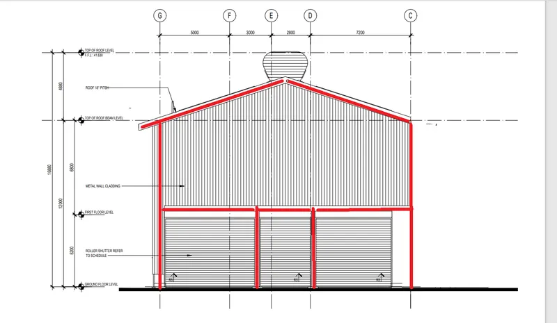
Attachment 1.2 = Elevation
From the Elevation it is observed that the height of the column is adjusted according to the Roof level
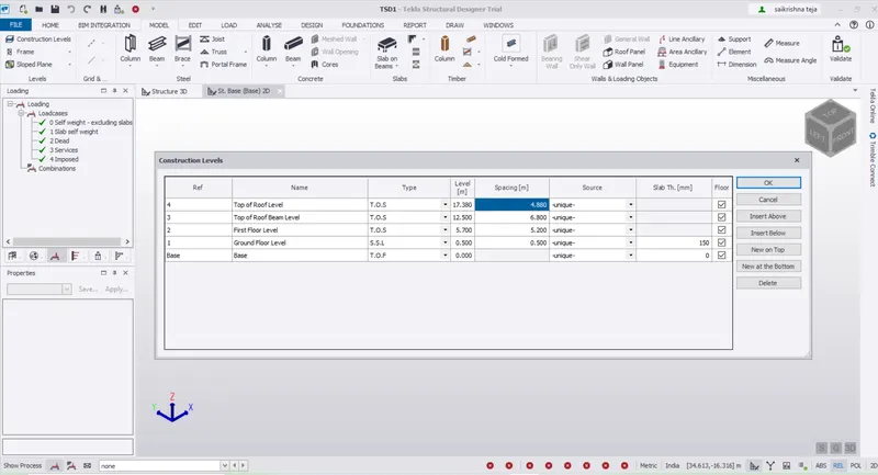
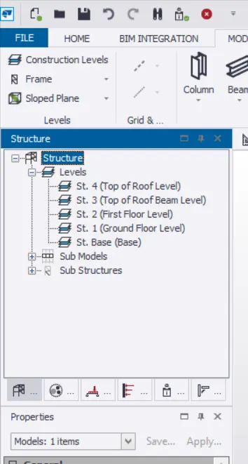
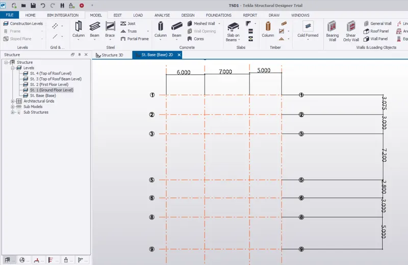
4. Model grid lines and construction levels as per Attachment 1. 1.1 and 1.2. All dimensions are in mmThe base level to be 500mm below ground level.
Answer: