Week 10: Project 1 - FULL HYDRO case set up (PFI)
AIM
The aim is to simulate the no hydrodynamic case of port fuel injected engine
OBJECTIVES
- Full simulation of working IC Engine
PORT FUEL INJECTED ENGINE
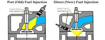
Port Fuel injection is when fuel (either gasoline or diesel fuels) is injected prior to the valve and cylinder, where the combustion happens. Back in the early 1900s, Bosch and Clessie Cummins (yes, of Bosch parts and Cummins diesel), decided to improve upon Rudolf Diesel’s original air-blasted system by injecting fuel right into the intake. The intake valve will have a fuel injection system that sprays fuel into the air coming into the engine. From there the spark plugs ignite the pressurized slurry of air and fuel, pushing the cylinder head down and spinning the crankshaft. Now, this is happening at each of the cylinders, so if you have a V6 engine with port injection, and it happens so quickly that you won’t even notice the cycle except by noise.
Port injection sprays the fuel into the intake ports where it mixes with the incoming air. Port injection systems are much cheaper to manufacture. The injectors are not exposed to the high heat and pressure of the combustion chamber and they don’t have to handle high fuel pressures. Port injection systems typically operate in the 30 to 60 PSI range, which is dramatically lower than direct injection systems. Support systems such as fuel pumps are also cheaper, because fuel pressures are lower. Port injection systems spray the fuel on the backside of the intake valve and the fuel has to wait till the valve opens. The fuel sprayed on the backside of the intake valves, also cleans the valves. The injectors are often mounted in the intake manifold runners and the fuel sits in the runners until the intake valve opens and the mixture is pulled into the engine cylinder.
HYDRODYNAMIC CASE OF PFI ENGINE
Geometry
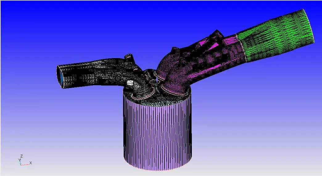
BOUNDARY CONDITIONS
Piston
- Boundary - WALL
- Surface Movement - Moving
- Temperature = 450 K
- Piston Motion - piston_profile.out
Inflow
- Boundary - INFLOW
- Pressure = 101325 bar
- Temperature = 363 K
- Mixture - Air
Liner
- Boundary - Wall
- Surface Movement - Fixed
- Temperature = 450 K
Cylinder Head
- Boundary - Wall
- Surface Movement - fixed
- Temperature = 450 K
Exhaust Port
- Boundary - Wall
- Surface Movement - Moving
- Temperature = 450 K
Outflow
- Boundary - OUTFLOW
- Pressure = 101325 bar
- Temperature = 800 K
- Mixture - Air
- CO2(mass fraction) - 0.192304
- H2O(mass fraction) - 0.088559
- N2(mass fraction) - 0.719137
Exhaust Valve Top
- Boundary - Wall
- Surface Movement - Moving
- Temperature = 525 K
- Profile - exhaust_lift.in
Exhaust Valve Angle
- Boundary - Wall
- Surface Movement - Moving
- Temperature = 525 K
- Profile - exhaust_lift.in
Exhaust Valve Bottom
- Boundary - Wall
- Surface Movement - Moving
- Temperature = 525 K
- Profile - exhaust_lift.in
Intake Port
- Boundary - Wall
- Surface Movement - Moving
- Temperature = 425 K
- Profile - exhaust_lift.in
Intake Valve Bottom
- Boundary - Wall
- Surface Movement - Moving
- Temperature = 300 K
- Profile - inlet_lift.in
Intake Valve Angle
- Boundary - Wall
- Surface Movement - Moving
- Temperature = 300 K
- Profile - inlet_lift.in
Intake Valve Top
- Boundary - Wall
- Surface Movement - Moving
- Temperature = 300 K
- Profile - inlet_lift.in
Spark plug Terminal
- Boundary - Wall
- Surface Movement - Fixed
- Temperature = 600 K
Spark Plug
- Boundary - Wall
- Surface Movement - Fixed
- Temperature = 600 K
Intake Port
- Boundary - Wall
- Surface Movement - Fixed
- Temperature = 425 K
Results
Peak pressure plot
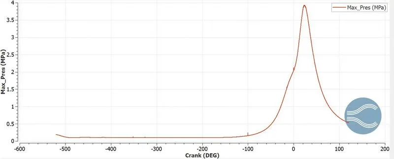
When engine starts, pressure inside the cylinder is almost constant. Pressure in the cylinder sharply rises after 0 degree and then falls. In this period both the valves are closed and the fuel air mixture is compressed by the piston to get this sharp curve of rise and fall in pressure.
Mean Temperature
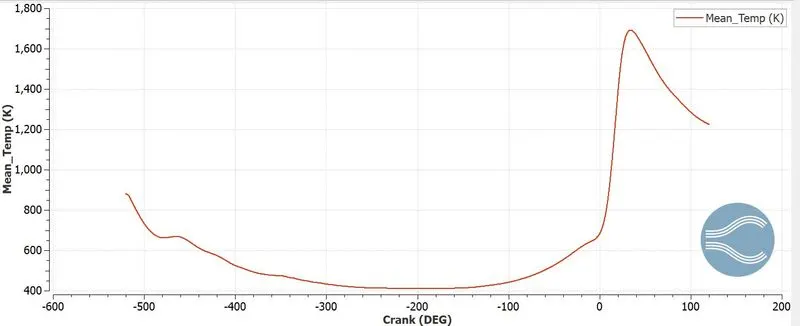
With a high mean temperature of 1800K inside the cylinder, it reaches high temperatures due to the combustion of fuel and the sharp rise in pressure as well.
Volume
Mass
Heat Release Rate
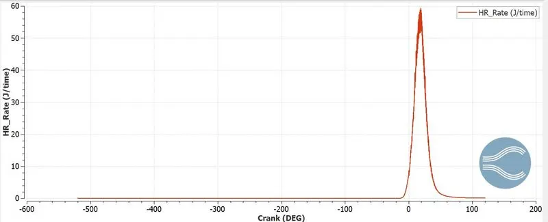
Heat Release Rate (HRR) is the rate at which fire releases energy - this is also known as power. HRR is measured in units of Watts (W), which is an International System unit equal to one Joule per second. Depending on the size of the fire, HRR is also measured in Kilowatts (equal to 1,000 Watts) or Megawatts (equal 1,000,000 Watts).
Integrated Heat Release
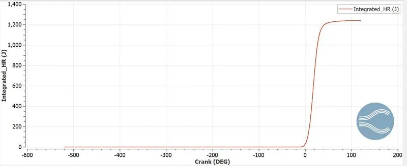
This plot helps us to judge the amount of heat being extraceted inside the engine.
Fuel Spray
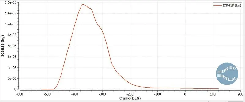
EMISSIONS PLOTS
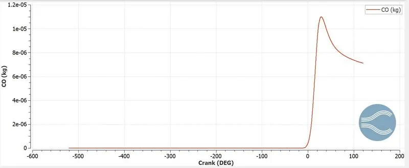
Carbon monoxide
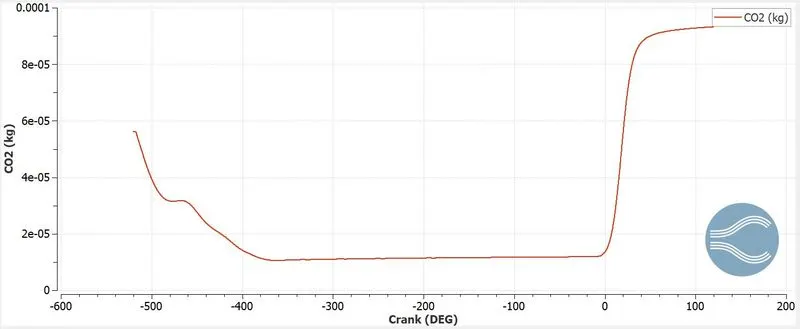
carbon dioxide
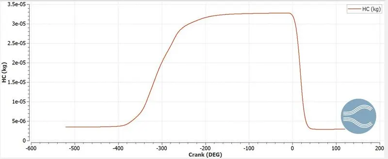
Unburnt Hydro Carbon
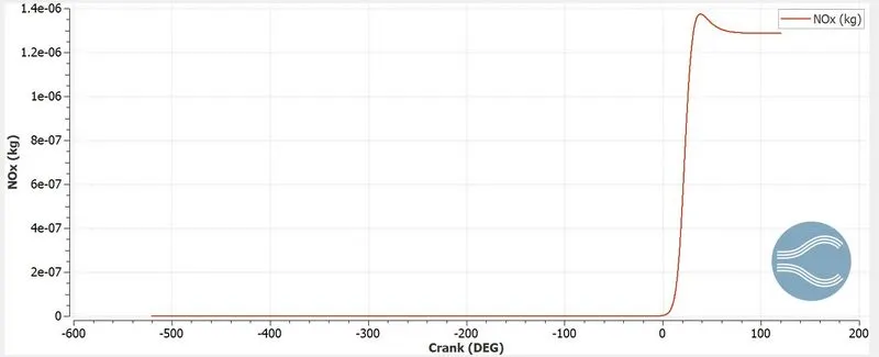
Nitrogen oxides
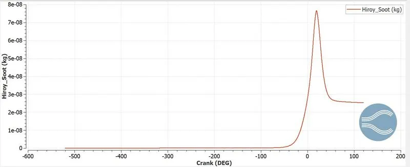
Soot
Compression Ratio of Engine
In a combustion engine, the static compression ratio is calculated based on the relative volumes of the combustion chamber and the cylinder; that is, the ratio between the volume of the cylinder and combustion chamber when the piston is at the bottom of its stroke, and the volume of the combustion chamber when the piston is at the top of its stroke.The dynamic compression ratio is a more advanced calculation which also takes into account gasses entering and exiting the cylinder during the compression phase. The compression ratio is a fundamental specification for combustion engines.
In a piston engine, the static compression ratio ( ) is the ratio between the volume of the cylinder and combustion chamber when the piston is at the bottom of its stroke, and the volume of the combustion chamber when the piston is at the top of its stroke.It is therefore calculated by the formula

Where:
 = displacement volume. This is the volume inside the cylinder displaced by the piston from the beginning of the compression stroke to the end of the stroke.
 = clearance volume. This is the volume of the space in the cylinder left at the end of the compression stroke.
can be estimated by the cylinder volume formula
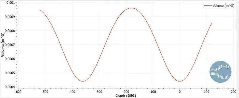
From the volume plot
Maximum Volume = 0.000574121 `m^3`
Minimum Volume = 0.0000575786 `m^3`
`CR = 0.000574121/0.0000575786`
`CR = 9.971`
COMBUSTION EFFICIENCY
From the integrated heat release curve, we get heat released is 1241.06 J.
Theoretical energy = 0.00003*43.44e6 = 1303.2 J
`Combustion Efficiency = 1241.06/1303.2xx100`
`Combustion Efficiency = 95.21%`
SIGNIFICANCE OF CA10, CA50 & CA90
However, to understand precisely the combustion status in different DFD modes, the parameters CA10 and CA50 and CA90 are specified here. The CA10 and CA50 are defined as the position of the crank angle (deg) at which the cumulative heat release reaches at 10% and 50%, respectively. The physical significance of CA10 is that it is used to identify the start of ignition in a diesel engine, whereas the CA50 indicates the end of premixed combustion and the start of diffusion combustion of fuel used in the engine. The physical significance of CA10 is that it is used to identify the start of ignition in a diesel engine, whereas the CA50 indicates the end of premixed combustion and the start of diffusion combustion of fuel used in the engine. Higher the difference between CA10 and CA50 (CA50-CA10), higher will be the combustion duration and vice versa.
HEAT TRANSFER MODEL
In CFD simulation of PFI engine, the thermodynamic data of the species is provided as the input data which is used to predict the reaction rate of species in the domain and temperature change of species. But the thermodynamic data of the solid parts of the engine is not provided as input data for combustion simulation. Hence, the wall temperature of solid parts of the engine is not predicted in combustion simulation. Thus, a heat transfer model is required to predict the wall temperature of solid parts of engine where thermodynamic properties of solid is provided as the input data. The conjugate heat transfer model predicts the temperature of wall due to the interaction between the burnt species and solid parts of the engine.
ENGINE POWER AND TORQUE
From Engine Performance Calculator
`W = 468.646`
`N= 3000/60rps`
`N = 50rps`
Therefore the number of cycles completed in one second is 50
one degree of rotation completed = `1/[50xx360]`
Time taken for 240.199 degrees = `1/[50xx360]xx240.199`
Power is given by
`P = W/t (W)`
`P=frac[468.646xx50xx360][240.199]`
`P = 35119.33 W`
Torque of the engine is calculated from the below formula
`P=(2pi NT)/60`
`35119.33=frac[2xxpixx3000xxT][60}`
`T=111.788N-m`
Animation Files
CONCLUSION
- The operation of engine was simulated on Converge CFD
- Power and torque can be estimated with accurate models
- Compression ratio of cylinder was calculated