Ahmed Body Simulation
AIM
The aim of this challenge is to simulate the external flow over a ahmed body
OBJECTIVES
The main objectives of this challenge are
- Generation of the velocity and pressure contour plots for the flow over the ahmed body
- Significance of wake region and the point of separation in aerodynamics
- Drag coefficient plots to analyse the drag acting on car wall
- Vector plot study for wake region formation and to analyse the point of separation
AHMED BODY
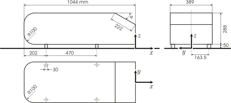
The Ahmed body was described originally by S. R. Ahmed in 1984. Three main features were seen in the wake:
1. The A recirculation region that is formed as the flow separates at the top of the vertical back surface of the model
2. The B recirculation region that is formed due to the separation at the base of the model.
3. The c-pillar vortices that form as the vorticity in the side boundary layers roll up over the slant edges.
The wake was shown to be highly dependent on slant angle. For slant angles less than 12°, the flow remains attached over the the slant. The flow is essentially two-dimensional and has low drag. Between 12° and 30° the flow becomes much more three-dimensional as the c-pillar vortices form. These reach maximum strength at 30°. The drag increases significantly as the low pressure cores act on the rear surfaces. Past 30° the flow separates fully off the slant. This results in a sudden decrease in drag and weaker c-pillar vortices.
The Ahmed body (Fig. 1) was first defined and its characteristics described in the experimental work of Ahmed. Two configurations with slant angles of 25°and 35°are considered as a test case. For this configurations detailed LDA Measurements have been performed by Becker, Lienhart and Stoots in the LSTM low-speed wind tunnel with a cross-section of 1.87x1.4 m2 (width x height) with a bulk velocity of 40 m/s. The test section of the wind tunnel was 3/4 open (only ground plate present). The distance between the body and the plate representing the ground is 50 mm. In the experiment perform by the Ahmed [1], flow velocity was taken 60 m/s, Reynolds number was 4.29 million based on model length.
The “Ahmed” body has the form of a highly simplified car, consisting of a blunt nose with rounded edges fixed onto a box-like middle section and a rear end that has an upper slanted surface (like a “hatch-back” car), the angle of which can be varied. The model is supported on circular-sectioned legs or stilts, rather than wheels. Despite neglecting a number of features of a real car (rotating wheels, rough underside, surface projections etc.) the Ahmed body generates the essential features of flow around a car, namely: flow impingement and displacement around the nose, relatively uniform flow around the middle and flow separation and wake generation at the rear. The principal aim of studying such a simplified car body is to understand the flow processes involved in drag production. Through understanding the mechanisms involved in generating drag one should be able to design a car to minimize drag and therefore minimize fuel consumption and maximize performance. The principal contribution to drag experienced by a car is pressure drag. The rear of the vehicle provides the major contribution to pressure drag and, in particular, the angle of the rear slant is critical in determining the mode of the wake flow and hence the drag experienced by the vehicle. Janssen & Hucho found that the maximum drag was obtained for a vehicle with rear slant angle β ≈ 30◦ (to the horizontal) where the flow over the slant remained partially attached and longitudinal trailing vortices were formed at the edges of the slant. For steeper slant angles (β > 30◦ ) the flow over the rear slant became fully-separated and the drag decreased.
AHMED BODY SIMULATION
Now for the simulation of aerodynamic flow over the ahmed body simulation we have to follow these stages
- Geometry
- Mesh
- Setup
- Solution
- Results
Geometry
The first step in the geometry stage is to import the ahmed body into the spaceclaim to create an enclosure around it in order to direct the flow over the ahmed body.
In order to save the computational element count we use split body command in space claim and divide the whole ahmed body into two halves. Next we create a enclosure around the ahmed body as we are only interested on the flow over the ahmed body to analyse the aerodynamic performance of the vehicle. We then supress the original ahmed body using supress for physics option.
Mesh
Here we create the base line mesh and divide the whole domain by using the standard element size of 0.4136m. We also see that in the base mesh we have only 50417 elements for the mesh generated.
Setup
We follow the following setup to run the simulation
- Solver - Density based solver
- Solver State - steady state
- Turbulence model - K-epsilon with standard wall function
- Boundary Conditions
- Inlet velocity = 25 m/s
- Inlet Temperature = 300 K
- Pressure Outlet = 0 pascals
Residual plot
The simulation was run for 1000 time steps and we can see the solution starts to converge after 400 iterations with the same pattern of waves being created for the flow parameters.
Drag Coefficient
The converged value of drag coefficient is 0.221486
Results
Velocity contour
Pressure Contour
Vector plot
AHMED BODY SIMULATION (REFINED CASE)
Now for the simulation of aerodynamic flow over the ahmed body simulation we have to follow these stages
- Geometry
- Mesh
- Setup
- Solution
- Results
Geometry
The first step in the geometry stage is to import the ahmed body into the spaceclaim to create an enclosure around it in order to direct the flow over the ahmed body.
In order to save the computational element count we use split body command in space claim and divide the whole ahmed body into two halves. Next we create a enclosure around the ahmed body as we are only interested on the flow over the ahmed body to analyse the aerodynamic performance of the vehicle. Here we see that we are creating two enclosures to capture the wake region accurately. We then supress the original ahmed body using supress for physics option.
Now in order for both the enclosures to exchange the information we have to first do the interference test and then share the topology using the share topology command. The sectional view shows us that the plane created and checks whether the share topology is enabled.
Mesh
Here we create the multi zone mesh and divide the whole domain by using the standard element size of 0.1m which creates a nice looking tetrahedral mesh with uniform size. In the second enclosure we insert a sized mesh of 0.05m element size to fine the mesh in the second enclosure. We also add an inflation layers to capture the effect of boundary layer and the concept of y+ non dimensional distance. In this case we see the number of elements of nearly 300000 cells in the computational domain.
Setup
We follow the following setup to run the simulation
- Solver - Density based solver
- Solver State - steady state
- Turbulence model - K-omega with standard wall function
- Boundary Conditions
- Inlet velocity = 25 m/s
- Inlet Temperature = 300 K
- Pressure Outlet = 0 pascals
Residual plot
The simulation was run for 2000 time steps and we can see the solution starts to converge after 1800 iterations with the same pattern of waves being created for the flow parameters.
Drag Coefficient
The converged value of drag coefficient is 0.379872
Results
Velocity contour
Pressure Contour
Vector plot
REASONS FOR NEGATIVE PRESSURE IN CONTOUR PLOTS
After performing the simulation in the pressure plots we can see that there is negative pressure in the contour plot and in this section let us answer the question as to why the negative pressure comes into play in the wake region. The reasons for the negative pressure are
- When there is an increase in the velocity, in order to maintain the flow the pressure drops below the negative scale
- This region occurs due to the flow sepearation and when flow gets seperated there is pressure drop and vaccum creation.
- As the flow goes towards the end of the car body the flow forms re-circulation zones
- the balancing act of the shear stress also causes negative pressure.
WAKE REGION AND FLOW SEPERATION
In fluid dynamics, a wake may either be:
- the region of recirculating flow immediately behind a moving or stationary blunt body, caused by viscosity which may be accompanied by flow seperation and turbulence, or
- the wave pattern on the water surface downstream of an object in a flow, or produced by a moving object, caused by density differences of the fluids above and below the free surface and gravity.
Whenever there is relative movement between a fluid and a solid surface, whether externally round a body, or internally in an enclosed passage, a boundary layer exists with viscous forces present in the layer of fluid close to the surface. Boundary layers can be either laminar or turbulent. A reasonable assessment of whether the boundary layer will be laminar or turbulent can be made by calculating the Reynolds number of the local flow conditions.
Flow separation or boundary layer separation is the detachment of a boundary layer from a surface into a wake. Separation occurs in flow that is slowing down, with pressure increasing, after passing the thickest part of a streamline body or passing through a widening passage, for example. Flowing against an increasing pressure is known as flowing in an adverse pressure gradient. The boundary layer separates when it has travelled far enough in an adverse pressure gradient that the speed of the boundary layer relative to the surface has stopped and reversed direction. The flow becomes detached from the surface, and instead takes the forms of eddies and vortices. The fluid exerts a constant pressure on the surface once it has separated instead of a continually increasing pressure if still attached. In aerodynamics, flow separation results in reduced lift and increased pressure drag, caused by the pressure differential between the front and rear surfaces of the object. It causes buffeting of aircraft structures and control surfaces. In internal passages separation causes stalling and vibrations in machinery blading and increased losses(lower efficiency) in inlets and compressors. Much effort and research has gone into the design of aerodynamic and hydrodynamic surface contours and added features which delay flow separation and keep the flow attached for as long as possible.
The wake inside the boundary layer is the most important thing to analyse in order to determine the amount of drag (and other forces) experienced by the body. The flow inside the boundary layer gets detached because of the adverse pressure gradient. This adverse pressure gradient (i.e. flow of fluid inside the boundary layer flowing opposite to the flow of fluid directed over the body because of the motion of the body) then creates a difference in pressure ahead of the body and behind the body which increases the overall drag.
Now from the point of flow separation, inside the boundary layer, the flow gets unsteady and this unsteadiness then propagates as it moves in random fashion (distorted or discontinuous or irregular or turbulent flow). The turbulence then energise the flow closer to the surface, thereby increasing the flow velocity closer to the surface (like the golf ball).It is turbulence of the flow what we know as the wake, inside the boundary layer.
COMPARISION OF DRAG COEFFICIENT AND GRID DEPENDENCY TEST
| Case | Cd |
| case 1 | 0.221486 |
| case 2 | 0.379872 |
Now in the above two cases we see that as we refine the mesh we are getting more accurate Cd values for the same ahmed body setup. As we increase the mesh count we are able to visualise the wake region and the point of seperation in a more efficient manner and predict the flow over the ahmed body.
CONCLUSION
- The flow over the ahmed body is carried out for the external flow.
- The values of coefficient of drag increases with appropriate inflation layers.
- The vector plots shows the wake region and the point of seperation for the ahmed body.