2D Cavitation simulation
AIM
The aim of this project is to simulate the flow through a winkl hoeffer nozzle
OBJECTIVES
- Different pressure difference conditions
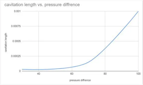
- Pressure difference vs cavitation zone length plot
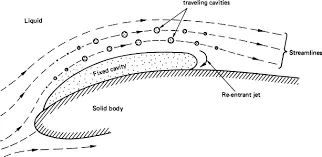
Cavitation is a phenomenon in which the reduction of pressure to or below the liquid's vapour pressure leads to the formation of small vapor-filled cavities in the liquid. When subjected to higher pressure, these cavities, called "bubbles" or "voids", collapse and can generate shock waves that may damage machinery. These shock waves are strong when they are very close to the imploded bubble, but rapidly weaken as they propagate away from the implosion.
The process in which a void or bubble in a liquid rapidly collapses, producing a shock wave, is called inertial cavitation. Inertial cavitation occurs in nature in the strikes of mantis shrimps and pistol shrimps, as well as in the vascular tissues of plants. In man-made objects, it can occur in control valves, pumps, propellers and impellers..
Since the shock waves formed by collapse of the voids are strong enough to cause significant damage to parts, cavitation is typically an undesirable phenomenon in machinery (although desirable if intentionally used, for example, to sterilize contaminated surgical instruments, break down pollutants in water purification systems, emulsify tissue for cataract surgery or kidney stone lithotripsy, or homogenize fluids). It is very often specifically avoided in the design of machines such as turbines or propellers, and eliminating cavitation is a major field in the study of fluid dynamics. However, it is sometimes useful and does not cause damage when the bubbles collapse away from machinery, such as in supercavitation.
Inertial cavitation was first observed in the late 19th century, considering the collapse of a spherical void within a liquid. When a volume of liquid is subjected to a sufficiently low pressure, it may rupture and form a cavity. This phenomenon is coined cavitation inception and may occur behind the blade of a rapidly rotating propeller or on any surface vibrating in the liquid with sufficient amplitude and acceleration. A fast-flowing river can cause cavitation on rock surfaces, particularly when there is a drop-off, such as on a waterfall.
Other ways of generating cavitation voids involve the local deposition of energy, such as an intense focused laser pulse (optic cavitation) or with an electrical discharge through a spark. Vapor gases evaporate into the cavity from the surrounding medium; thus, the cavity is not a vacuum at all, but rather a low-pressure vapor (gas) bubble. Once the conditions which caused the bubble to form are no longer present, such as when the bubble moves downstream, the surrounding liquid begins to implode due its higher pressure, building up inertia as it moves inward. As the bubble finally collapses, the inward inertia of the surrounding liquid causes a sharp increase of pressure and temperature of the vapor within. The bubble eventually collapses to a minute fraction of its original size, at which point the gas within dissipates into the surrounding liquid via a rather violent mechanism which releases a significant amount of energy in the form of an acoustic shock wave and as visible light. At the point of total collapse, the temperature of the vapor within the bubble may be several thousand kelvin, and the pressure several hundred atmospheres.
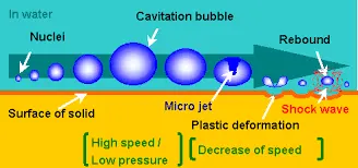
Inertial cavitation can also occur in the presence of an acoustic field. Microscopic gas bubbles that are generally present in a liquid will be forced to oscillate due to an applied acoustic field. If the acoustic intensity is sufficiently high, the bubbles will first grow in size and then rapidly collapse. Hence, inertial cavitation can occur even if the rarefaction in the liquid is insufficient for a Rayleigh-like void to occur. High-power ultrasonics usually utilize the inertial cavitation of microscopic vacuum bubbles for treatment of surfaces, liquids, and slurries.
The physical process of cavitation inception is similar to boiling. The major difference between the two is the thermodynamic paths that precede the formation of the vapor. Boiling occurs when the local temperature of the liquid reaches the saturation temperature, and further heat is supplied to allow the liquid to sufficiently phase change into a gas. Cavitation inception occurs when the local pressure falls sufficiently far below the saturated vapor pressure, a value given by the tensile strength of the liquid at a certain temperature.[2]In order for cavitation inception to occur, the cavitation "bubbles" generally need a surface on which they can nucleate. This surface can be provided by the sides of a container, by impurities in the liquid, or by small undissolved microbubbles within the liquid. It is generally accepted that hydrophobic surfaces stabilize small bubbles. These pre-existing bubbles start to grow unbounded when they are exposed to a pressure below the threshold pressure, termed Blake's threshold.
The vapor pressure here differs from the meteorological definition of vapor pressure, which describes the partial pressure of water in the atmosphere at some value less than 100% saturation. Vapor pressure as relating to cavitation refers to the vapor pressure in equilibrium conditions and can therefore be more accurately defined as the equilibrium (or saturated) vapor pressure.Non-inertial cavitation is the process in which small bubbles in a liquid are forced to oscillate in the presence of an acoustic field, when the intensity of the acoustic field is insufficient to cause total bubble collapse. This form of cavitation causes significantly less erosion than inertial cavitation, and is often used for the cleaning of delicate materials, such as silicon wafers.
CAVITATION MODELLING
Cavitation and condensation are represented using the homogeneous relaxation model , where the rate at which the instantaneous mass fraction of vapor, x, approaches its equilibrium value, 𝑥𝑥̅, is defined with the following relation,
`frac[Dx][Dt]=frac[barx-x][theta`
where θ is the relaxation time scale. In this study, cavitation and condensation are assumed to occur at equal timescales,
and are calculated as `theta=theta_oalpha^-0.54 psi^-1.76` where `theta_0` is a coefficient set to 3.84e-7, α is the total void fraction, including fuel vapor and non-condensable gases, and ψ is the non-dimensional pressure ratio
`psi=frac[p_(sat)-p][p_(crit)-p_(sat)`
To adequately represent the turbulent flow structures within the throttle, the large eddy simulation (LES) dynamic structure model is employed with a minimum grid size of 5.0 μm.
CAVITATION [PRESSURE OF 30 BAR]
Geometry
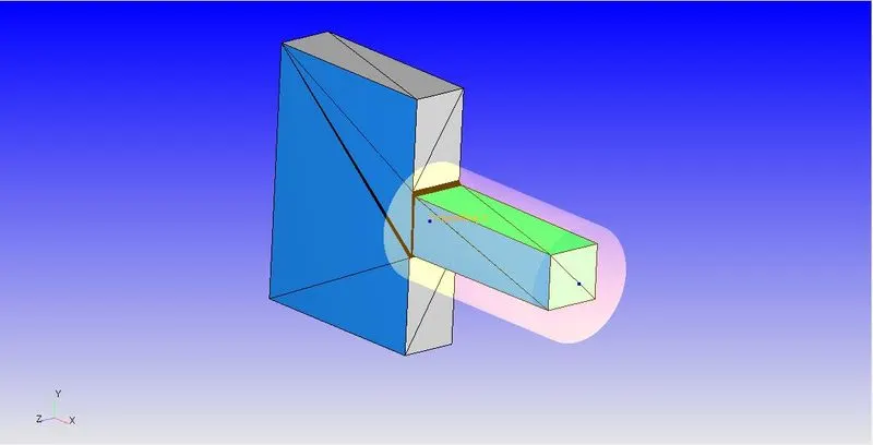
Mesh
the mesh size is 4e-5 m. the mesh generation is shown above for the AMR and fixed embedding which is applied to the geometry.
Boundary Conditions
Inlet
- inflow boundary
- pressure = 100 bar
- temperature = 300 K
- Species - tetra decane
Outlet
- outflow boundary
- pressure = 100 bar
- temperature = 300 K
- Species - tetra decane
Top and bottom walls
- wall boundary
- Temperature = 300 K
Throat
- wall boundary
- Temperature = 300 K
Results
Mass flow rate
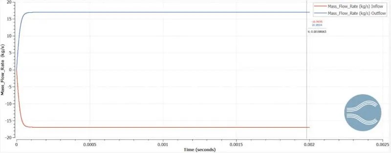
The mass flow rate has reached the convergence of 15 kg/s , which also shows the mass has converged
Velocity
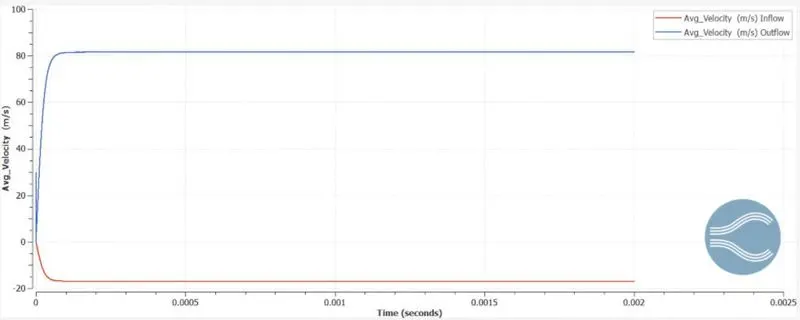
The velocity at outlet is 80 m/s and the inlet velocity is observed to be at 20m/s. there is 4 times increase in velocity s the pressure difference and the reduction in cross sectional area of nozzle.
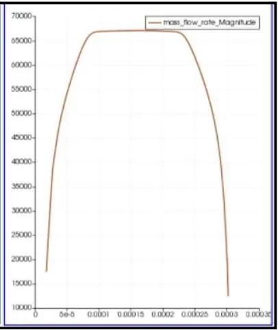
Mass flow at outlet
Animation
CAVITATION [PRESSURE OF 70 BAR]
Geometry
Mesh
the mesh size is 4e-5 m. the mesh generation is shown above for the AMR and fixed embedding which is applied to the geometry.
Boundary Conditions
Inlet
- inflow boundary
- pressure = 100 bar
- temperature = 300 K
- Species - tetra decane
Outlet
- outflow boundary
- pressure = 100 bar
- temperature = 300 K
- Species - tetra decane
Top and bottom walls
- wall boundary
- Temperature = 300 K
Throat
- wall boundary
- Temperature = 300 K
Results
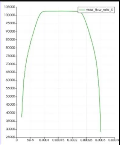
Mass flow rate
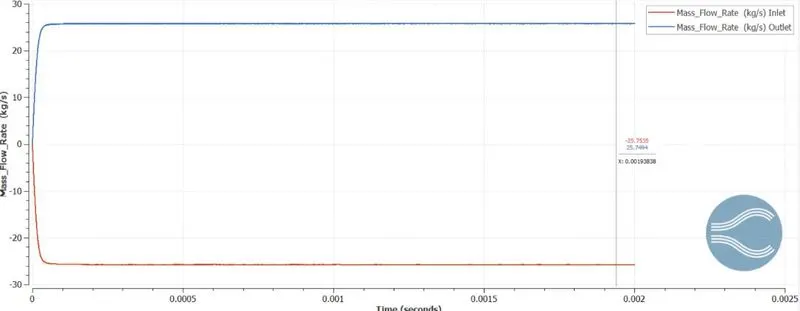
The mass flow rate has reached the convergence of 25 kg/s , which also shows the mass has converged
Velocity
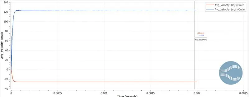
The velocity at outlet is 120 m/s and the inlet velocity is observed to be at 20m/s. there is 6 times increase in velocity s the pressure difference and the reduction in cross sectional area of nozzle.
Mass flow at outlet
Animation
CAVITATION [PRESSURE OF 100 BAR]
Geometry
Mesh
the mesh size is 4e-5 m. the mesh generation is shown above for the AMR and fixed embedding which is applied to the geometry.
Boundary Conditions
Inlet
- inflow boundary
- pressure = 100 bar
- temperature = 300 K
- Species - tetra decane
Outlet
- outflow boundary
- pressure = 100 bar
- temperature = 300 K
- Species - tetra decane
Top and bottom walls
- wall boundary
- Temperature = 300 K
Throat
- wall boundary
- Temperature = 300 K
Results
Mass flow rate
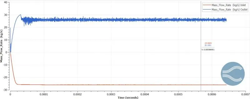
The mass flow rate has reached the convergence of 30 kg/s , which also shows the mass has converged
Velocity
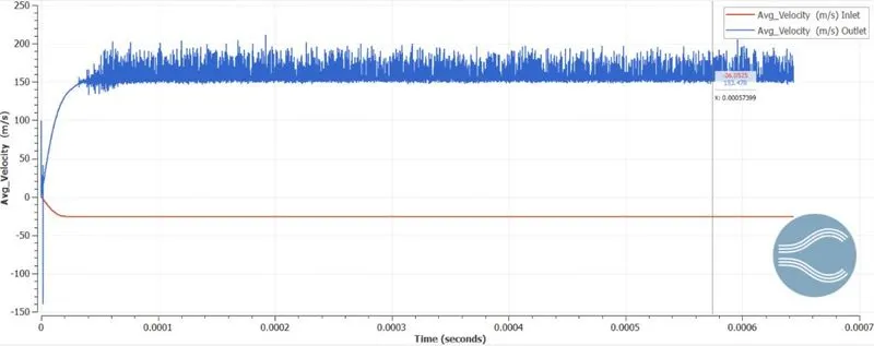
The velocity at outlet is 200 m/s and the inlet velocity is observed to be at 20m/s. there is 10 times increase in velocity s the pressure difference and the reduction in cross sectional area of nozzle.
Mass flow at outlet
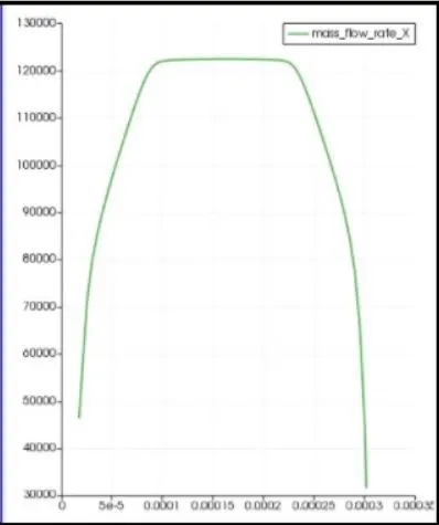
Animation
PRESURE V/S CAVITATION LENGTH
CONCLUSION
- The simualtion with different pressure conditions were done
- pressure versus cavitation length is plotted in excel