Turbocharger Modelling Using GT Suite
AIM
The aim is to analyse turbocharger modelling using GT-Suite
OBJECTIVES
The objectives of the challenge are
- Types of turbochargers and their models in GT-Suite
- Variable Geometry Turbocharger applications
- Plotting of operating points on turbine and compressor map
TURBOCHARGER
A turbocharger is a turbine-driven, forced induction device that increases an IC engine's efficiency and power output by forcing extra compressed air into the combustion chamber. This improvement over a naturally aspirated's power output is due to the fact that the compressor can force more air—and proportionately more fuel—into the combustion chamber than atmospheric pressure alone.
Turbochargers were originally known as turbosuperchargers when all forced induction devices were classified as superchargers. Today, the term "supercharger" is typically applied only to mechanically driven forced induction devices. The key difference between a turbocharger and a conventional supercharger is that a supercharger is mechanically driven by the engine, often through a belt connected to the crankshaft, whereas a turbocharger is powered by a turbine driven by the engine's exhaust gas. Compared with a mechanically driven supercharger, turbochargers tend to be more efficient, but less responsive.
TYPES OF TURBOCHARGER
- Single Turbo
- Sequential Turbo
- Twin scroll Turbo
- VGT Turbo
- Variable Twin Scroll Turbo
- Electric Turbo
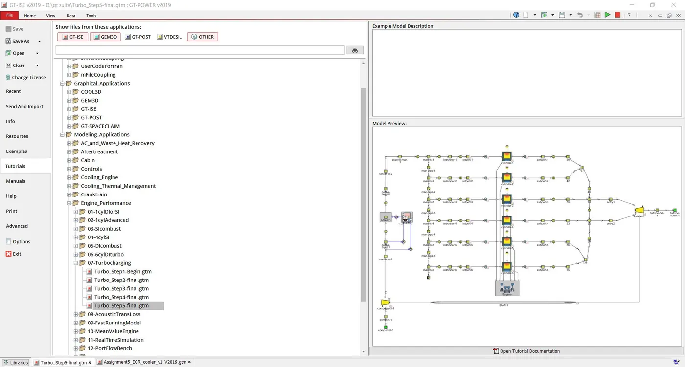
FIXED TURBOCHARGING MODEL
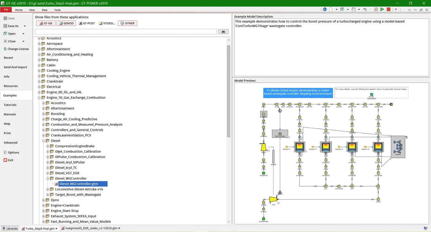
WASTE GATE TURBOCHARGING MODEL
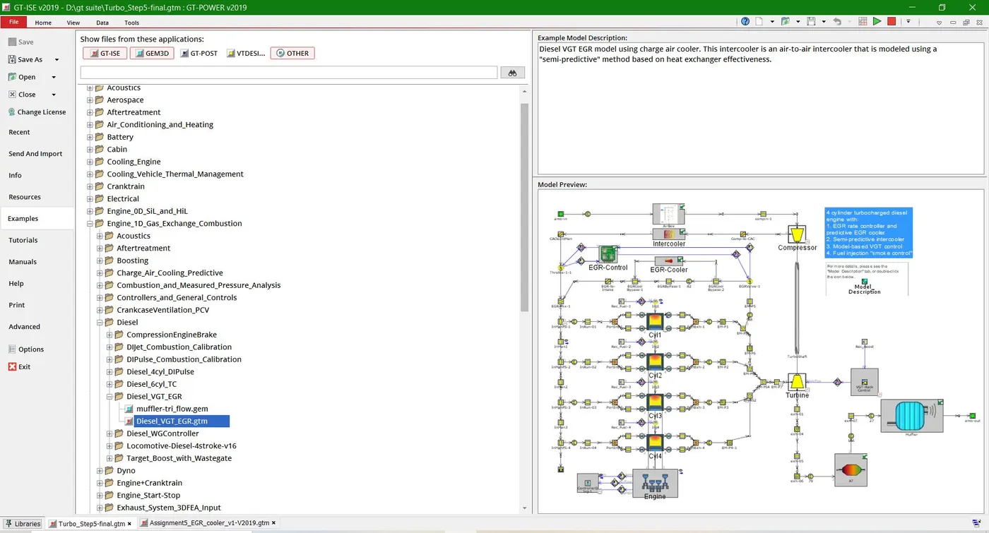
VARIABLE GEOMETRY TUROCHARGING MODEL
TUTORIAL 6 MODEL
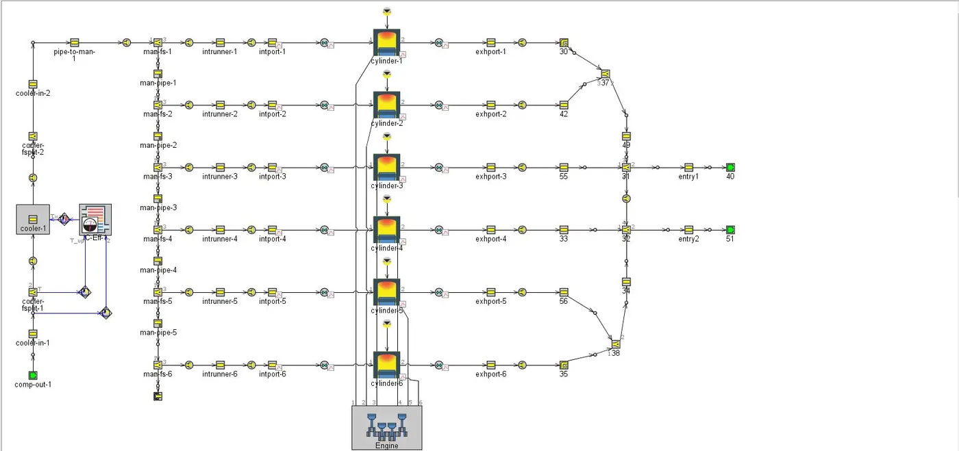
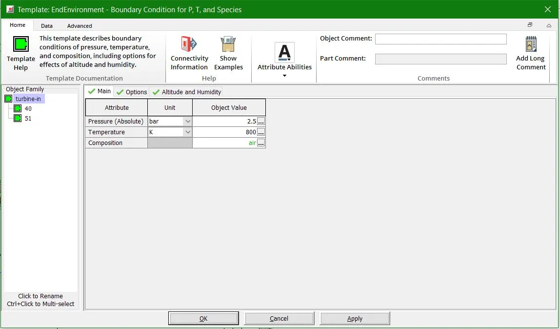
In this model the input conditions is directly coming from the compressor and they have not used the compressor template, instead while giving the ambient conditions the pressure and temperature are given of the compressor outlet. Same is done for the turbine as well, they have just given the ambient conditions for turbine.
Inlet Conditions
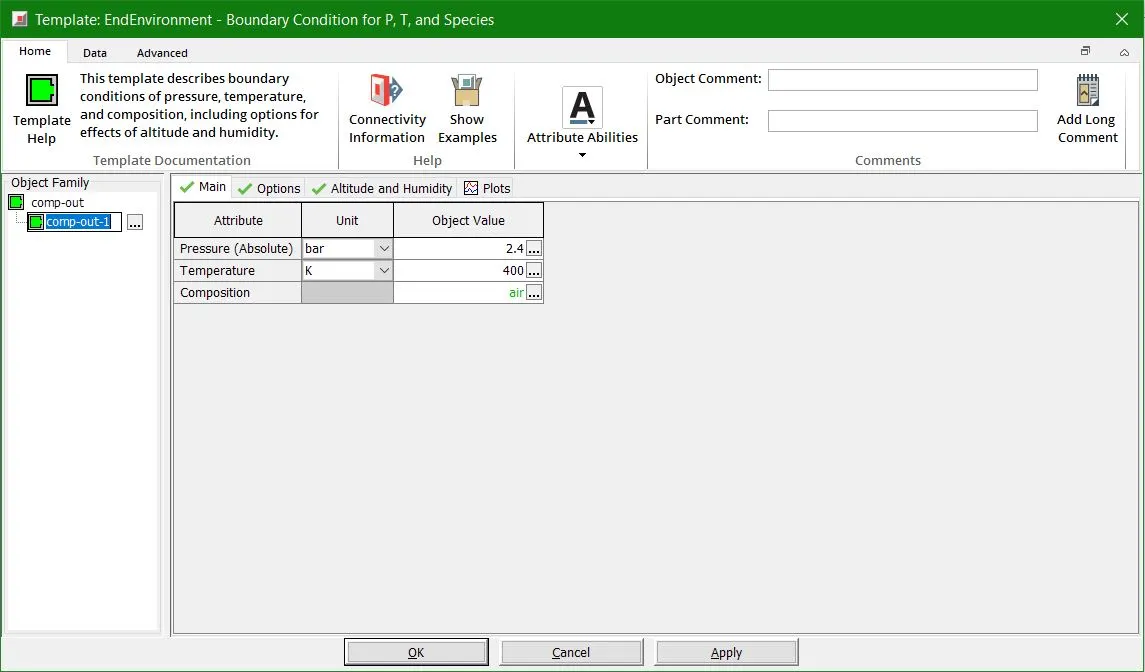
Exhaust Conditions
TUTORIAL 7 MODEL
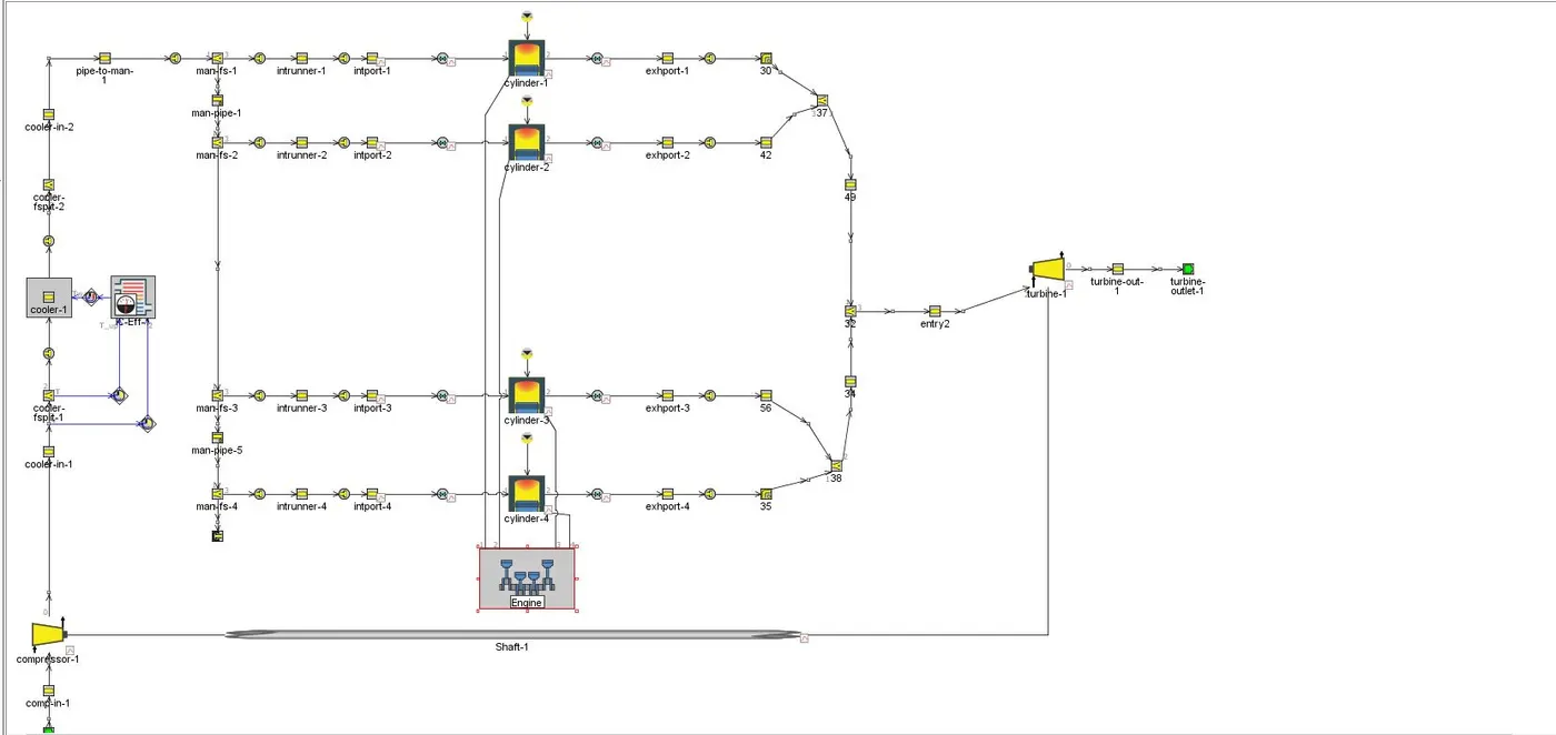
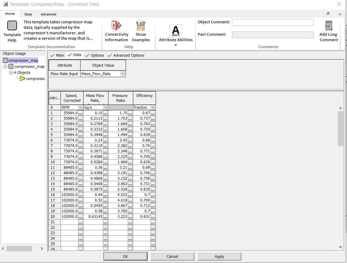
In this model the compressor and turbine templates are defined and thier respective maps are then plotted and fed into the data points as shown below
Compressor Data
Turbine Data
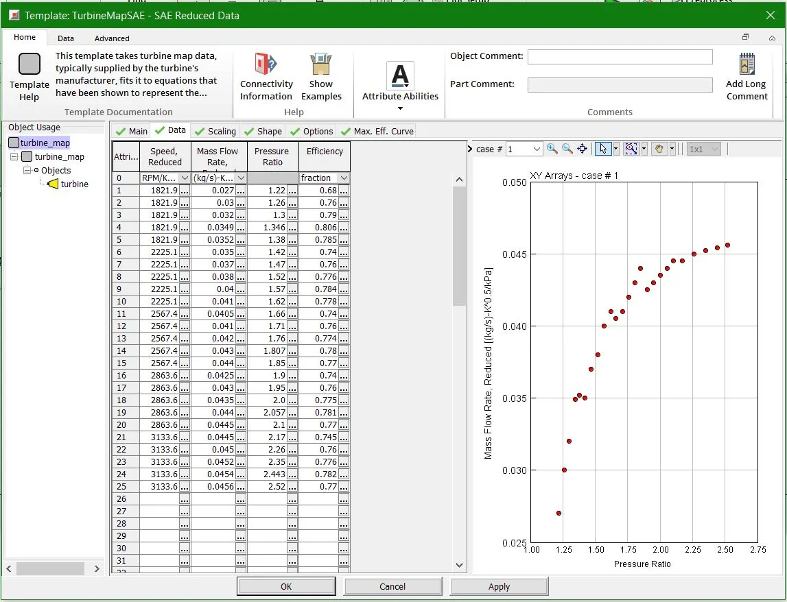
When the simulations are run we can extract the compressor and turbine maps which is shown below
COMPRESSOR AND TURBINE MAPS
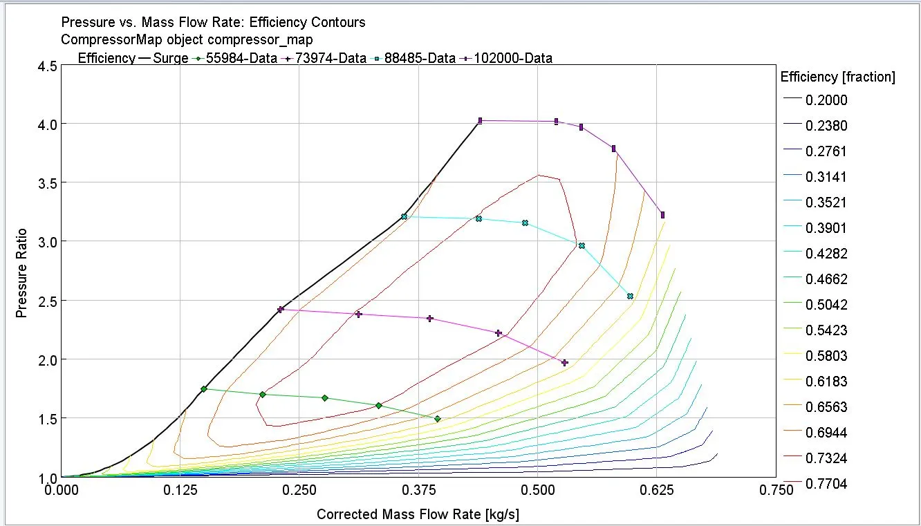
Now there are certain terms based on compressor maps which are as follows
- Flow axis - The x-axis is usually some function of compressor entry mass flow, usually corrected flow or non-dimensional flow, as opposed to real flow. This axis can be considered a rough measure of the axial Mach number of the flow through the device.
- Pressure ratio axis- Normally the y-axis is pressure ratio (Pexit/Pinlet), where P is stagnation (or total head) pressure. ΔT/T (or similar), where T is stagnation (or total head) temperature, is also used.
- Surge line- The slightly kinked diagonal line on the main (i.e. lower) part of the map is known as the surge (or stall) line. Above this line is a region of unstable flow, which is an area best avoided. A compressor surge causes an abrupt reversal of airflow throughout the unit. Compressor blades create a pumping action by working as airfoils.
- Speed lines- The slightly curved, near vertical, lines on the main part of the map are the (constant rotational) corrected speed lines. They are a measure of rotor blade tip mach number. Note on the illustration that the speed lines are not distributed linearly with flow. This is because this particular compressor is fitted with variable stators, which open progressively as speed increases, causing an exaggerated increase in flow in the medium to high speed region. At low speed, the variable stators are locked, causing a more linear relationship between speed and flow.
- Efficiency axis- A sub-plot shows the variation of isentropic efficiency with flow, at constant speed. Some maps use polytropic efficiency. Alternatively, for illustrative purposes, efficiency contours are sometimes cross-plotted onto the main map. Note that the locus of peak efficiency exhibits a slight kink in its upward trend. This is due to the choking-up of the compressor as speed increases, with the variable stators closed-off. The trend line resumes once the variables start to move open.
- Working line- Also shown on the map is a typical steady state working (or operating/running) line. This is a locus of the operating points of the engine, as it is throttled.being a high pressure ratio device, the working line is relatively shallow. If the unit had no variable geometry, there would be handling problems, because the surge line would be very steep and cross the working line at part-flow.
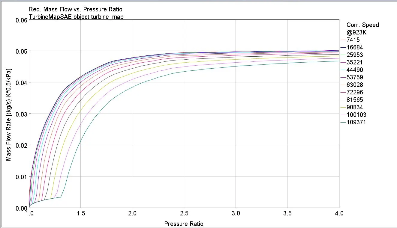
A typical turbine map is shown on the top.The y-axis is some measure of flow, usually non-dimensional flow or, as in this case corrected flow, but not actual flow. Sometimes the axes of a turbine map are transposed, to be consistent with those of a compressor map. As in this case, a companion plot, showing the variation of isentropic or polytropic efficiency, is often also included.
Unlike a compressor (or fan), surge (or stall) does not occur in a turbine. This is because the flow through the unit is all 'downhill', from high to low pressure. Consequently there is no surge line marked on a turbine map. Working lines are difficult to see on a conventional turbine map because the speed lines bunch up. One trick is to replot the map, with the y-axis being the multiple of flow and corrected speed. This separates the speed lines, enabling working lines (and efficiency contours) to be cross-plotted and clearly seen.
VGT TURBOCHARGING MODEL
VGT TEMPLATE
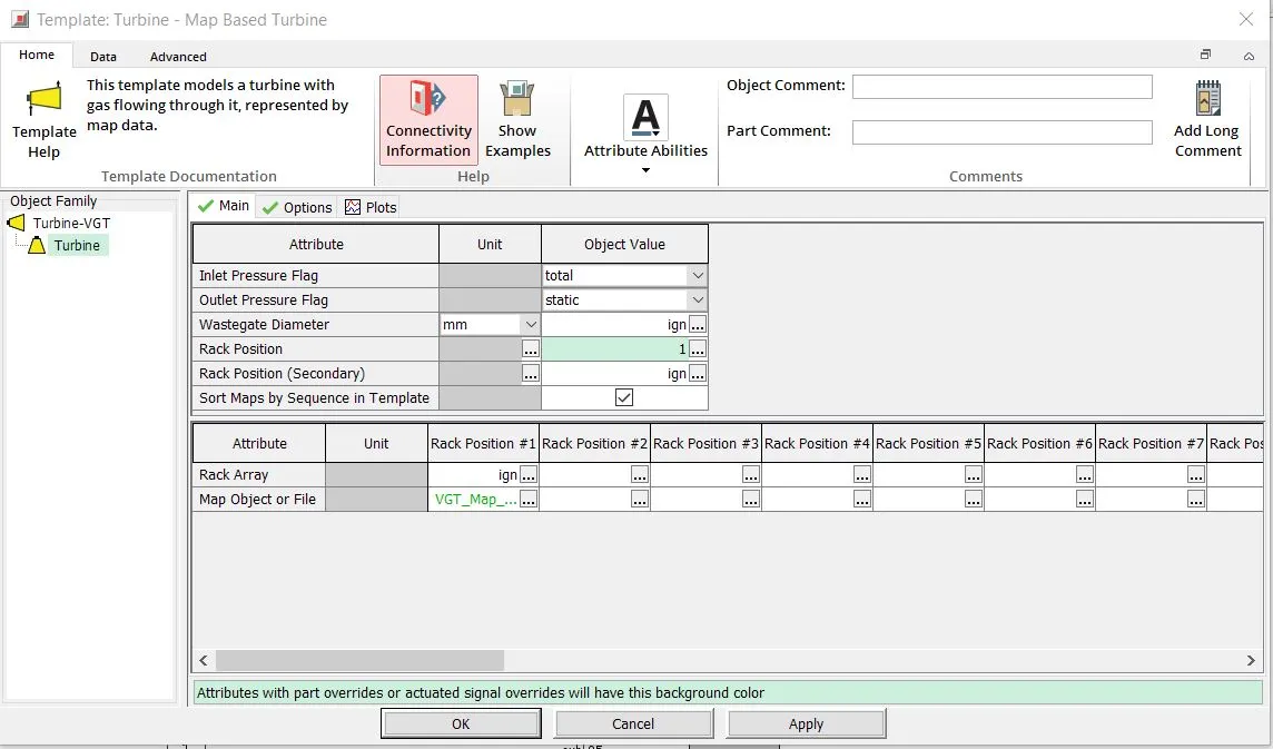
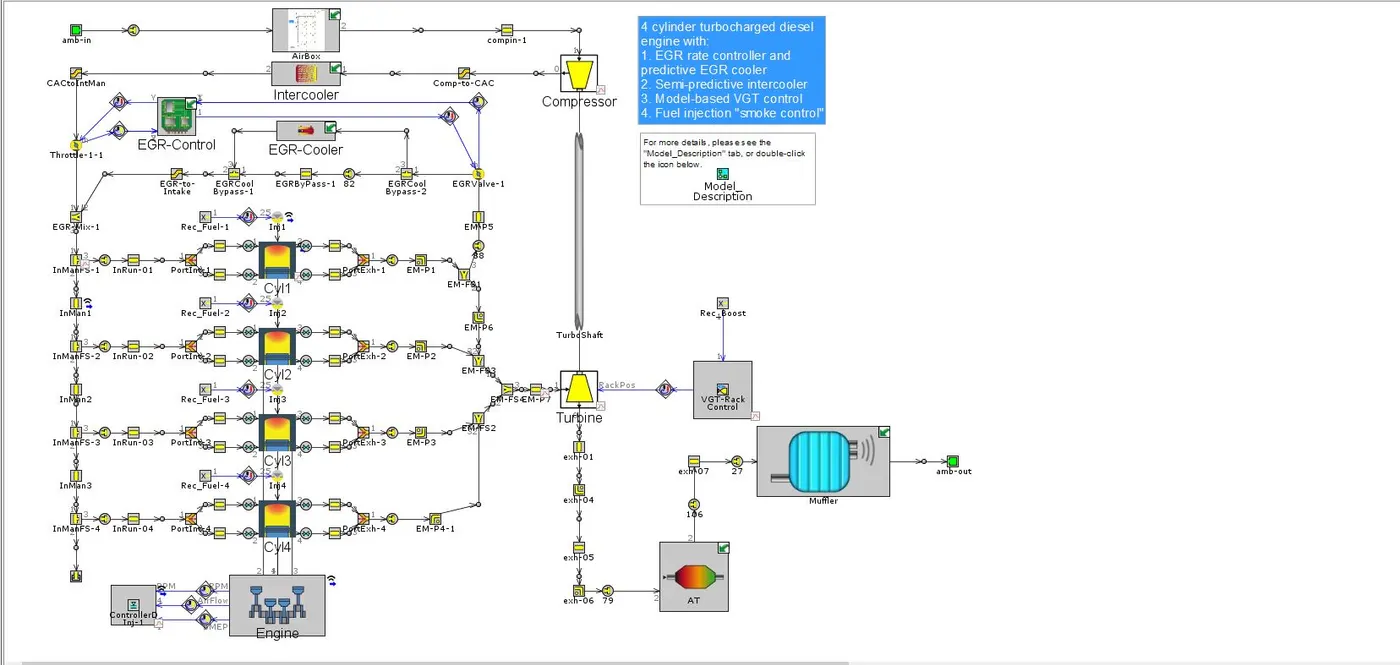
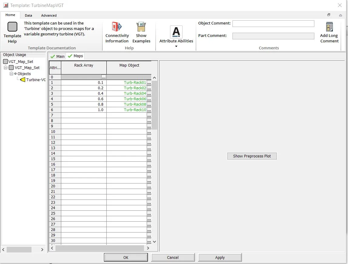
Here there are multiple rack positions in which we can either define multiple rack positions or feed them with various turbine maps.
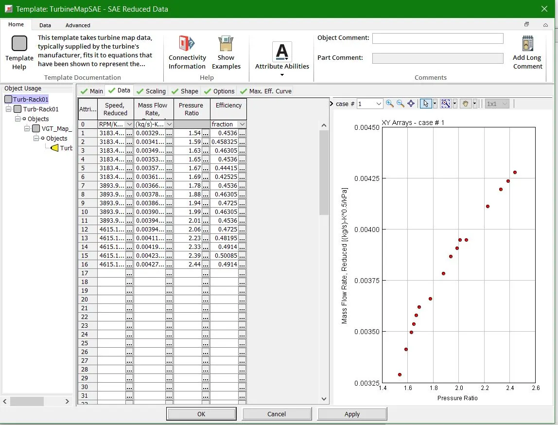
There are 4 parameters which we define such as the speed, mass flow rate, pressure ratio and efficiency for various engine speeds for the turbine map
VARIABLE GEOMETRY TURBOCAHRGER APPLICATIONS
VGTs tend to be much more common on diesel engines, as lower exhaust temperatures mean they are less prone to failure. Early gasoline-engine VGTs required significant pre-charge cooling to extend the turbocharger life to reasonable levels, but advances in technology have improved their resistance to high-temperature gasoline exhaust, and they have started to appear increasingly in gasoline-engined cars.
Typically, VGTs are only found in OEM applications due to the level of coordination required to keep the vanes in the most optimal position for whatever state the engine is in. However, there are aftermarket VGT control units available, and some high-end aftermarket engine management systems can control VGTs as well.
In trucks, VGTs are also used to control the ratio of exhaust recirculated back to the engine inlet (they can be controlled to selectively increase the exhaust manifold pressure until it exceeds the inlet manifold pressure, which promotes exhaust gas recirculation). Although excessive engine back pressure is detrimental to overall fuel efficiency, ensuring a sufficient EGR rate even during transient events (such as gear changes) can be sufficient to reduce nitrogen oxide emissions down to that required by emissions legislation (e.g., Euro 5 for Europe and EPA 10 for the USA).
Another use for sliding-vane turbochargers is as a downstream exhaust brake, so that an extra exhaust throttle valve is not needed. The mechanism can also be deliberately modified to reduce the turbine efficiency in a pre-defined position. This mode can be selected to sustain a raised exhaust temperature to promote "light-off" and "regeneration" of a diesel particulate filter. Actuation of a VGT for EGR flow control, or to implement braking or regeneration modes in general, requires hydraulic actuators or electric servos.
CONCLUSION
- Different turbochargers modelling approaches were explored on GT-Suite
- Compressor and Turbine maps are defined
- The benefits of VGT are also explored