Turbo Charger Simulation Project
AIM
The aim of this project is to simulate the turbocharger flow analysis
OBJECTIVES
- Pressure ratios of different conditions
- Speed of impeller
- FSI model for turbocharger
TURBOCHARGER
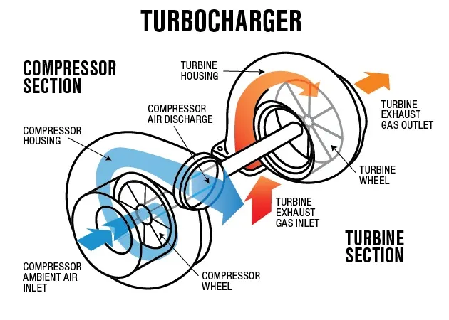
A turbocharger, colloquially known as a turbo, is a turbine-driven, forced induction device that increases an internal combustion engine's power output by forcing extra compressed air into the combustion chamber.This improvement over a naturally aspirated engine's power output is because the compressor can force more air—and proportionately more fuel—into the combustion chamber than atmospheric pressure (and for that matter, ram air intakes) alone.
In naturally aspirated piston engines, intake gases are drawn or "pushed" into the engine by atmospheric pressure filling the volumetric void caused by the downward stroke of the piston (which creates a low-pressure area), similar to drawing liquid using a syringe. The amount of air actually drawn in, compared with the theoretical amount if the engine could maintain atmospheric pressure, is called volumetric efficiency. The objective of a turbocharger is to improve an engine's volumetric efficiency by increasing density of the intake gas (usually air) allowing more power per engine cycle.
The turbocharger's compressor draws in ambient air and compresses it before it enters into the intake manifold at increased pressure. This results in a greater mass of air entering the cylinders on each intake stroke. The power needed to spin the centrifugal compressor is derived from the kinetic energy of the engine's exhaust gases.
In automotive applications, 'boost' refers to the amount by which intake manifold pressure exceeds atmospheric pressure at sea level. This is representative of the extra air pressure that is achieved over what would be achieved without the forced induction. The level of boost may be shown on a pressure gauge, usually in bar, psi or possibly kPa. The control of turbocharger boost has changed dramatically over the 100-plus years of their use. Modern turbochargers can use wastegates, blow-off valves and variable geometry, as discussed in later sections.
In petrol engine turbocharger applications, boost pressure is limited to keep the entire engine system, including the turbocharger, inside its thermal and mechanical design operating range. Over-boosting an engine frequently causes damage to the engine in a variety of ways including pre-ignition, overheating, and over-stressing the engine's internal hardware. For example, to avoid engine knocking (also known as detonation) and the related physical damage to the engine, the intake manifold pressure must not get too high, thus the pressure at the intake manifold of the engine must be controlled by some means. Opening the wastegate allows the excess energy destined for the turbine to bypass it and pass directly to the exhaust pipe, thus reducing boost pressure. The wastegate can be either controlled manually (frequently seen in aircraft) or by an actuator (in automotive applications, it is often controlled by the engine control unit).
Pressure increase (or boost)[edit]
A turbocharger may also be used to increase fuel efficiency without increasing power. This is achieved by diverting exhaust waste energy, from the combustion process, and feeding it back into the turbo's "hot" intake side that spins the turbine. As the hot turbine side is being driven by the exhaust energy, the cold intake turbine (the other side of the turbo) compresses fresh intake air and drives it into the engine's intake. By using this otherwise wasted energy to increase the mass of air, it becomes easier to ensure that all fuel is burned before being vented at the start of the exhaust stage. The increased temperature from the higher pressure gives a higher Carnot efficiency.
A reduced density of intake air is caused by the loss of atmospheric density seen with elevated altitudes. Thus, a natural use of the turbocharger is with aircraft engines. As an aircraft climbs to higher altitudes, the pressure of the surrounding air quickly falls off. At 18,000 feet (5,500 m), the air is at half the pressure of sea level, which means that the engine produces less than half-power at this altitude.In aircraft engines, turbocharging is commonly used to maintain manifold pressure as altitude increases (i.e. to compensate for lower-density air at higher altitudes). Since atmospheric pressure reduces as the aircraft climbs, power drops as a function of altitude in normally aspirated engines. Systems that use a turbocharger to maintain an engine's sea-level power output are called turbo-normalized systems. Generally, a turbo-normalized system attempts to maintain a manifold pressure of 29.5 inHg (100 kPa).
TURBOCHARGER SIMULATION[ PRESSURE RATIO 2 ]
Geometry
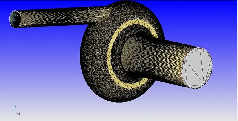
Mesh
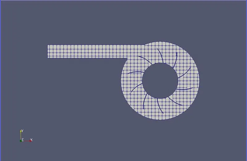
For the turbocharger simulation to run, we have used the default size of 0.004m cells
Boundary Conditions
Inlet
- Inflow Boundary
- Pressure = 2 bar
- Temperature = 800 K
- Species - Air
Outlet
- Outflow Boundary
- Pressure = 1 bar
- Temperature = 450 K
- Species - Air
Casing
- Wall Boundary
- Wall motion - fixed
- Temperature = 450 K
Turbine Wheel
- Wall Boundary
- Wall motion - fixed
- Temperature = 450 K
Results
Mass Flow Rate
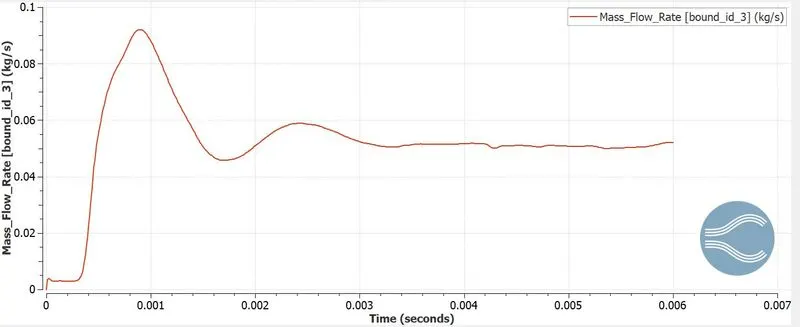
Now the mass flow rate has converged at 0.05 kg/s, the negative sign indicates that the flow is in the opposite direction of that of inlet flow.
Pressure
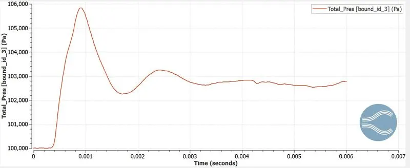
Pressure has taken a value of 103000 pascals at the outlet.
Velocity
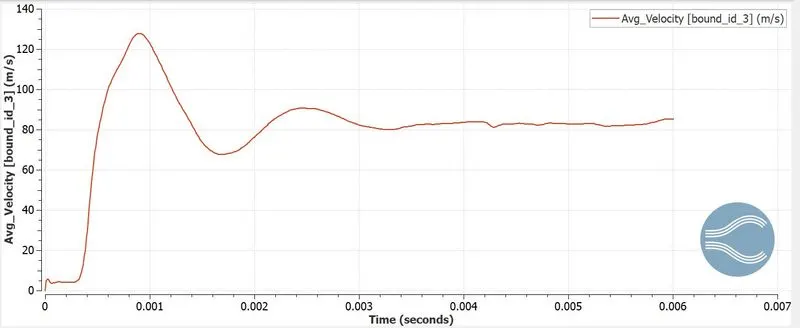
The linear speed of air has reached a convergence of 85 m/s at the outlet
Rotational velocity
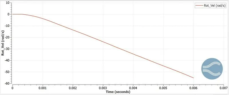
The rotational speed attained by the turbine impeller due to FSI is 55 rad/sec
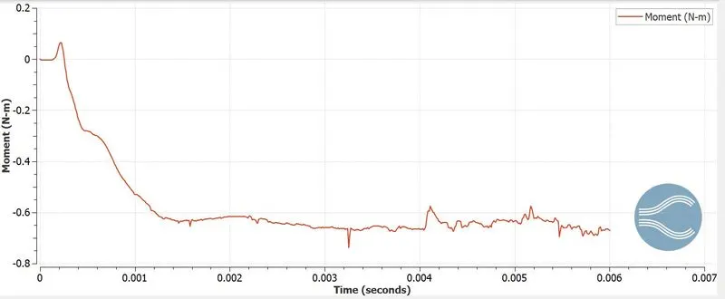
Torque
Cell Count
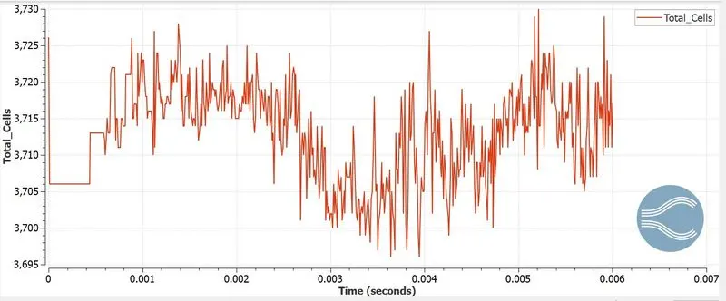
The total number of cell count has gone upto 3730 cells.
Animation Files
Pressure Contour
Velocity Contour
TURBOCHARGER SIMULATION[ PRESSURE RATIO 2.5]
Geometry
Mesh
For the turbocharger simulation to run, we have used the default size of 0.004m cells
Boundary Conditions
Inlet
- Inflow Boundary
- Pressure = 2.5 bar
- Temperature = 800 K
- Species - Air
Outlet
- Outflow Boundary
- Pressure = 1 bar
- Temperature = 450 K
- Species - Air
Casing
- Wall Boundary
- Wall motion - fixed
- Temperature = 450 K
Turbine Wheel
- Wall Boundary
- Wall motion - fixed
- Temperature = 450 K
Results
Mass Flow Rate
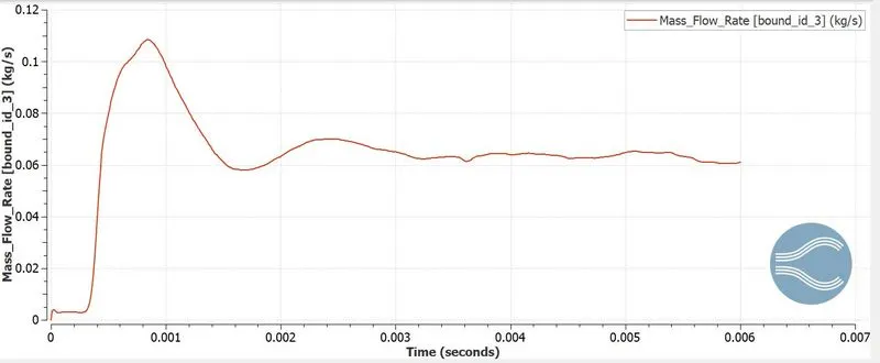
Now the mass flow rate has converged at 0.06 kg/s, the negative sign indicates that the flow is in the opposite direction of that of inlet flow.
Pressure
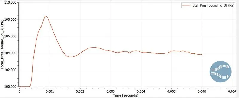
Pressure has taken a value of 104000 pascals at the outlet.
Velocity
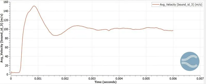
The linear speed of air has reached a convergence of 100 m/s at the outlet
Rotational velocity
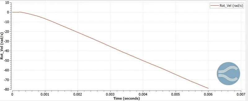
The rotational speed attained by the turbine impeller due to FSI is 80 rad/sec
Torque
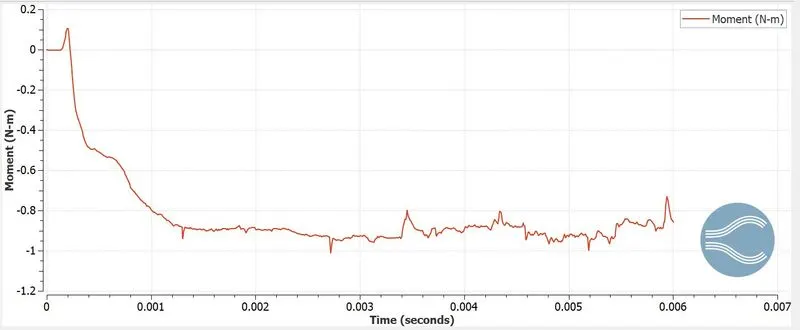
Cell Count
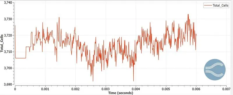
The total number of cell count has gone upto 3730 cells.
Animation Files
Pressure Contour
Velocity Contour
TURBOCHARGER SIMULATION [ PRESSURE RATIO - 3 ]
Geometry
Mesh
For the turbocharger simulation to run, we have used the default size of 0.004m cells
Boundary Conditions
Inlet
- Inflow Boundary
- Pressure = 3 bar
- Temperature = 800 K
- Species - Air
Outlet
- Outflow Boundary
- Pressure = 1 bar
- Temperature = 450 K
- Species - Air
Casing
- Wall Boundary
- Wall motion - fixed
- Temperature = 450 K
Turbine Wheel
- Wall Boundary
- Wall motion - fixed
- Temperature = 450 K
Results
Mass Flow Rate
Now the mass flow rate has converged at 0.07 kg/s, the negative sign indicates that the flow is in the opposite direction of that of inlet flow.
Pressure
Pressure has taken a value of 104000 pascals at the outlet.
Velocity
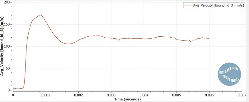
The linear speed of air has reached a convergence of 120 m/s at the outlet
Rotational velocity
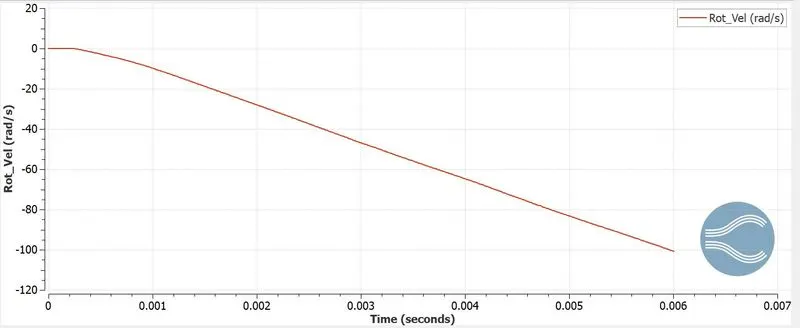
The rotational speed attained by the turbine impeller due to FSI is 100 rad/sec
Torque
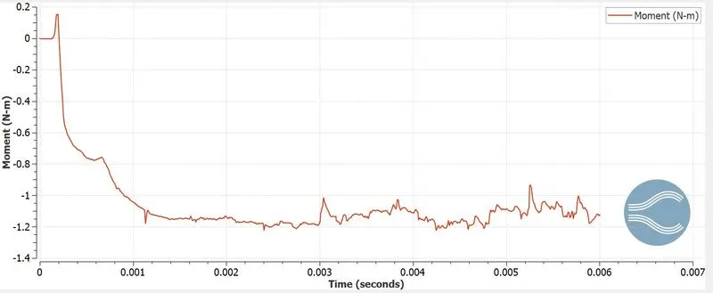
Cell Count
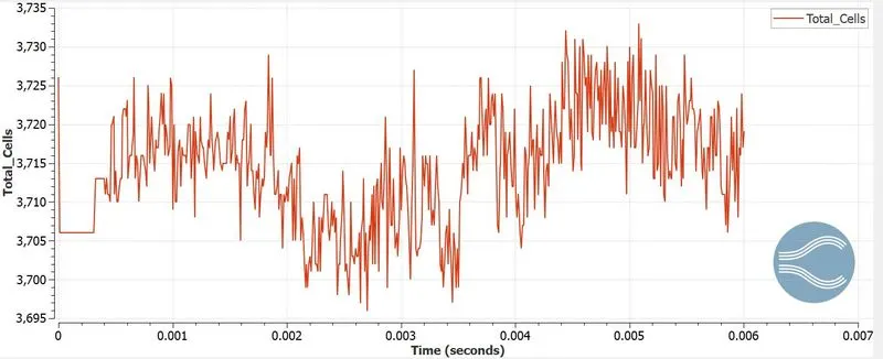
The total number of cell count has gone upto 3730 cells.
Animation Files
Pressure Contour
Velocity Contour
Fluid Structure Interaction
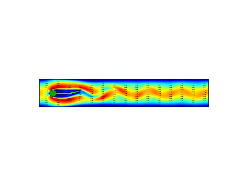
Fluid-structure interaction (FSI) is a multiphysics coupling between the laws that describe fluid dynamics and structural mechanics. This phenomenon is characterized by interactions – which can be stable or oscillatory – between a deformable or moving structure and a surrounding or internal fluid flow.When a fluid flow encounters a structure, stresses and strains are exerted on the solid object – forces that can lead to deformations. These deformations can be quite large or very small, depending on the pressure and velocity of the flow and the material properties of the actual structure.
If the deformations of the structure are quite small and the variations in time are also relatively slow, the fluid's behavior will not be greatly affected by the deformation, and we can concern ourselves with only the resultant stresses in the solid parts. However, if the variations in time are fast, greater than a few cycles per second, then even small structural deformations will lead to pressure waves in the fluid. These pressure waves lead to the radiation of sound from vibrating structures. Such problems can be treated as an acoustic-structure interaction, rather than a fluid-structure interaction.
Yet, if the deformations of the structure are large, the velocity and pressure fields of the fluid will change as a result, and we need to treat the problem as a bidirectionally coupled multiphysics analysis: The fluid flow and pressure fields affect the structural deformations, and the structural deformations affect the flow and pressure.
SPEED OF IMPELLER
| Pressure Ratio | Impeller Speed (rad/sec) | Impeller Speed (rpm) |
| 2 | 55 | 526 |
| 2.5 | 80 | 765 |
| 3 | 100 | 955 |
CONCLUSION
- The simulation was run with different pressure ratios
- Speed of impeller is captured in all cases
- FSI model was used in the simulation