SI Engine Power Increasing simulation
AIM
The aim of the challenge is to run the simulation on SI Engine
OBJECTIVES
The objectives of this simulation are
- Running the simulation for engine speed of 1800 rpm
- Increase the power output by 10 % while engine is running at 3600 rpm
ENGINE PARAMETERS
Air Flow Rate
The air flow rate is defined as mass of air that is entering the engine cylinder during the suction stroke of the engine.
Mean Effective Pressure
The mean effective pressure is a quantity relating to the operation of a reciprocating engine and is a valuable measure of an engine's capacity to do work that is independent of engine displacement
Brake Specific Fuel Consumption
Brake-specific fuel consumption (BSFC) is a measure of the fuel efficiency of any prime mover that burns fuel and produces rotational, or shaft power. It is typically used for comparing the efficiency of internal combustion engine with a shaft output. It is the rate of fuel consumption divided by the power produced. It may also be thought of as power specific fuel consumption, for this reason. BSFC allows the fuel efficiency of different engines to be directly compared.
In cylinder Pressure
Cylinder Pressure is the pressure in the engine cylinder during the 4 strokes of engine operation (intake, compression, combustion and expansion, and exhaust).
SI ENGINE SIMULATION(1800 RPM)
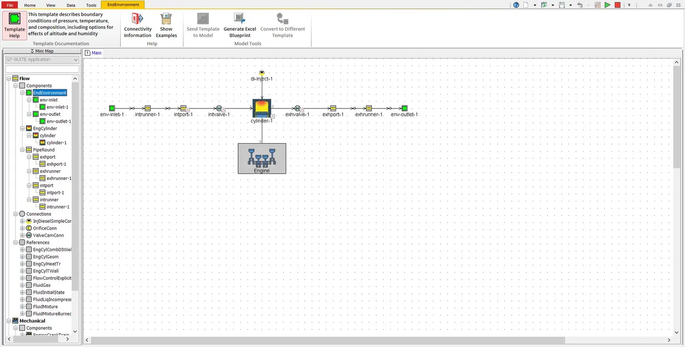
The model of the single cylinder direct injection engine model is as shown in the above image
Case Setup
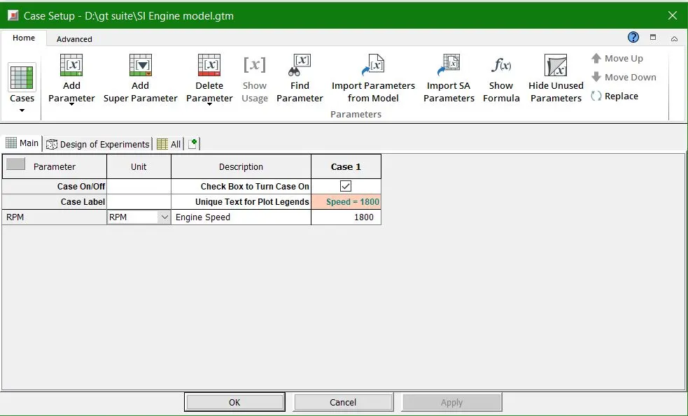
The case setup for the simulation is shown that the operating speed of the engine is 1800 rpm
Run Setup
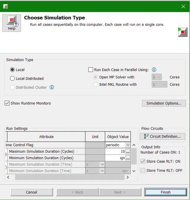
In this case the simulation was run for 10 cycles
Results
Air Flow Rate
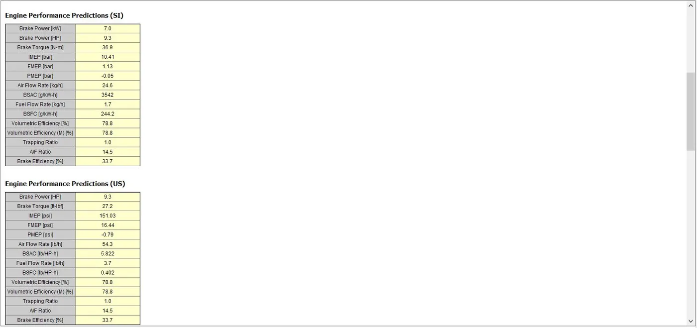
When we observe the engine performance predictions in SI, he air flow rate is found to be 24.6 kg/hour
Brake Mean Effective Pressure
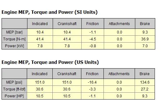
In the SI units system, the brake mean effective pressure is 9.3 bar i.e. BMEP = 9.3 bar
Brake Specific Fuel Consumption
The Brake Specific Fuel Consumption for the engine is BSFC = 244.2 g/KW-hr
In-Cylinder Pressure
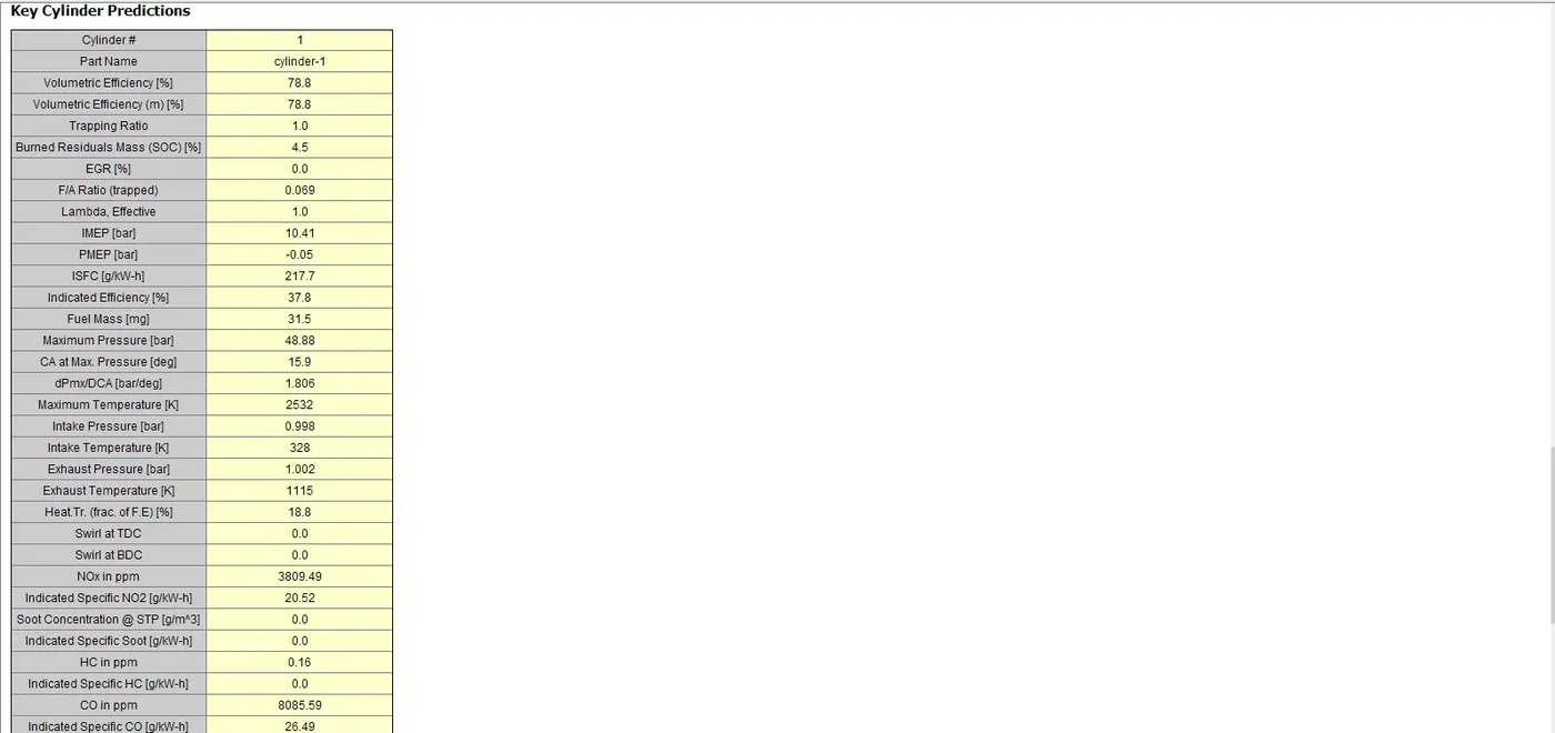
Maximum Cylinder pressure is given by 48.88 bar.
SI ENGINE SIMULATION(3600 RPM)
Case Setup
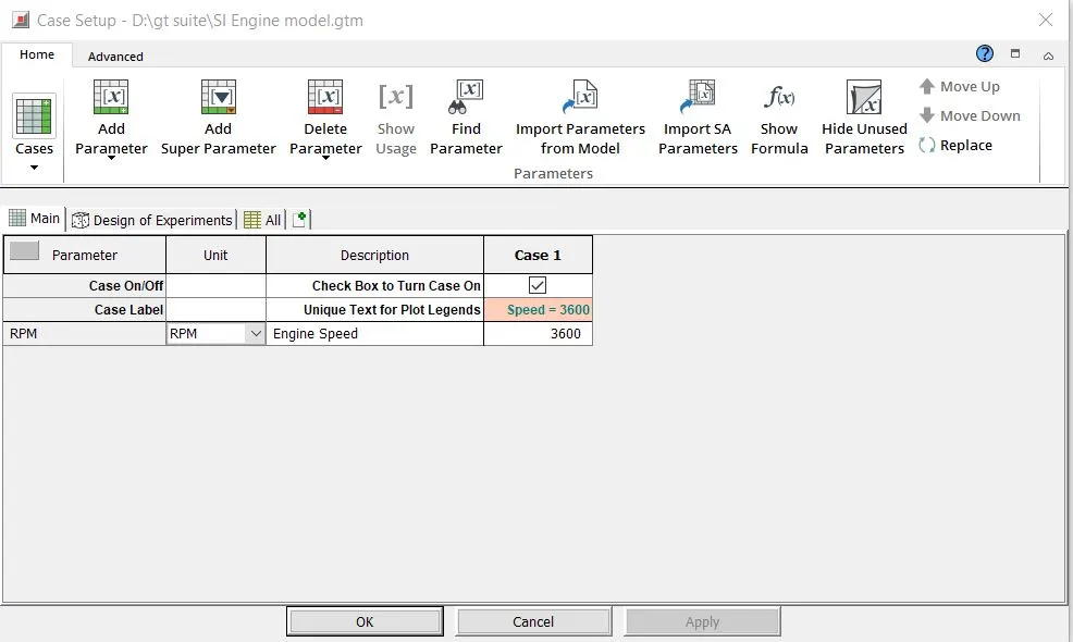
Run Setup
In this case the simulation was run for 10 cycles.
Power Output
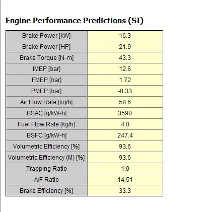
The results table shows us that the engine now develops 16.3 KW
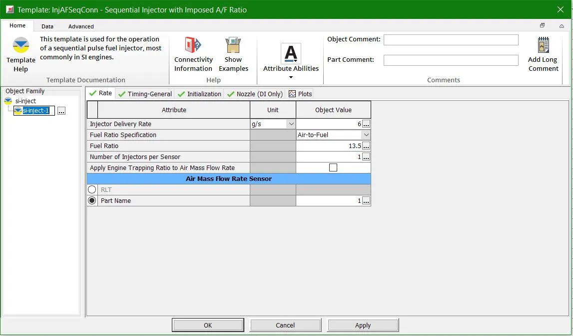
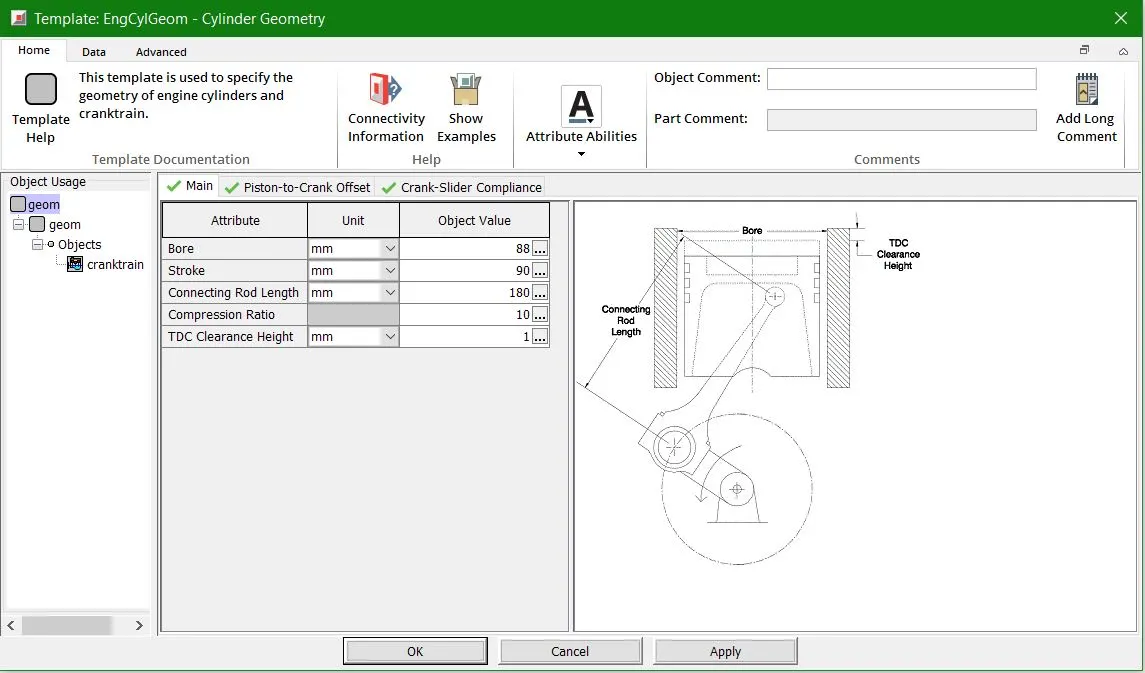
From the following images it may be seen that the engine parameters were changed
- The A/F ratio was changed from 14.5 to 13.5
- The bore diameter was changed from 86mm to 88mm
- The stroke length of the engine was changed from 86.1mm to 90 mm
- The connecting rod length was changed from 175 mm to 180 mm
- The Compression ratio was changed from 9.5 to 10
Power Output Increase
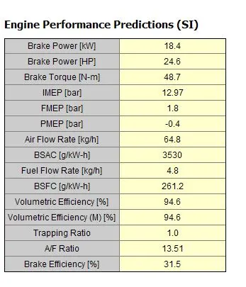
Now we can see that the power has increased from 16.3 KW to 18.4 KW which has increased by around 12%
CONCLUSION
- Raise in compression ratio increases the power output of the engine
- Rich mixture causes to increase the power but also increases the emissions from the engine.
- Various Engine parameters were studied from this simulation
- The air required to burn the fuel can be improved by changing cylinder dimensions and also note by increasing the connecting rod length improves the torque generated at crankshaft