CI engine Simulation
AIM
The aim of this simulation is to explore the CI engine model
OBJECTIVES
The objectives of the simulations are
- Comparison of SI & CI engine
- Performance parameters changes
- Effect of MFB 50 on engine performance
COMPARISION OF SI AND CI ENGINE
| SI Engine | CI Engine |
|---|---|
| It works on OTTO Cycle or constant volume heat addition. | It works on DIESEL Cycle or constant pressure heat addition. |
| During the intake or suction process, air and fuel are used. | During the intake or suction process, only air used. |
| The fuel used Petrol which is highly volatile. Self Ignition temperature is high. | The fuel used Diesel which is low volatile. Self-ignition temperature is low. |
| The fuel is supplied by Carburetor. | The fuel is supplied by Injector. |
| High speed because due to lightweight and homogeneous combustion. | Comparatively low speed because due to heavyweight and heterogeneous combustion. |
| It is used in Small Vehicles. | It is used in Heavy Vehicles. |
| The compression ratio is 6 to 10. The upper limit is fixed by the antiknock quality of the fuel. | The Compression ratio is 16 to 20. The upper limit is limited by the weight increase of the engine. |
| The stating of this engine is easy. | Starting is a little difficult comparatively SI engine. |
| Due to lower peak pressure, this is having lighter weight. | Due to higher peak pressure, this is having a Heavier weight. |
| The maintenance cost is low. | The maintenance cost is high. |
| Engine cost is less. | Engine cost is high. |
| Less production of hydrocarbon. | In this high production of hydrocarbon. |
| Less noise produces. | It produces high noise. |
| Lower thermal efficiency because of the low compression ratio. | High thermal efficiency because of the high compression ratio. |
CI ENGINE MODEL

The engine model of single cylinder CI engine is as shown in the above image
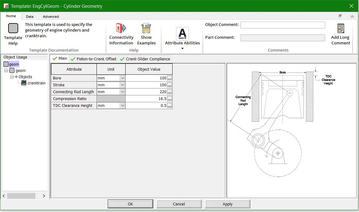
When the compression ratio is more than 15, this indicates that the engine works on Compression Ignition principle
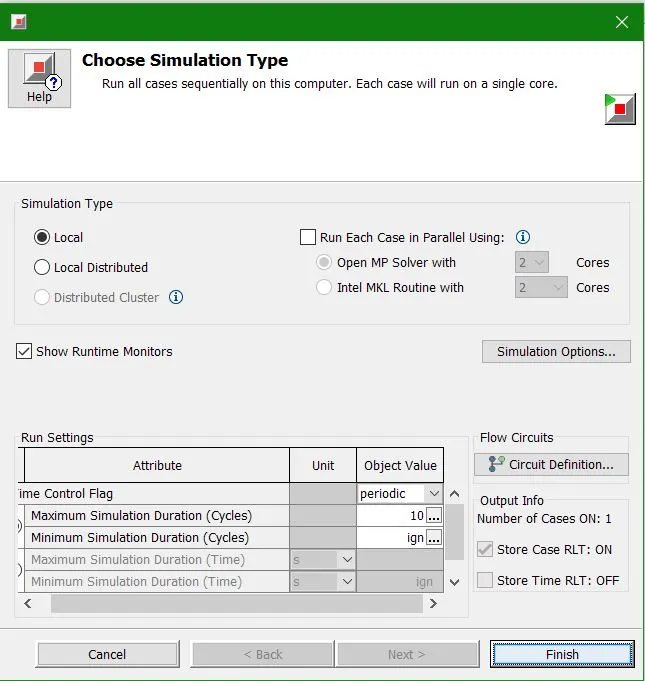
The simulation was run at 3600 rpm for 10 cycles and the results obtained
CI Engine Performance
Brake Specific Fuel Consumption
Brake-specific fuel consumption (BSFC) is a measure of the fuel efficiency of any prime mover that burns fuel and produces rotational, or shaft power. It is typically used for comparing the efficiency of internal combustion engine with a shaft output. It is the rate of fuel consumption divided by the power produced. It may also be thought of as power- specific fuel consumption, for this reason. BSFC allows the fuel efficiency of different engines to be directly compared.
BSFC is given by
`BSFC=frac[r][p]`
where:
- r is the fuel consumption rate in grams per second (g/s)
- P is the power produced in watts
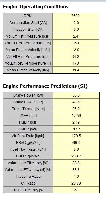
In this case of the CI engine, the BSFC = 238.2 kg/KW-hr. The BSFC is main criteria to decide the fuel efficiency.
Exhaust Temperature
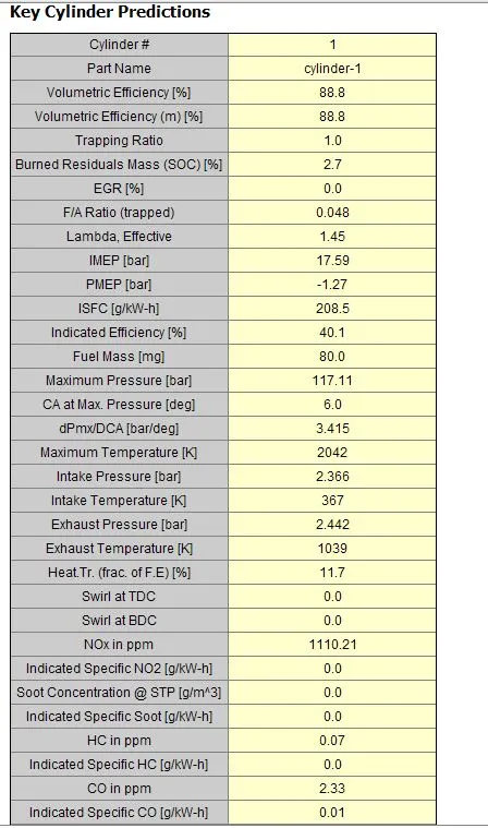
The exhaust temperature in CI engine is very high, where the temperature has reached 1039 K
A/F Ratio
Air–fuel ratio (AFR) is the mass ratio of air to a solid, liquid, or gaseous fuel present in a combustion process. The combustion may take place in a controlled manner such as in an IC engine or industrial furnace, or may result in an explosion.The air-fuel ratio determines whether a mixture is combustible at all, how much energy is being released, and how much unwanted pollutants are produced in the reaction. Typically a range of fuel to air ratios exists, outside of which ignition will not occur. These are known as the lower and upper explosive limits.
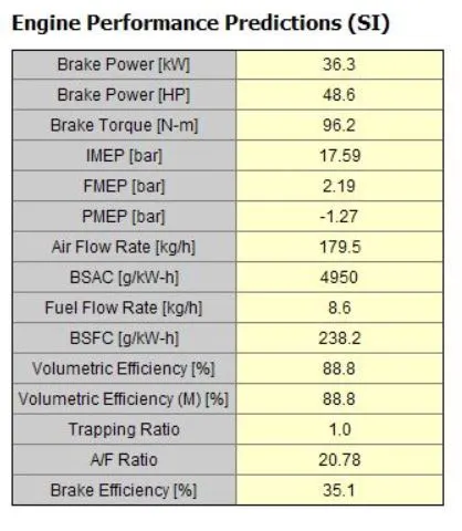
Usually the stoichometric A/F ratio is 14.5 but here the A/F ratio is 20.78 which is the reason of the high cetane number.
EFFECT OF MFB 50 ON ENGINE PERFORMANCE
Combustion phase variations in diesel engines due to production tolerance, engine, aging, and different combustion conditions cause performance deterioration of fuel economy, torque, and emissions. Therefore, the combustion phase should be controlled by feedback information. A well-known method to control the combustion phase in mass fraction burnt 50% (MFB50) control using in cylinder pressure. MFB50 control can retain performance through combustion conditions. However, MFB50 can compensate only for variations caused by combustion phase changes therefore, further study is required to supplement the limitation of MFB50 control. In this study, to analyse the effect of MFB50 control on combustion, MFB50 is controlled by adjusting the main injection timing using in-cylinder pressure at 3600 rpm and a BMEP of four bar according to engine parameter changes. The parameters are fuel rail pressure, boost pressure, mass air flow, swirl valve open, main injection quantity, pilot injection timing, and quantity. While the engine parameters were changing, the influence of MFB50 control on the combustion and emissions was analysed to establish improvement points for combustion feedback control. Our experiments demonstrated that MFB50 control reduced NOX dispersions but at the cost of increasing PM dispersions. Therefore, to improve MFB50 control, a control algorithm that can handle particulate matter emission dispersion.
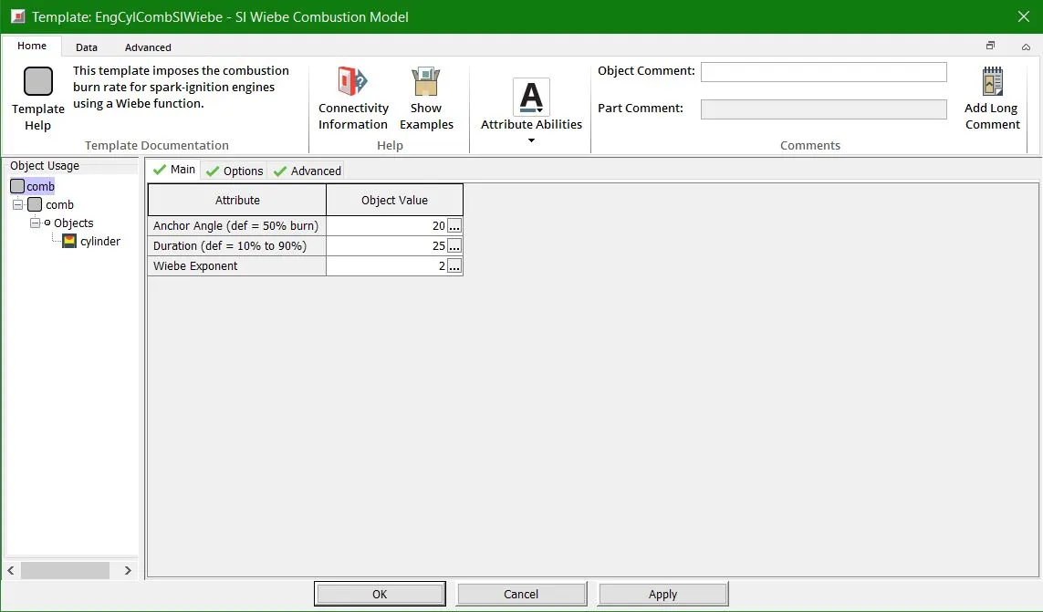
Now in order to change the MFB 50 we are changing the anchor angle to 20 deg
Angle "anchoring" the Wiebe curve to TDC or the name of a dependency reference object specifying the angle. The specified angle is the number of crank angle degrees between TDC and typically the 50% combustion point of the Wiebe curve. The attribute Burned Fuel % at Anchor Angle below may optionally be used to change the burn point in the Wiebe curve from 50%.
Results comparison
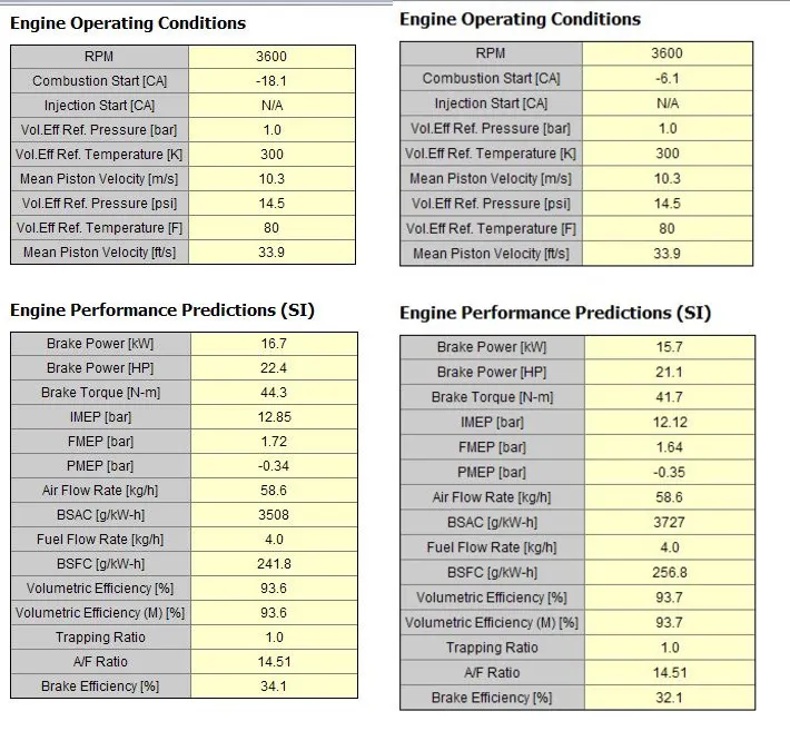
The anchor angle was changed from 8 deg to 20 deg . Now in the above image it is clear that there is a drop in the brake power produced and also reduces the brake torque and brake efficiency. There is however increase in BSFC but pressure inside the cylinder reduces.
CONCLUSION
- General comparison between SI and CI engine were observed
- MFB 50 is a critical engine parameter which reduces power and torque
- There was slight improvement in the BSFC of the engine
- The pressure inside the cylinder also reduces.