Cyclone Separator Challenge
AIM
The aim of this project is to simulate the Discrete Phase Model on the Cyclone separator
OBJECTIVES
- Cyclone separator efficiency study
- Simulate the cyclone separator by varying the particle diameter
- Simulate the cyclone separator by varying the particle velocity
CYCLONE SEPERATOR
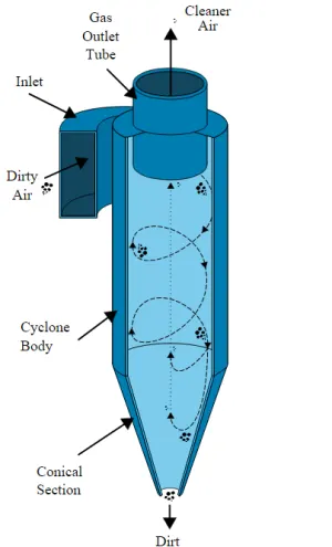
Cyclone separators or simply cyclones are separation devices that use the principle of inertia to remove particulate matter from flue gases. Cyclone separators is one of many air pollution control devices known as precleaners since they generally remove larger pieces of particulate matter. This prevents finer filtration methods from having to deal with large, more abrasive particles later on. In addition, several cyclone separators can operate in parallel, and this system is known as a multicyclone.It is important to note that cyclones can vary drastically in their size. The size of the cyclone depends largely on how much flue gas must be filtered, thus larger operations tend to need larger cyclones.
CYCLONE SPERATOR EFFICIENCY MODELS
Iozia and Leth Model
The model assumes that a particle carried by the vortex endures the influence of two forces: a centrifugal force, Z and a flow resistance, W . The collection efficiency η of particle diameter `d_p`can be calculated from
`eta=frac[1][1+[d_(pc)+d_(p)]^beta`
where, `beta`is the slope parameter which is given by
`beta=0.62-0.87ln(frac[d_(pc)][100])+5.21ln(frac[ab][D^2))+1.05ln(frac[ab][D))^2`
`d_(pc)`is the 50% cut size given by
`d_(pc)=[frac[9muQ][pirhopz_cv_t^2]]^0.5`
The core length `z_c`and the core diameter `d_c`are given by
`z_c=(H − S) − frac[H − S][(D/B)-1) (d_c/B)-1`
`d_c=0.47D(frac[ab][D^2])^(−0.25)(frac[De][D])^1.4`
Li and Wang Model
- Geometry
- Mesh
- Setup
- Solution
- Result
Geometry
In the geometry stage, when we import the geometry into spaceclaim the fluid volume is to be extracted from the solid model.
Once the fluid volume is extracted we have to supress the solid volume for physics from supress for physics option from the graphics window.
Mesh
- Solver - pressure solver
- Solver state - Steady state
- gravity - Gravity = -9.81 m/s^2 in the Y-direction
- Turbulence Model - K_epsilon RNG swirl dominated
- Discrete phase - Inlet velocity of anthracite particles = 3 m/s
- Particle size - Particle diameter = 1e-6 m
- Boundary Condition
- Inlet velocity of air = 3m/s
- Inlet - Reflect BC
- Outlet 1 - escape BC
- Outlet 2 - trapped BC
The solution has run for 1000 iterations and the solution has converged after 700 iterations.
CYCLONE SEPERATOR EFFICIENCY
The formula is given by
Efficiency = number of particles tracked / number of particles tracked
`eta =54/120xx100`
`eta=45%`
Results
Velocity Contour of particles
Pressure
Animation
- Geometry
- Mesh
- Setup
- Solution
- Result
Geometry
In the geometry stage, when we import the geometry into spaceclaim the fluid volume is to be extracted from the solid model.
Once the fluid volume is extracted we have to supress the solid volume for physics from supress for physics option from the graphics window.
Mesh
- Solver - pressure solver
- Solver state - Steady state
- gravity - Gravity = -9.81 m/s^2 in the Y-direction
- Turbulence Model - K_epsilon RNG swirl dominated
- Discrete phase - Inlet velocity of anthracite particles = 3 m/s
- Particle size - Particle diameter = 3e-6 m
- Boundary Condition
- Inlet velocity of air = 3m/s
- Inlet - Reflect BC
- Outlet 1 - escape BC
- Outlet 2 - trapped BC
The solution has run for 1000 iterations and the solution has converged after 700 iterations.
CYCLONE SEPERATOR EFFICIENCY
The formula is given by
Efficiency = number of particles tracked / number of particles tracked
`eta =88/120xx100`
`eta=73.33%`
Results
Velocity Contour of particles
Pressure Contour
Animation
- Geometry
- Mesh
- Setup
- Solution
- Result
Geometry
In the geometry stage, when we import the geometry into spaceclaim the fluid volume is to be extracted from the solid model.
Once the fluid volume is extracted we have to supress the solid volume for physics from supress for physics option from the graphics window.
Mesh
- Solver - pressure solver
- Solver state - Steady state
- gravity - Gravity = -9.81 m/s^2 in the Y-direction
- Turbulence Model - K_epsilon RNG swirl dominated
- Discrete phase - Inlet velocity of anthracite particles = 3 m/s
- Particle size - Particle diameter = 5e-6 m
- Boundary Condition
- Inlet velocity of air = 3m/s
- Inlet - Reflect BC
- Outlet 1 - escape BC
- Outlet 2 - trapped BC
The solution has run for 1000 iterations and the solution has converged after 700 iterations.
CYCLONE SEPERATOR EFFICIENCY
The formula is given by
Efficiency = number of particles tracked / number of particles tracked
`eta =116/120xx100`
`eta=96.67%`
Results
Velocity Contour of particles
Pressure Contour
Animation
- Geometry
- Mesh
- Setup
- Solution
- Result
Geometry
In the geometry stage, when we import the geometry into spaceclaim the fluid volume is to be extracted from the solid model.
Once the fluid volume is extracted we have to supress the solid volume for physics from supress for physics option from the graphics window.
Mesh
- Solver - pressure solver
- Solver state - Steady state
- gravity - Gravity = -9.81 m/s^2 in the Y-direction
- Turbulence Model - K_epsilon RNG swirl dominated
- Discrete phase - Inlet velocity of anthracite particles = 1 m/s
- Particle size - Particle diameter = 5e-6 m
- Boundary Condition
- Inlet velocity of air = 1 m/s
- Inlet - Reflect BC
- Outlet 1 - escape BC
- Outlet 2 - trapped BC
The solution has run for 1000 iterations and the solution has converged after 700 iterations.
CYCLONE SEPERATOR EFFICIENCY
The formula is given by
Efficiency = number of particles tracked / number of particles tracked
`eta =31/120xx100`
`eta=25.83%`
Results
Velocity Contour of particles
Pressure Contour
Animation
- Geometry
- Mesh
- Setup
- Solution
- Result
Geometry
In the geometry stage, when we import the geometry into spaceclaim the fluid volume is to be extracted from the solid model.
Once the fluid volume is extracted we have to supress the solid volume for physics from supress for physics option from the graphics window.
Mesh
- Solver - pressure solver
- Solver state - Steady state
- gravity - Gravity = -9.81 m/s^2 in the Y-direction
- Turbulence Model - K_epsilon RNG swirl dominated
- Discrete phase - Inlet velocity of anthracite particles = 3 m/s
- Particle size - Particle diameter = 5e-6 m
- Boundary Condition
- Inlet velocity of air = 3m/s
- Inlet - Reflect BC
- Outlet 1 - escape BC
- Outlet 2 - trapped BC
The solution has run for 1000 iterations and the solution has converged after 700 iterations.
CYCLONE SEPERATOR EFFICIENCY
The formula is given by
Efficiency = number of particles tracked / number of particles tracked
`eta =117/120xx100`
`eta=97.5%`
Results
Velocity Contour of particles
Pressure Contour
Animation
- Geometry
- Mesh
- Setup
- Solution
- Result
Geometry
In the geometry stage, when we import the geometry into spaceclaim the fluid volume is to be extracted from the solid model.
Once the fluid volume is extracted we have to supress the solid volume for physics from supress for physics option from the graphics window.
Mesh
- Solver - pressure solver
- Solver state - Steady state
- gravity - Gravity = -9.81 m/s^2 in the Y-direction
- Turbulence Model - K_epsilon RNG swirl dominated
- Discrete phase - Inlet velocity of anthracite particles = 5 m/s
- Particle size - Particle diameter = 5e-6 m
- Boundary Condition
- Inlet velocity of air = 5 m/s
- Inlet - Reflect BC
- Outlet 1 - escape BC
- Outlet 2 - trapped BC
The solution has run for 1000 iterations and the solution has converged after 700 iterations.
CYCLONE SEPERATOR EFFICIENCY
The formula is given by
Efficiency = number of particles tracked / number of particles tracked
`eta =117/120xx100`
`eta=97.5%`
Results
Velocity Contour of particles
Pressure Contour
Animation
- As the particle size increases the efficiency of the cyclone separator increases.
- After a particular size of particle there is no huge effect of particle size on efficiency of cyclone separator
- The discrete phase model is captured in the simulations
- The velocity of the particles also plays an important role in cyclone separator efficiency
- The pressure drop can be visualised from the pressure contours plots.