Challenge on Combustion
AIM
The aim of this challenge is to simulate the combustion process in a combustor
OBJECTIVES
The objectives of this simulation are
- Emission modelling for various reaction mechanisms
- Variation of mass fractions of different species for combustion model
- Effect of adding water content at the fuel inlet
COMBUSTION
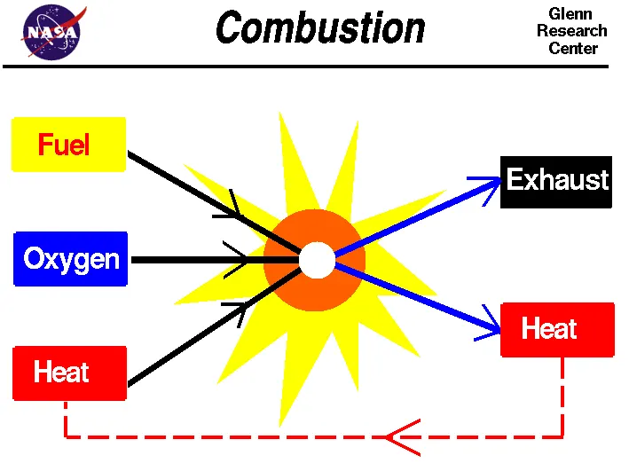
Combustion is a chemical process in which a substance reacts rapidly with oxygen and gives off heat. The original substance is called the fuel, and the source of oxygen is called the oxidizer. The fuel can be a solid, liquid, or gas, although for airplane propulsion the fuel is usually a liquid. The oxidizer, likewise, could be solid liquid or gas, but is usually a gas (air) for airplanes. For model rockets, a solid fuel and oxidizer is used.
During combustion, new chemical substances are created from the fuel and the oxidizer. These substances are called exhaust. Most of the exhaust comes from chemical combinations of the fuel and oxygen. When a hydrogen-carbon-based fuel (like gasoline) burns, the exhaust includes water (hydrogen + oxygen) and carbon dioxide (carbon + oxygen). But the exhaust can also include chemical combinations from the oxidizer alone. If the gasoline is burned in air, which contains 21% oxygen and 78% nitrogen, the exhaust can also include nitrous oxides (NOX, nitrogen + oxygen). The temperature of the exhaust is high because of the heat that is transferred to the exhaust during combustion. Because of the high temperatures, exhaust usually occurs as a gas, but there can be liquid or solid exhaust products as well. Soot, for example, is a form of solid exhaust that occurs in some combustion processes.
COMBUSTION SIMULATION
The combustion process invloves the following stages
- Geometry
- Mesh
- Setup
- Solution
- Results
Geometry
The first stage of the combustion process is the combustor 3D model from which the 2D model is extracted from the above model. First the planes were created and then split body command was used to cut the model into half and then pasted onto another design window.
Here we see that the radial direction is aligned along the x-axis and we are performing an axisymmetric flow and combustion simulation. There is a small inlet for the fuel and then air enters through the large intake above the fuel inlet.
Mesh
In the mesh module we create all triangular mesh elements by inserting method option. Here the size of the element is taken as 0.001m and the elements count goes upto 145540 elements.
Setup
For this simulation the setup was as follows
- solver - pressure solver
- solver state - steady state
- 2D space - Axisymmetric
- tturbulence model - k - epsilon model
- Chemistry model - Eddy Dissipation
- Mixture - methane air mixture
- Additional model - Species transport equations
- Boundary conditions
- Inlet velocity for air = 0.5 m/s
- mole fraction for oxygen = 0.23 moles
- Inlet velocity for air = 80 m/s
- Mole fraction for methane - 1
- Soot model - on with one step model
- Nox model - on with prompt and thermal checked
Residual plot
The simulation was run for 500 iterations and the solution has converged after 250 iterations.
Results
Temperature contour
Carbondioxide contour
Water contour
Methane contour
Nitrogen contour
Oxygen contour
Nitrous Oxide contour
Soot contour
Line probs
Line probes are created for the concentration variation of different species across the combustor
Temperature line plot
Carbondioxide line plot
Water line plot
Methane line plot
Nitrogen line chart
Oxygen line plot
Nitrogen oxide line plot
Soot line plot
EFFECT OF WATER VAPOUR ON EMISSIONS
In this part of the simulation the water vapour is added in the fuel from 5% to 30% by mole percentage and observe the contour and line plots
Temperature Contour
Carbondioxide contour
Water Contour
Methane contour
Nitrogen contour
Oxygen contour
Nitrogen oxide contour
Soot contour
Temperature line plot
Carbondioxide line plot
Water line plot
Methane line plot
Nitrogen line plot
Oxygen line plot
NOX line plot
Soot line plot
CONCLUSION
- There is a drop in the level of nitrogen oxides as water content in the fuel is increased
- Similarly, soot levels also decreases
- Temperature also increases as water content is added to the fuel
- Unburnt hydrocarbons forms at much faster rate as water is added
- Incomplete combustion could be a result of having water
- The various species of the combustion in the reaction mechanism is seen
- The species transport and the eddy dissipation is applied in this simulation
- Thus it is concluded that the combustion simulation helps to see the detailed chemical kinetics study