Project - 2 - Meshing on the suspension Assembly
Project 2 Challenge: Meshing of the Suspension Assembly using ANSA Preprocessor tool
Course: Preprocessor for Structural Analysis using ANSA
Submitted by: Amanpreet Singh Whan
Supervisor: David Nirmal Paul
February 04, 2021
Abstract
The suspension is the system of tires, tire air, springs, shock absorbers, and linkages that connects a vehicle to its wheels and allows relative motion between the two. The suspension also protects the vehicle itself and any cargo or luggage from damage and wear. The report presents a strategy that was adopted to mesh the given Rear Wheel Suspension CAD model using the ANSA Pre-Processor tool for the fulfillment of the Project 2 Challenge Task. The meshing is a three-step process that includes geometry clean-up, mid surface extraction and finally performing meshing using setting quality and mesh parameters. The max quads percentage and max trais percentage were found to be 1.27% and 98.73 % respectively. Moreover, the report also presents the deployment of connections such as RBE2, and seam weld connections across different regions of the discretized Rear Wheel Suspension Model.
List of Figures
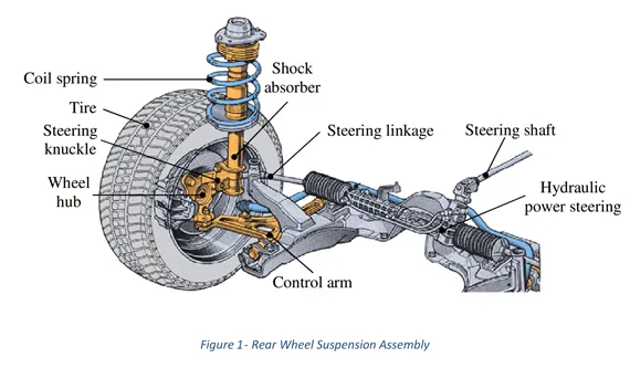
Figure 1- Rear Wheel Suspension Assembly.
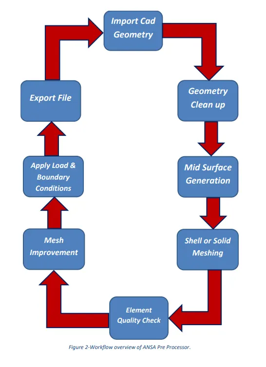
Figure 2-Workflow overview of ANSA Pre Processor.
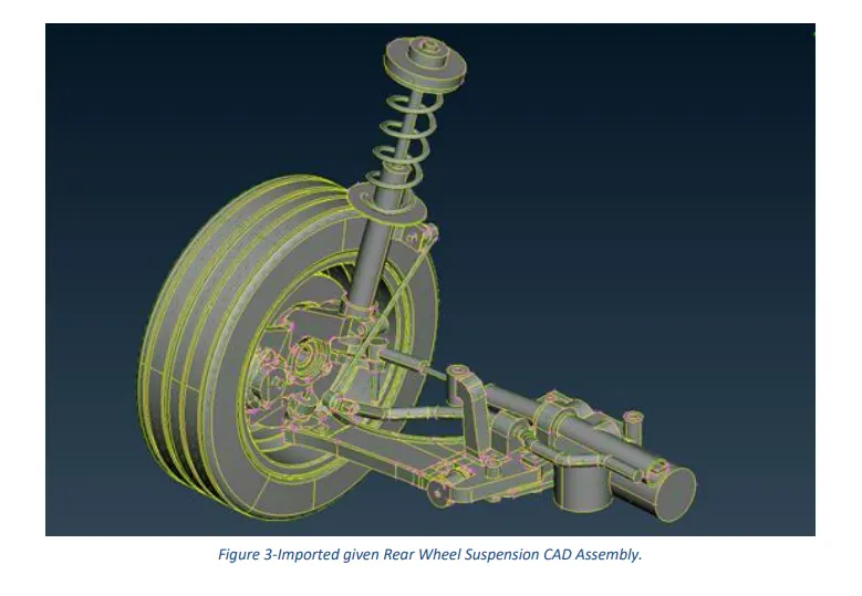
Figure 3-Imported given Rear Wheel Suspension CAD Assembly.
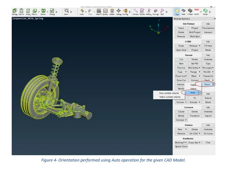
Figure 4- Orientation performed using Auto operation for the given CAD model.
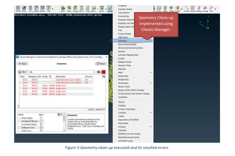
Figure 5-Geometry clean-up executed and its resulted errors.
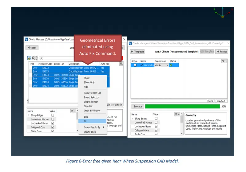
Figure 6-Error free given Rear Wheel Suspension CAD Model.
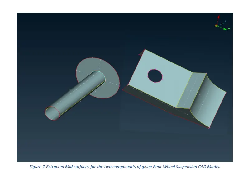
Figure 7-Extracted Mid surfaces for the two components of the given Rear Wheel Suspension CAD Model.
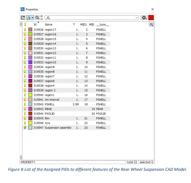
Figure 8-List of the Assigned PIDs to different features of the Rear Wheel Suspension CAD Model.
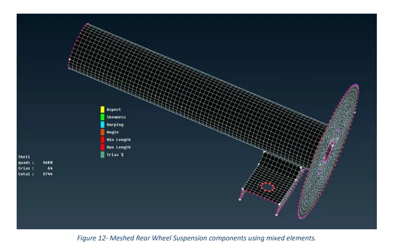
Figure 12- Meshed Rear Wheel Suspension components using mixed elements.
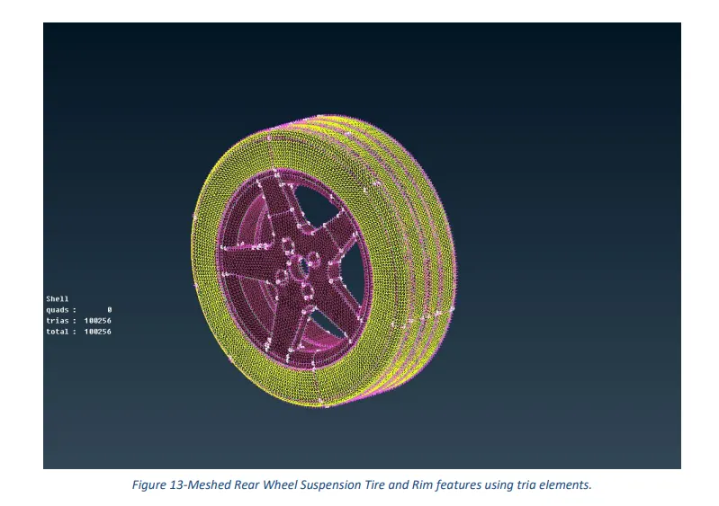
Figure 13-Meshed Rear Wheel Suspension Tire and Rim feature using tria elements.
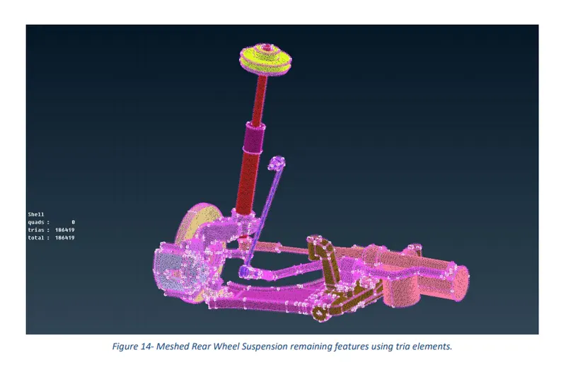
Figure 14- Meshed Rear Wheel Suspension remaining features using tria elements.
Figure 15-Shocker component of Rear Wheel Suspension CAD model meshed using CBAR elements.
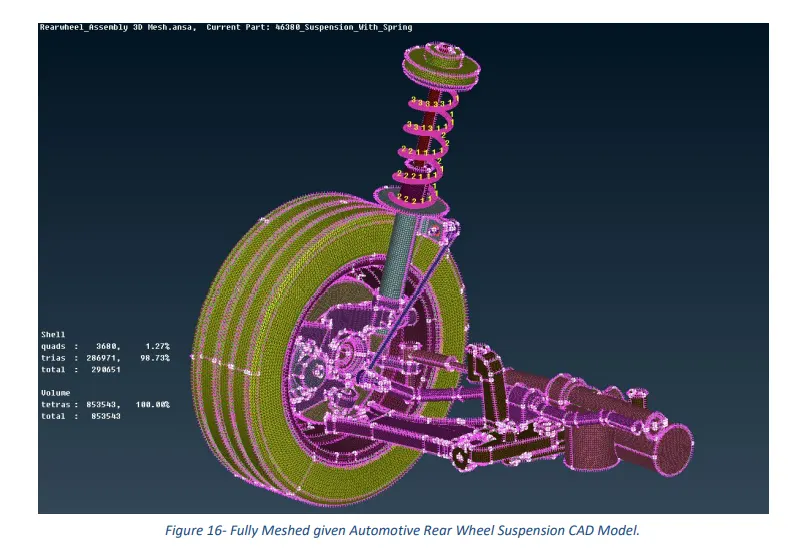
Figure 16- Fully Meshed given Automotive Rear Wheel Suspension CAD Model.
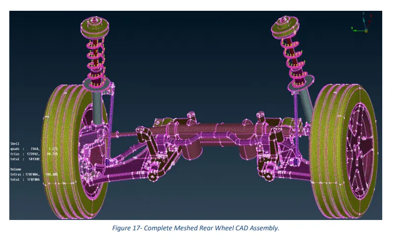
Figure 17- Complete Meshed Rear Wheel CAD Assembly.
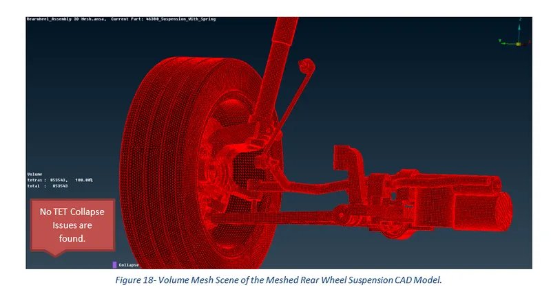
Figure 18- Volume Mesh Scene of the Meshed Rear Wheel Suspension CAD Model.
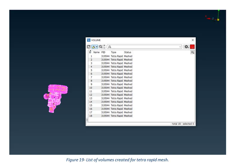
Figure 19- List of volumes created for tetra rapid mesh.
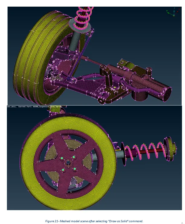
Figure 21- Meshed model scene after selecting the "Draw as Solid" command.
Table of Contents
3.1 Import CAD Model and do Geometry Clean-Up.
1 Introduction
The suspension system of a vehicle refers to the group of mechanical components that connect the wheels to the frame or body. In the horse and buggy days, the suspension system consisted merely of a beam (axle) that extended across the width of the vehicle. In the front, the wheels were mounted to the axle ends and the axle was rotated at the center to provide steering. The early automobiles used the one‐piece axle design but instead of being rotated at the center, it was fix‐mounted to the vehicle through springs to provide the cushioning of shock loads from road inaccuracies. The wheels were rotationally mounted at the axle ends to provide steering. The first springs consisted of thin layers of narrow pieces of strip steel stacked together in an elliptical shape and were called leaf springs. In later installations, leaf springs were replaced by coil springs. In front‐engine rear‐drive vehicles, the front beam axle was replaced by independently mounted steerable wheels. The wheels were supported by short upper and lower hinged arms holding them perpendicular to the road as did the previous axle beam designs. A coil spring was used to support either the upper or the lower arm to provide dampening. Shock absorbers began to be used to dampen shock loads and to provide resistance to spring oscillations. The power transmitting drive axle in the rear served as the beam‐type suspension with dampening provided by either leaf or coil springs as well as shock absorbers.
When front‐engine front‐drive passenger cars were introduced, the upper arm was rotated up and replaced by a member called a “strut” which contained the concentrically mounted spring and shock. This arrangement provided additional space for transverse-mounted engine/transmission modules and the front driveshaft. This same type of suspension was also used in the rear of many cars. Trucks continue to be front‐engine, rear‐drive vehicles many of which are using beam-type axle suspension systems in both the front and rear.
2 Aims
- Check and fix all the geometry errors of the given Cad Model for Geometry Clean-up purposes.
- Extract/ Generate Middle Surface for the components of the given CAD model.
- Perform both Shell and Solid Meshing of the model as per given Mesh Quality Criterion to generate an overall good mesh flow for the entire model.
- Investigate and Improve the mesh quality wherever required.
- Choose and Deploy the most appropriate connectors or connections from the Nastran deck to connect different features of the Meshed Model.
3 Methodology and Results
The section describes the different stages that were performed using an engineering tool, ANSA Pre-Processor for the successful generation of an overall good mesh for the completion of the Project 2 Challenge. These stages can be further broadly sub-categorized into three key steps, starting from importing of cad model to geometry clean-up for mid surface generation and finally carry out shell and solid meshing as per quality requirements.
ANSA Pre Processor is an advanced computer-aided engineering tool extensively used for FEA (Finite Element Analysis) and CFD (Computational Fluid Dynamics) analysis in the automotive and aerospace industry. ANSA pre-processor is a CAE software developed by BETA CAE Systems and follows a strict workflow when numerically solving a given problem. Figure 1 represents the workflow overview implemented in the software.
3.1 Import CAD Model and do Geometry Clean-Up
After opening the ANSA Pre-processor software, the first and the foremost step is to import the CAD geometry and perform topology using the topo command in the faces section of Topo Module Buttons for the entire model.
In the next step, go to the Checks Manager and select geometry from the options list. The main function of the Checks geometry is to locate geometrical issues such as unmeshed macros, unchecked faces, needle faces, collapsed cons, triple cons, and cracks. Even though most of these errors can be easily eliminated using the Auto-Fix command but issues concerning triple cons must be fixed manually by releasing Cons or Hot-points (nodes) and joining cons/ nodes back again using the topo command. Before executing the Checks geometry operation, make sure to turn on the most essential above stated geometry issues.
What follows hereafter is the set of images showing different results obtained before and after the completion of geometry clean-up using ANSA Pre-Processor software.
3.2 Mid Surface Extraction
The mid surface can be generated both manually and automatically. A manual mid surface can be obtained using the Faces->Offset command in the Faces section of Topo module buttons. Moreover, the mid-surface generated using manual operation must be assigned a new PID which can be easily done using the Set PID command in the faces section. However, ANSA directly assigns a new PID to a Mid Surface that is extracted automatically, and it is usually accomplished using the Mid Surface->Skin command in the faces section.
The results of the mid surfaces obtained manually (using the commands, Faces->offset and Curves-> Middle) for the different regions of the given CAD model are presented in the following pictures.
3.3 Meshing
Meshing is a phase where the CAD geometry is discretized to represent the computational domain in which the solver will discover a solution. A refined mesh helps to achieve better results.
The meshing conducted for the given model is explained in the following steps:
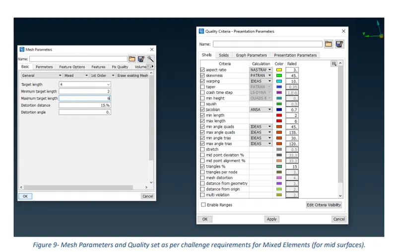
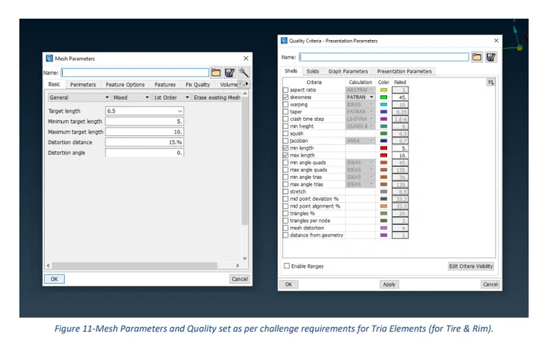
- After the extraction of mid surface, the Perimeters length was set to 4mm in the perimeters section of the Mesh module buttons. However, the length of the perimeter was set to 6.5mm for the Tire and Rim features of the model. This will help to generate a mesh of constant element size.
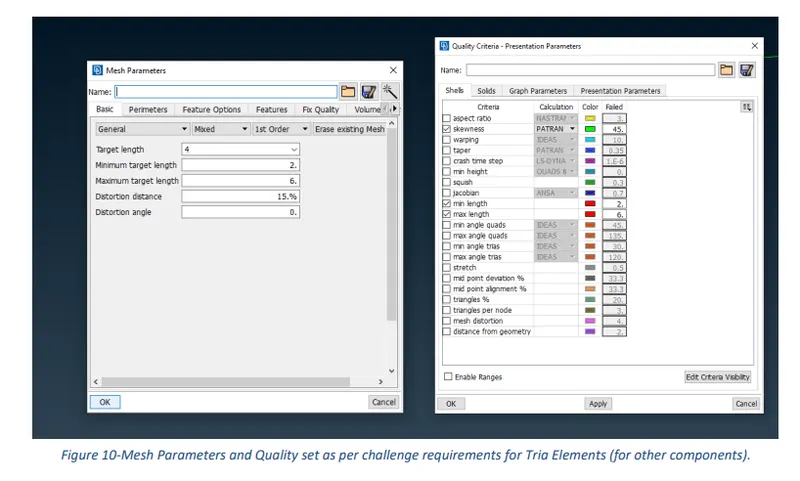
- In the next step, the values of Quality Criteria and Mesh Parameters were entered as per challenge requirements to get a good flow of the mesh over the model. The values used for the quality criteria and mesh parameters are presented in the following tables.
Table 1-Quality criteria and their respective assigned values.
|
Quality Criteria for mixed elements (mid surface components) |
|
|
Criteria |
Value |
|
Aspect Ratio |
3 |
|
Skewness |
45 |
|
Warping |
15 |
|
Jacobian |
0.7 |
|
Min length |
2 |
|
Max length |
6 |
|
Min angle quads |
45 |
|
Max angle quads |
135 |
|
Min angle trias |
30 |
|
Max angle trias |
120 |
|
Tria Percentage |
15 |
Table 2- Quality criteria used for Solid Meshing of Tire and Rim.
|
Quality Criteria for Tria elements (Tire and rim) |
|
|
Criteria |
Value |
|
Skewness |
45 |
|
Min length |
5 |
|
Max length |
10 |
|
Tet Collapse |
0.2 |
Table 3- Quality criteria used for Solid Meshing of the other components.
|
Quality Criteria for Tria elements (other features) |
|
|
Criteria |
Value |
|
Skewness |
45 |
|
Min length |
2 |
|
Max length |
6 |
|
Tet Collapse |
0.2 |
Table 4- Mesh Parameters used for mid surface components.
|
Mesh Parameters for Mixed elements (Mid surface components) |
|
|
Parameters |
Value |
|
Target length |
4 |
|
Minimum target length |
2 |
|
Maximum target length |
6 |
|
Distortion distance |
15% |
|
Distortion angle |
0 |
Table 5- Mesh Parameters used for Tire and Rim.
|
Mesh Parameters for Tria elements (Tire and Rim) |
|
|
Parameters |
Value |
|
Target length |
6.5 |
|
Minimum target length |
5 |
|
Maximum target length |
10 |
|
Distortion distance |
15% |
|
Distortion angle |
0 |
Table 6-Mesh parameters used for other features.
|
Mesh Parameters for Tria elements (other features) |
|
|
Parameters |
Value |
|
Target length |
4 |
|
Minimum target length |
2 |
|
Maximum target length |
6 |
|
Distortion distance |
15% |
|
Distortion angle |
0 |
- A combination of the ‘Best’ and ‘Spot Mesh’ Mesh Generation algorithms was used to produce mesh for the model.
- Quality failing elements were eliminated using multiple approaches which include Reconstruction of mesh, smoothing of mesh, Moving & Pasting Grids and Splitting, Swapping & Joining of elements.
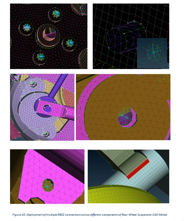
The results of the meshed model are presented in the following pictures.

4 Discussion
ANSA Pre-Processor was used to mesh the Rear Wheel Suspension CAD model as per asked Quality Criteria and Mesh Parameters to generate a good overall mesh flow for the successful completion of the Project 2 Challenge. To fulfill the requirements of the challenge, Geometry clean-up along with Mid Surface extraction and Meshing was performed and the obtained results are presented in the figures shown above.
In figure 5, it can be clearly seen that the provided CAD model had multiple errors such as needle faces, cracks, unchecked faces, and triple cons which were fixed using both manual and automated approaches.
In PID mode, by selecting the extracted mid surface and the parent component while keeping the parent component in transparency mode and it was found that the mid extracted falls exactly in the middle of the parent component of geometry, concluding mid extraction performed was accurate and precise.
The construction lines were suppressed or manipulated by a certain amount in some critical areas of the geometry where quality could possibly fall to generate an overall good flow of the mesh for the entire model.
Figures 20 represent different RBE2 connections created in multiple areas of the meshed rear wheel suspension CAD model. RBE2 defines a rigid body element of form 2 between selected grid points, 3d points, etc. The CM was assigned a value of 123456 which means the connection deployed is rigid and restricts motion in all 6 degrees of freedom.
5 Conclusion
In conclusion, the main aim of the challenge was to do a geometry clean-up of the Rear Wheel Suspension CAD model, generate its mid surface, perform both shell & solid meshing, and deploy the most suitable connections to attach different components to each other. The max quads percentage was found to be 1.27 % while the max trias percentage was found to be 98.73 %. Lastly, the meshed model was assigned a thickness by enabling the ‘Draw shell as solid’ command in the Quality Criteria- Presentation Parameters tab.
6 Learning Outcomes
Throughout this challenge, I have gained knowledge about different commands that are used to fix geometry errors and are used to generate the mid surface of any CAD Model with both auto and manual options. I have also learned that the Mesh Quality can be fixed using several operations like ‘mesh reconstruction’, ‘mesh smoothing,’ ‘grids move or paste’, and ‘elements split and join’. Lastly, the procedures that are used to deploy different connections across the different parts of CAD design.
Appendix
Link to access the completed Challenge:
https://drive.google.com/file/d/1Clp2dwIj1NWsTbUmsBZ6jBO4A3i9LZbt/view?usp=sharing