Assignment 3-2D Element Formulation Challenge
Assignment 3: 2D Element Formulation Challenge
Course: Crashworthiness Analysis using HyperMesh and Radioss
Submitted by: Amanpreet Singh Whan
Supervisor: Harsha Chowdary
December 18, 2021
List of Figures
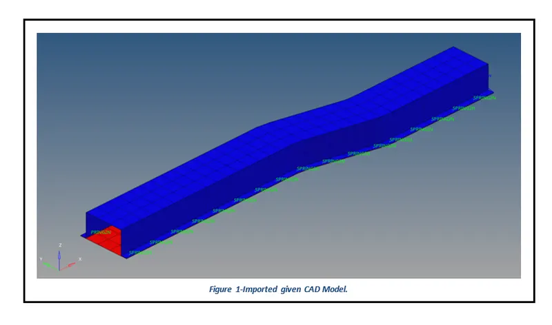
Figure 1-Imported given CAD Model.
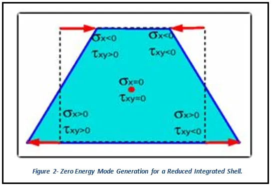
Figure 2- Zero Energy Mode Generation for a Reduced Integrated Shell.
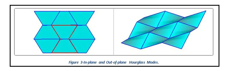
Figure 3-In-plane and Out-of-plane Hourglass Modes.
Figure 9- Rigid Wall Force results for the crash analysis using the default elemental properties.
Figure 12- Global Energy plots for the crash analysis using the default elemental properties.
Figure 14-Global Energy plots for the crash analysis using the recommended elemental properties.
Table of Contents
3.2 Creating Input Deck for Crash Simulation.
1 Introduction
HyperMesh is the market-leading, multi-disciplinary finite element pre-processor which manages the generation of the largest, most complex models, starting with the import of CAD geometry to exporting a ready-to-run solver file. HyperMesh supports a wide variety of CAD and solver interfaces, making it a perfect solution for most industry verticals and domains. With its advanced geometry and meshing capabilities, HyperMesh provides an environment for rapid model generation. Generating high-quality mesh quickly is just one of Hyper Mesh’s core competencies. For complex sub-system generation and assembly, HyperMesh has advanced model assembly tools. Modeling of laminate composites is supported by advanced creation, editing, and visualization tools. Design changes can be made easily via mesh morphing and geometry dimensioning.
2 Aims
- Run the crash simulations using both default and given elemental properties.
- Perform mass and energy checks and determine whether the results are acceptable or not.
- Plot Rigid Wall Forces, Internal Energy, Hourglass Energy, Contact Energy, Total Energy results for both simulations and compare the results for the same.
3 Methodology and Results
The section describes the different stages that were performed using an engineering tool HyperWorks Radioss 2020 for the completion of the Assignment 3 Challenge. These stages can be further broadly sub-categorized into three key steps, starting from importing of cad model to creating simulation cards and finally performing the crash simulation to obtain desired results.
3.1 Importing of CAD Model
After opening the HyperWorks software, the first step is to select the Radioss profile and then open the given CAD model.
3.2 Creating Input Deck for Crash Simulation
Element Configurations: Each element has an associated element configuration. An element configuration tells HyperWorks how to draw, store, and work with the element.
- 1D Elements include Spring, Trusses, and Beam elements.
- 2D Elements include Quads and Trias.
- 3D Elements include Solid Elements such as Hexa and Tetra elements.
Hourglass Formulations: Hourglass (HG) modes are nonphysical, zero-energy modes of deformation that produce zero strain and no stress. Hourglass modes occur only in under-integrated (single integration point) solid, shell, and thick shell elements.
As shown in Figure 2 for an anti-symmetric deformation of a shell element with one integration point at the center, a zero-energy mode can be found for a physical deformation mode. That cannot be true from a physical point of view and must be corrected. For a shell mesh, the two main hourglass modes are in-plane (membrane mode) and out-of-plane (W mode).
The two correcting methods available are:
- Perturbation or penalty method: Hourglass control by application of anti-hourglass forces to maintain deformation stability of the element.
- Physical stabilization method: Hourglass control by the correction of internal energy in an analytical way.
For the first method, four formulations are available in Radioss:
- Type 1 (Default option): Only in-plane modes are corrected, valid for shells and solids.
- Type 2: Old formulation no longer recommended.
- Type 3: Plasticity is considered in the computation of anti-hourglass forces; in-plane and out-of-plane hourglass modes are corrected; available only for shells.
- Type 4: Like Type 1 with additional higher-order terms in the computation of anti-hourglass forces and with out-of-plane hourglass mode correction; available only for shells.
The second method is powerful and can be used when the mesh quality is good. The physical stabilization method is incorporated in the following Radioss elements:
- QEPH shell
- HEPH solid
- HSEPH solid shell
The choice of hourglass formulation plays an essential role in the quality of results. If the mesh is fine enough, the physical stabilization method can be used. Otherwise, Type 3 and Type 4 formulations are recommended for shell meshes. When the material undergoes elastic-plastic behavior, the Type 3 formulation is much more efficient. The hourglass coefficient, hm and hf are recommended to be set to 0.1; however, the default value, hf=0.01 can be used for hr.
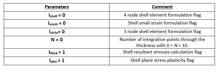
Default Elemental Properties:
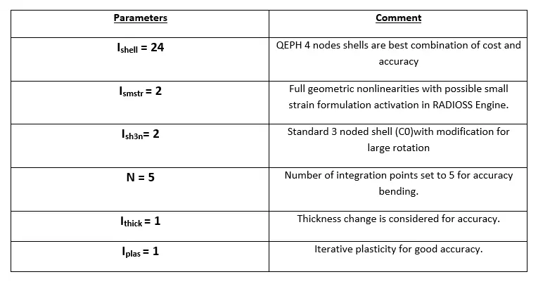
Recommended Element Formulation for Crash Analysis:
Assigning values to Timestep and Animation Steps Parameters:
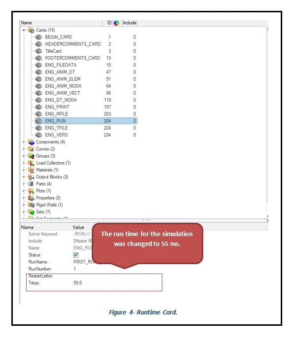
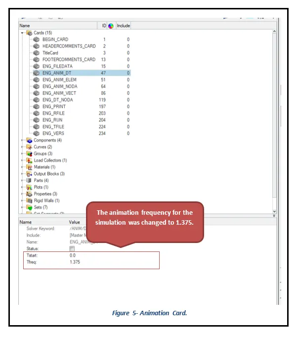
The assigning of values to Timestep and the Number of animation steps parameters was carried out using the following processes. The run time for the simulation was chosen to be 55 ms and the tfreq (=1.375) or a number of animation steps were chosen to be 40.
Model-> Cards-> Eng Run-> Select T stop and enter 55 ms.
Model-> Cards-> Eng Anim DT-> Select T Freq and enter 1.375.
Energy error and Mass Error Checks:
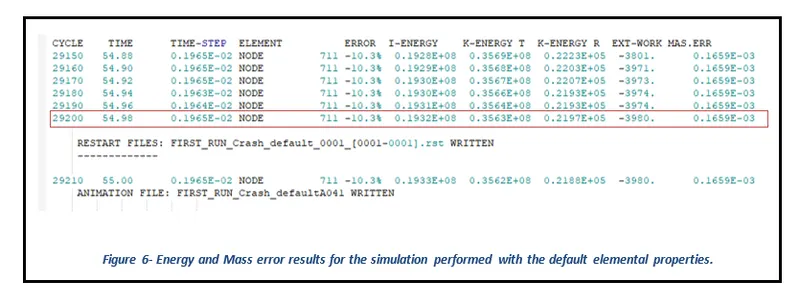
The Energy error should be negative and decrease with the iterations. Thus, ideally, the error should be at most -15% and better to have -5%. The closer to 0% error the better. The Mass error of less than 2% is preferred for the crash simulations.
Case 1: Energy and mass errors Results for the crash analysis using default elemental properties.
Case 2: Energy and mass errors Results for the crash analysis using suggested elemental properties.
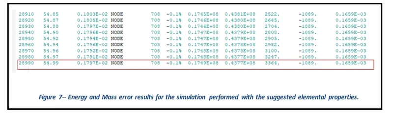
As it has already been discussed above that the Energy Error must be within the range of -15% to 5% while the Mass Error has to be below 2%. From Figures 6 and 7, it can be concluded that the results of mass and energy errors for both the crash tests fall within the nominal range. The negative energy error here indicates the dissipation of energy.
Rigid Wall Forces Results:
The rigid wall forces are generally the forces experienced by the wall during a crash test. For the challenge purposes, the Total Resultant Force graphs were plotted for both the crash test analysis.
Case 1: Rigid Wall Forces Results for the crash analysis using default elemental properties.
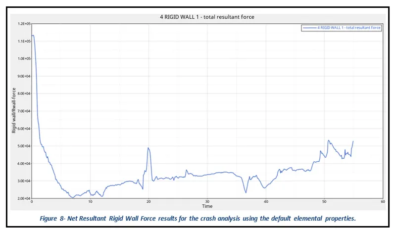
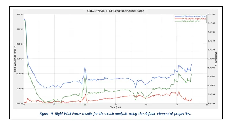
From Figure 8, it can be observed that at the time of impact (at t=0) the rigid wall experiences the most force which is equal to 113356.72 N, and then the resultant force goes on decreasing and become constant until the system comes to rest. In addition, at 20 ms there is a spike in resultant force which could essentially be due to an increase in the frictional forces of the system. Similarly, at 35 ms there is a slight decrease in resultant force which could be the result of the frictional force in the system. Figure 9 clearly indicates that with an increase in frictional forces there is an increase in net resultant rigid wall force and vice versa. However, the total resultant force is less than the resultant normal force which is the resultant of the high energy error caused by the usage of default elemental parameters.
Case 2: Rigid Wall Forces Results for the crash analysis using recommended elemental properties
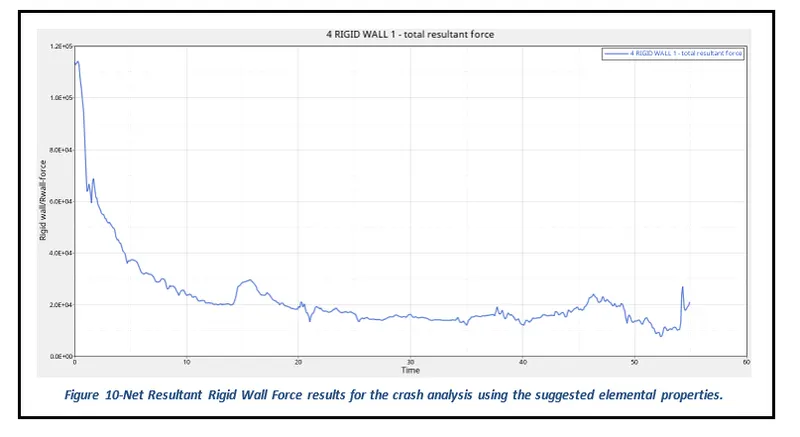
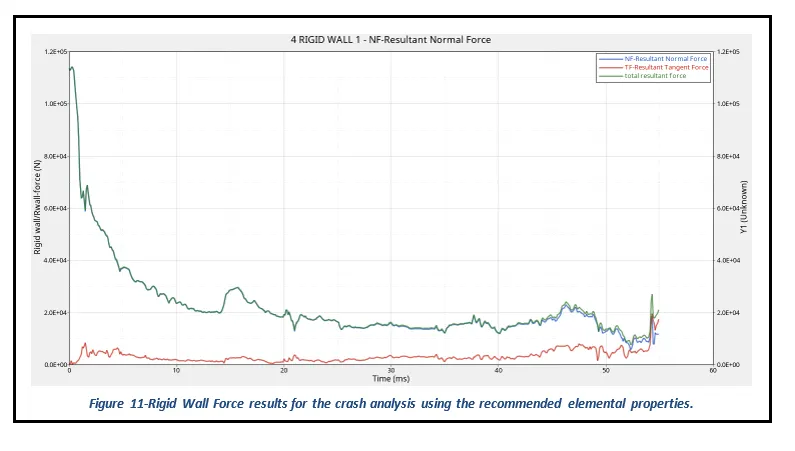
From Figure 10, it can be observed that at the time of impact (at t=0) the rigid wall experiences the most force which is equal to 113356.72 N, and then the resultant force goes on decreasing and become constant until the system comes to rest. In addition, at 55 ms there is a spike in resultant force which could essentially be due to an increase in the frictional forces of the system. Figure 11 clearly indicates that with an increase in frictional forces there is an increase in net resultant rigid wall force and vice versa. However, the total resultant force curve behaves almost in a similar fashion in comparison to the resultant normal force curve because of having low energy error resulting from the simulation using the recommended elemental properties.
Internal Energy, Hourglass Energy, Contact Energy, and Total Energy Results:
The Total Energy reported by Global variables in Radioss is the sum of:
- internal energy
- kinetic energy
- contact (sliding) energy
- hourglass energy
- system damping energy
- rigid wall energy
Case 1: Global Energy Results for the crash analysis using default elemental properties
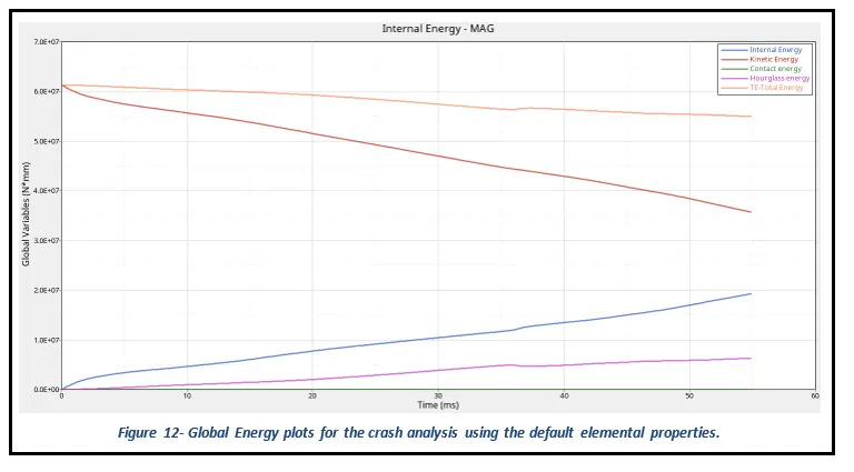
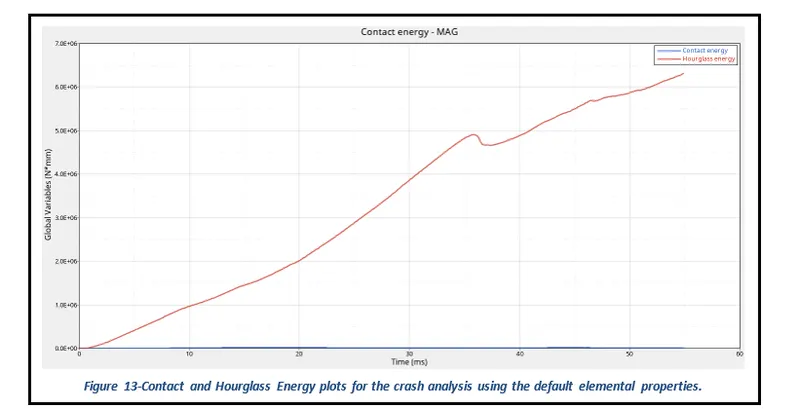
From figure 12, it can be seen that at the time of impact (t=0 ms) kinetic energy is maximum and internal energy is minimum but with an increase in time there is a reduction in kinetic energy while there is an increase in internal energy of the system and after that both energies become constant. This validates the principle of conservation of energy which states that energy can neither be created nor destroyed but can be converted from one form of energy to another. From figure 13, it can be observed that the hourglass energy generated at the end of the runtime is quite high which has essentially occurred due to a reduction in the stiffness of the elements caused by default elemental properties.
Case 2: Rigid Wall Forces Results for the crash analysis using recommended elemental properties
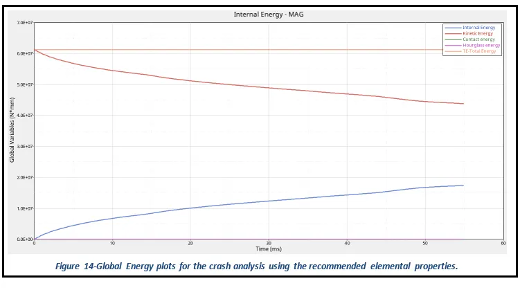
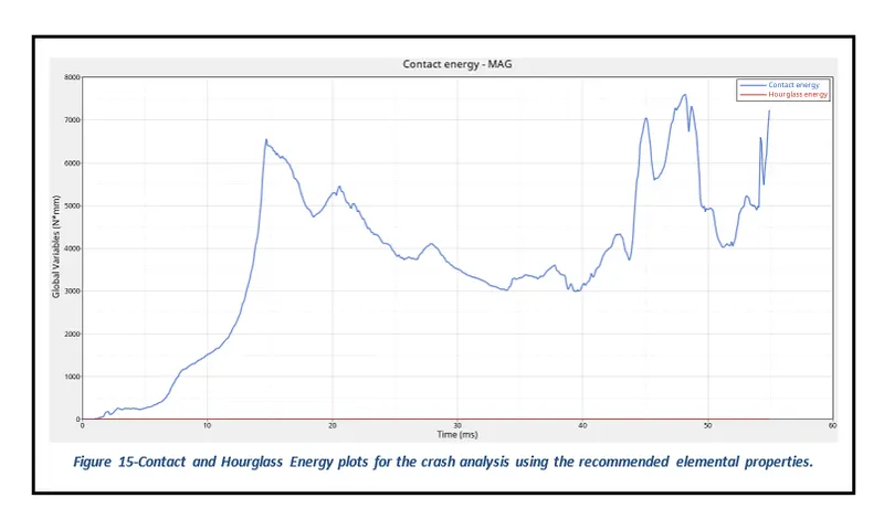
From figure 14, it can be seen that at the time of impact (t=0 ms) kinetic energy is maximum and internal energy is minimum but with an increase in time there is a reduction in kinetic energy while there is an increase in internal energy of the system and after that both energies become constant. This validates the principle of conservation of energy which states that energy can neither be created nor destroyed but can be converted from one form of energy to another. From figure 15, it can be observed that the hourglass energy generated at the end of the runtime is quite small and almost negligible in comparison to the results obtained from the simulation using default elemental properties.
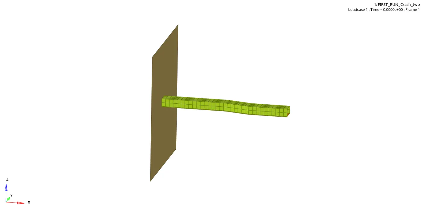
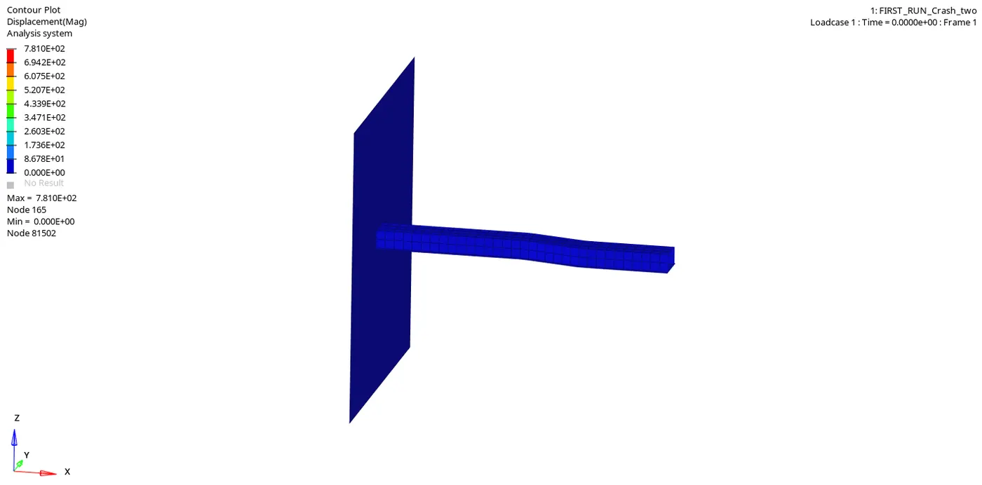
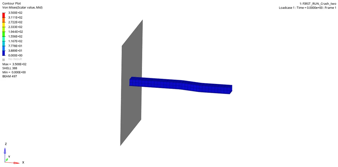
Displacement and Von Moises Stress Results:
Case 1: Displacement and Von Moises Stress Results for the crash analysis using default elemental properties
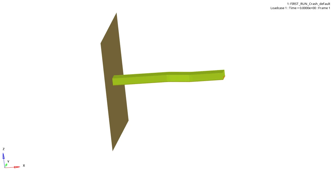
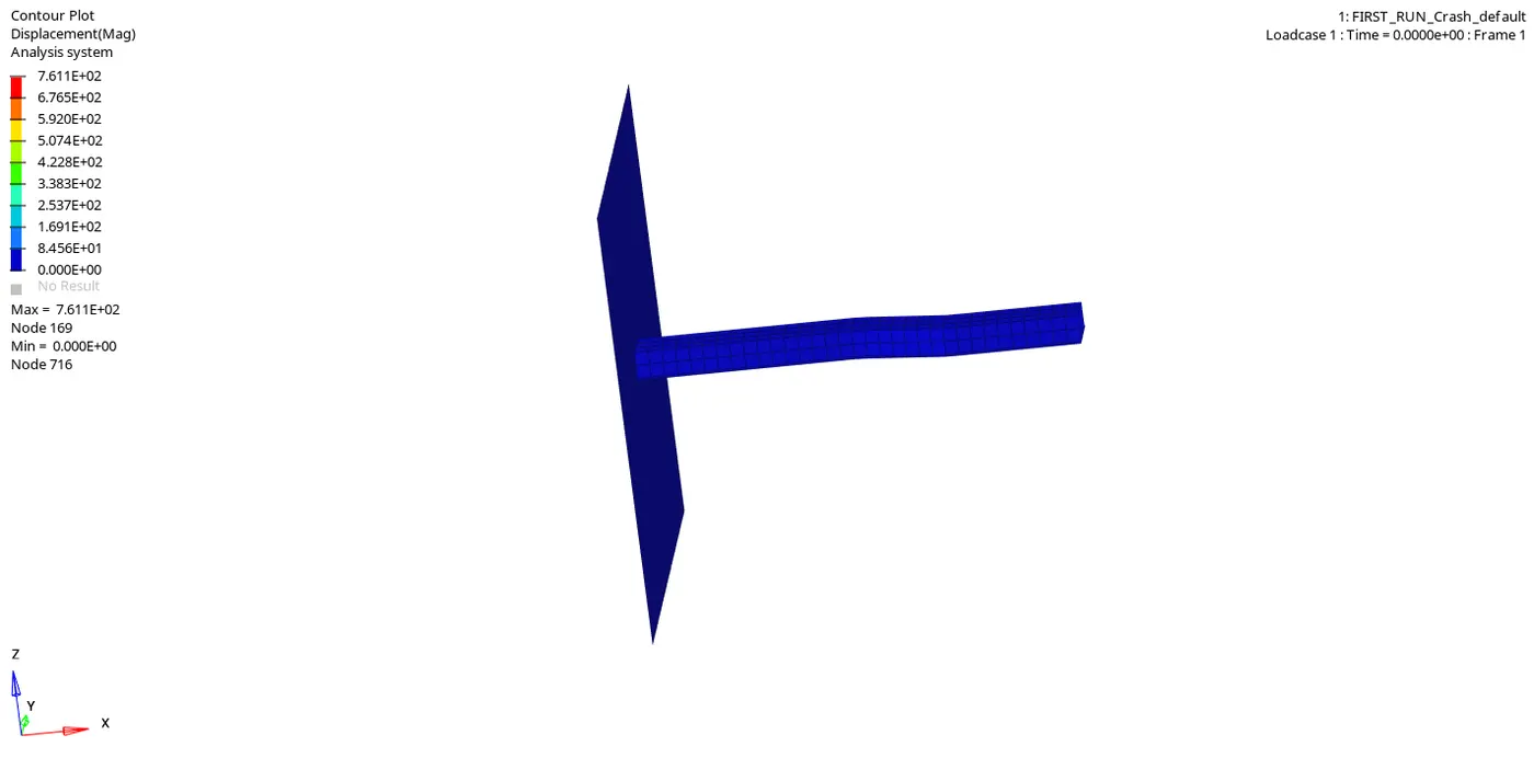
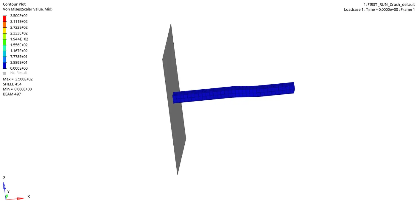
Case 2: Displacement and Von Moises Stress Results for the crash analysis using recommended elemental properties
|
Parameters |
Case 1 (Default properties) |
Case 2 (Suggested properties) |
|
Energy Error |
-10.3 % |
-0.1 % |
|
Internal Energy |
1.75 E+07 |
1.93 E+07 |
|
Kinetic Energy |
3.57 E+07 |
4.38 E+07 |
|
Hourglass Energy |
Hourglass energy increases with time since no physical stabilization established in default properties |
Hourglass energy is negligible since physical stabilization was established. |
|
Total Energy |
With the increase in hourglass energy, there is a reduction in total energy |
The total energy almost remains constant |
|
Results |
Results are less accurate |
Results are more precise and accurate |
4 Conclusion
In conclusion, the main aim of assignment 3 was to perform crash simulations of the given model using both defaults and recommended elemental properties. Perform mass and energy error checks and determine whether the results are acceptable. Lastly, plot rigid wall forces and global energy plots and compare the obtained results for the same.
After performing the simulations for both cases, it was found that the error in energy yielded by the simulation run with default elemental parameters was -10.3 % while the simulation run with recommended elemental properties was found to be -0.1 %. The high energy error caused by the default elemental properties had a drastic impact on the results plotted for the rigid wall forces. Moreover, since default elemental properties have no physical stabilization or have low values for element stiffness, a high increase in hourglass energy at the end of simulation was observed, affecting the total energy of the system and thus other important results.
Considering the above-discussed aspects of both the simulations, it would not be wrong to say that the crash simulation performed using the recommended elemental properties not only reduced the mass and energy error significantly but also yielded more accurate and precise results.