Week 9-Creation of 1D Connectors Challenge
Week 9 Challenge: Creation of 1 D Connectors Challenge
Course: HyperMesh for FEA Plastics and Sheet Metal Applications
April 10, 2021
Submitted by: Amanpreet Singh Whan
Supervisor: David Nirmal Paul
List of Figures
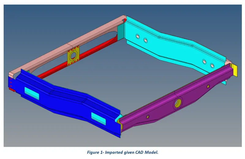
Figure 1- Imported given CAD Model.
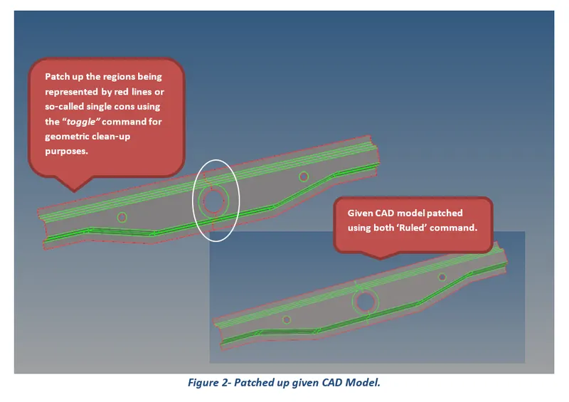
Figure 2- Patched up given CAD Model.
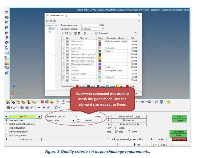
Figure 3-Quality criteria set as per challenge requirements.
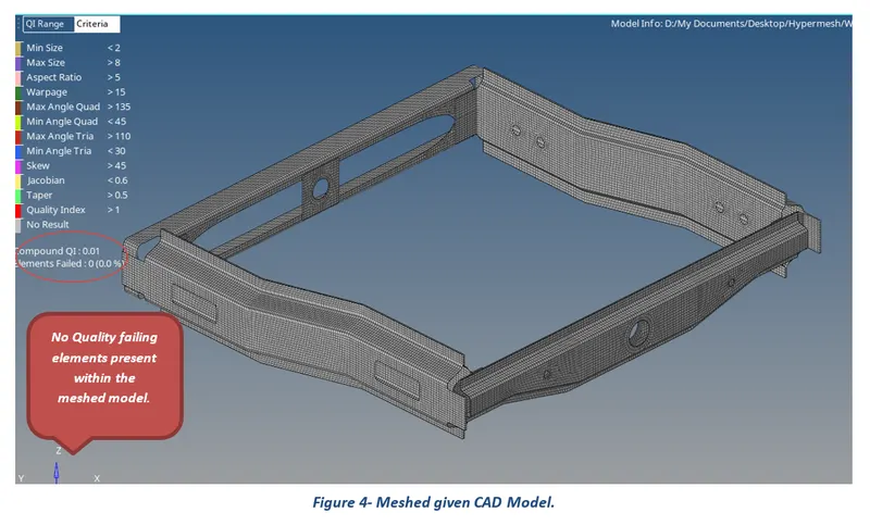
Figure 4- Meshed given CAD Model.
Figure 5- Process to be followed to deploy a connection.
Figure 6- Deployed Seam Quad connection between Right Rail 2and Front Truss 1 components.
Figure 7- Deployed connections across different components of the given CAD Meshed Model.
Table of Contents
3.1 Importing and Performing Geometry Clean-up of the CAD Model
3.2 2D or Shell Meshing of the given CAD Model
1 Introduction
HyperMesh is the market-leading, multi-disciplinary finite element pre-processor which manages the generation of the largest, most complex models, starting with the import of CAD geometry to exporting a ready-to-run solver file. HyperMesh supports a wide variety of CAD and solver interfaces, making it a perfect solution for most industry verticals and domains. With its advanced geometry and meshing capabilities, HyperMesh provides an environment for rapid model generation. Generating high-quality mesh quickly is just one of Hyper Mesh’s core competencies. For complex sub-system generation and assembly, HyperMesh has advanced model assembly tools. Modeling of laminate composites is supported by advanced creation, editing, and visualization tools. Design changes can be made easily via mesh morphing and geometry dimensioning.
2 Aims
- Check and fix all the geometry errors of the given Model for Geometry Clean-up purposes.
- Set the element size and the type of mesh required.
- Perform 2D or Shell Meshing of the model as per the given Mesh Quality Criterion to generate an overall good mesh flow for the entire model.
- Investigate and Improve the mesh quality wherever required.
- Deploy the asked connections on the meshed CAD model.
- Additionally, Choose and apply the most suitable connectors to connect the remaining different components of the Meshed Model.
3 Methodology and Results
The section describes the different stages that were performed using an engineering tool HyperWorks 2020 for the completion of the Week 9 Challenge task. These stages can be further broadly sub-categorized into four key steps, starting from importing of cad model to geometry clean-up and finally carry out shell meshing as per quality requirements for the given CAD model. Lastly, deploy the appropriate connections across different components to fulfill the requirements of the challenge.
3.1 Importing and Performing Geometry Clean-up of the CAD Model
After opening the HyperWorks software, the first and foremost step is to import the given CAD model and then patch up any of the free edges present highlighted in red lines or cons for the geometric clean-up purposes.
3.2 2D or Shell Meshing of the given CAD Model
Meshing is a phase where the CAD geometry is discretized to represent the computational domain in which the solver will discover a solution. A refined mesh helps to achieve better results. Before proceeding with meshing, it is important to create a washer split across circular regions and can be deployed using the washer split command from quick edit options under Geometry Module buttons. The automesh command was used to mesh the extracted mid surfaces of the different components of the Backdoor CAD model. The adopted meshing technique and obtained results are presented in the following pictures.
The meshing conducted for the given model is explained in the following steps:
- The target element size was set to 5 mm for the given CAD model. This will help to generate a mesh of constant element size.
- In the next step, the values of Quality Criteria and Mesh Parameters were entered as per challenge requirements to get a good flow of the mesh over the model. The values used for the quality criteria and mesh parameters are presented in the following tables.
Table 1-Quality criteria and its respective assigned values for Model
|
Quality Criteria |
|
|
Criteria |
Value |
|
Target size |
5 |
|
Min length |
2 |
|
Max length |
8 |
|
Aspect Ratio |
5 |
|
Skewness |
45 |
|
Warping |
15 |
|
Taper |
0.50 |
|
Min angle Quad |
45 |
|
Max angle Quad |
135 |
|
Min angle Tria |
30 |
|
Max angle Tria |
110 |
|
Tria % |
15 |
- The ‘Auto Mesh’ command was used to produce 2D mesh for the model.
- Quality failing elements were eliminated using multiple approaches which include Reconstruction of mesh, smoothing of mesh, Moving & Pasting Grids and Splitting, Swapping & Joining of elements.
The results of the meshed CAD Model are presented in the following pictures.
3.3 Connections
The HyperMesh software offers a connector module that contains several connector-specific panels that can be used to create and manage connectors. The connector panels are subdivided into spot, seam, bolt, area, and apply mass connectors.
The following process is to be followed while creating a connection between two or more components.
- Set Location: the desired location for a connection can be decided using nodes, points, and line options.
- Components: Select components where connection has to be deployed.
- Spacing: for spacing, the value of the target mesh element size has to be entered.
- Tolerance: for tolerance, the distance, or the height between two components has to be entered.
- Type: Pick the desired connection out of the given types.
- Create: After setting the above parameters, click Create to deploy the connection.
What follows hereafter are the pictures representing an example of how the different processes were carried out for the successful deployment of each connection.
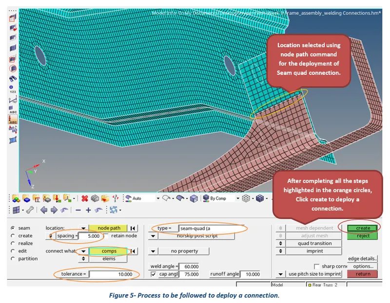
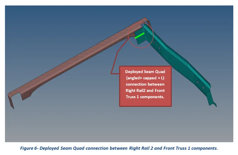
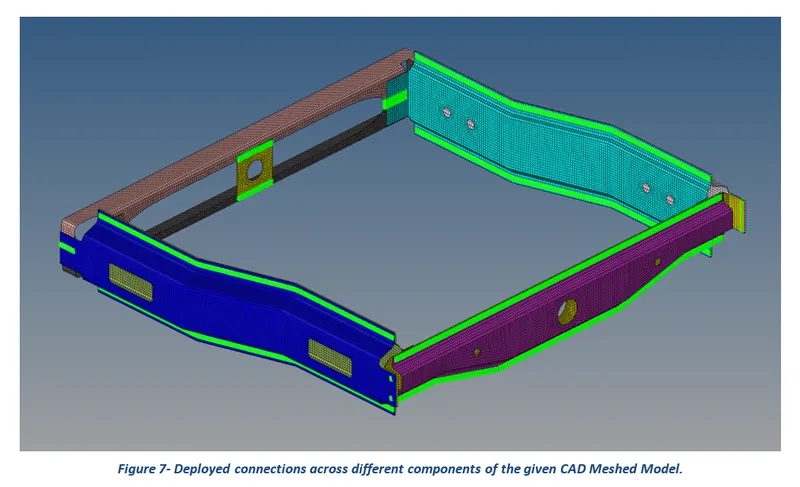
Table 2- Deployed connections across different parts of the given CAD model.
|
Parts |
Connections |
|
Right Rail 2 & Front Truss 1 |
Seam Quad (angled+ capped +L) |
|
Left Rail 2 & front Truss 1 |
Quad Elements |
|
Front Truss 2, Front Truss 1 & Right Rail 1 |
Spotweld with 2 layers and 5mm diameter |
|
Front Truss 2, Front Truss 1 & Left Rail 1 |
Hexa (adhesive) |
|
Rear Truss 2 & Right Rail 2 |
Bolt Connector |
|
Rear Truss 2 & Left Rail 2 |
Bolt Connector |
|
Right Rail 1 & Right Rail 2 |
Spotweld with Rigid elements |
|
Left Rail 1 & Left Rail 2 |
Spotweld with Spring elements |
|
Front Truss 1, Front Truss 2 & Reinf Plate |
Spot (Rigid) |
|
Right Rail 1 & Rear Truss 2 |
Hexa (adhesive) |
4 Conclusion
In conclusion, the main aims of the Week 9 Challenge were to perform geometry clean-up, perform shell meshing as per given quality requirements and deploy the asked different connections across different components of the given CAD model. Moreover, clear the quality failing elements using several operations like ‘rebuild mesh’, ‘mesh smoothing,’ ‘nodes move or paste’, and ‘elements split and join’.