Week 4-1D Element Creation Challenge
Week 4 Challenge: 1D ELEMENT CHALLENGE
Course: HyperMesh for FEA Plastics and Sheet Metal Applications
February 24, 2021
Submitted by: Amanpreet Singh Whan
Supervisor: David Nirmal Paul
List of Figures
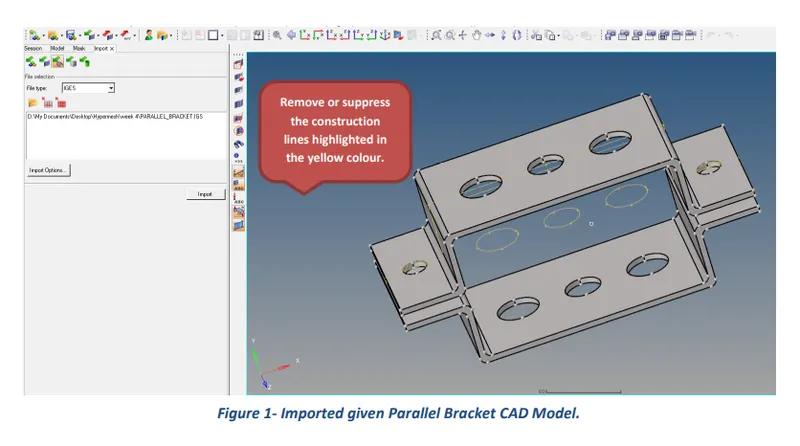
Figure 1- Imported given Parallel Bracket CAD Model.
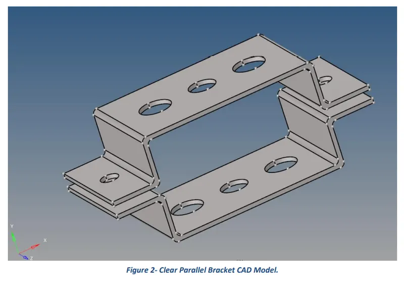
Figure 2- Clear Parallel Bracket CAD Model.
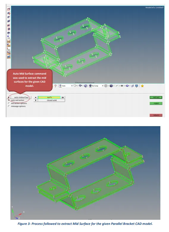
Figure 3- Process followed to extract Mid Surface for the given Parallel Bracket CAD model.
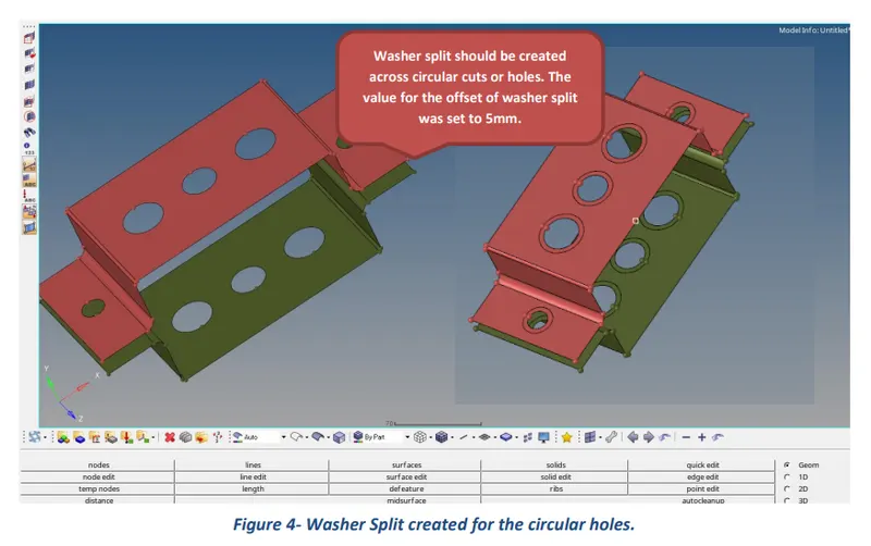
Figure 4- Washer Split created for the circular holes.
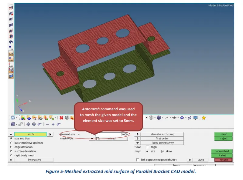
Figure 5-Meshed extracted mid surface of Parallel Bracket CAD model.
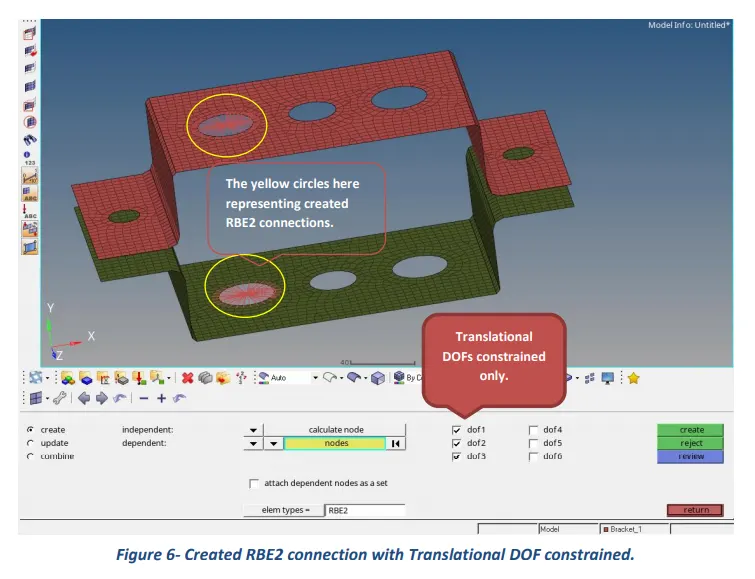
Figure 6- Created RBE2 connection with Translational DOF constrained.
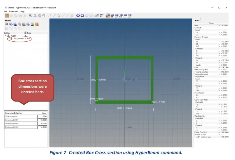
Figure 7- Created Box Cross-section using HyperBeam command.
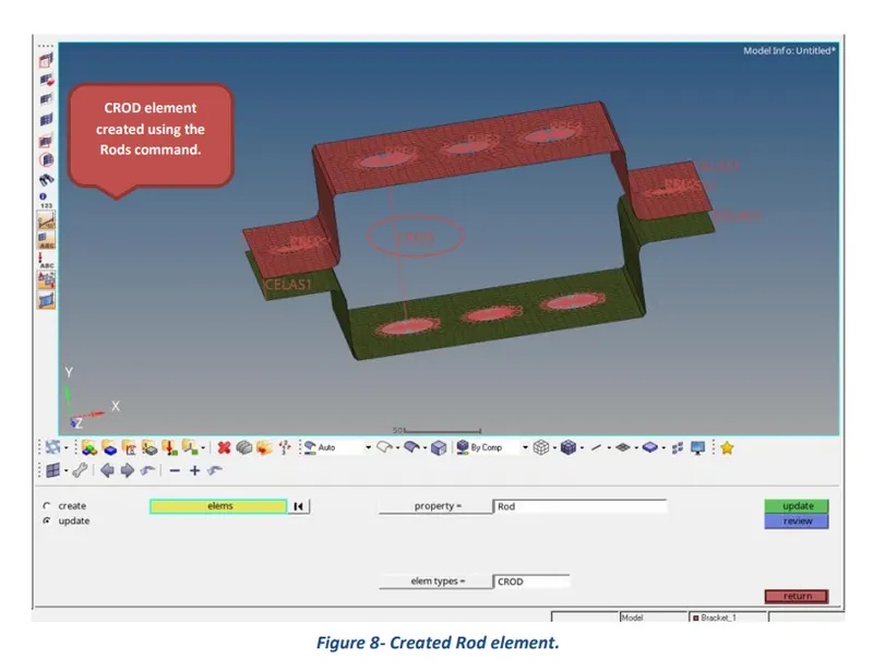
Figure 8- Created Rod element.
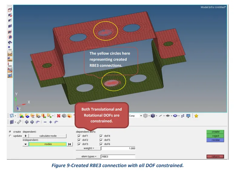
Figure 9-Created RBE3 connection with all DOF constrained. 1
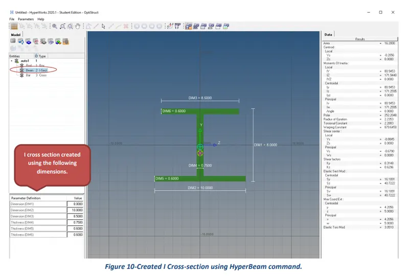
Figure 10-Created I Cross-section using HyperBeam command.
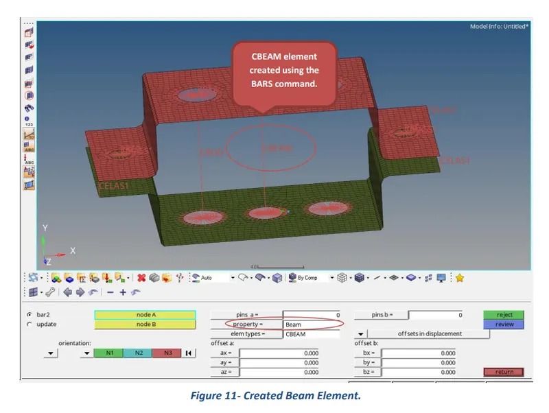
Figure 11- Created Beam Element.
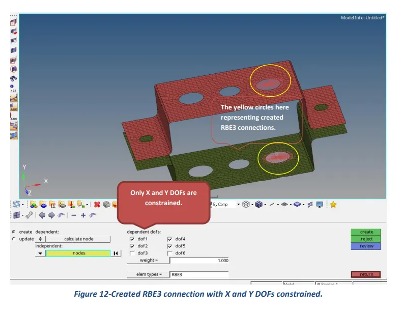
Figure 12-Created RBE3 connection with X and Y DOFs constrained.
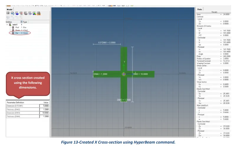
Figure 13-Created X Cross-section using HyperBeam command.
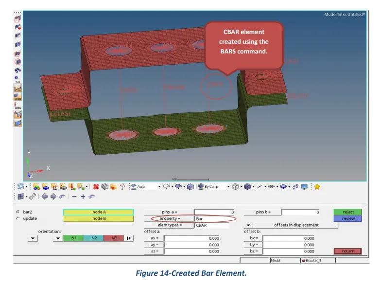
Figure 14-Created Bar Element.
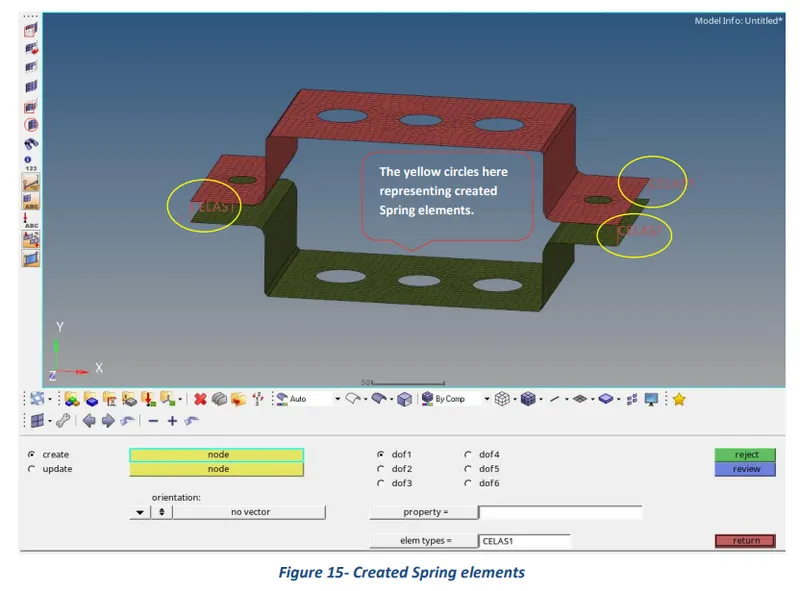
Figure 15- Created Spring elements.
Figure 16- Meshed and created elements scene of the Parallel Bracket model.
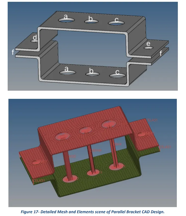
Figure 17- Detailed Mesh and Elements scene of Parallel Bracket CAD Design.
Table of Contents
3.2 Shell Meshing of Parallel Bracket Design
3.3 Creation of Rod, Beam, Bar, Mass, and Spring elements
1 Introduction
HyperMesh is the market-leading, multi-disciplinary finite element pre-processor which manages the generation of the largest, most complex models, starting with the import of CAD geometry to exporting a ready-to-run solver file. HyperMesh supports a wide variety of CAD and solver interfaces, making it a perfect solution for most industry verticals and domains. With its advanced geometry and meshing capabilities, HyperMesh provides an environment for rapid model generation. Generating high-quality mesh quickly is just one of Hyper Mesh’s core competencies. For complex sub-system generation and assembly, HyperMesh has advanced model assembly tools. Modeling of laminate composites is supported by advanced creation, editing, and visualization tools. Design changes can be made easily via mesh morphing and geometry dimensioning.
2 Aims
- Extract or Generate Middle Surface for the components of the given Parallel Bracket CAD Model.
- Perform 2D or Shell Meshing of the given component as per given Mesh Quality Criterion to generate an overall good mesh flow for the entire component.
- Create 1D elements such as Rod element, Beam element, and Bar element across different regions of the extracted mid surface as per challenge requirements.
3 Methodology and Results
The section describes the different stages that were performed using an engineering tool HyperWorks 2020 for the completion of the Week 4 Challenge task. These stages can be further broadly sub-categorized into three key steps, starting from the extraction of Mid Surface, meshing of the mid-surface, and finally carry out deploying of 1D elements across the different regions of the Parallel Bracket CAD model to fulfill the requirements of the challenge.
3.1 Extraction of Mid Surface
After opening the HyperWorks software, the first and foremost step is to import the given CAD model and delete (clear) unnecessary construction lines or planes from the working window. Next click on the Mid surface tool under Geometry Module buttons and use the auto midsurface command to extract mid surface for the given CAD model.
3.2 Shell Meshing of Parallel Bracket Design
Before proceeding with meshing, it is important to create a washer split across circular regions and can be deployed using the washer split command from quick edit options under Geometry Module buttons. The automesh command was used to mesh the extracted mid surface of the Parallel Bracket CAD model. The adopted meshing technique and obtained results are presented in the following pictures.
3.3 Creation of Rod, Beam, Bar, Mass, and Spring elements
What follows hereafter the pictures representing and explaining the procedures that were followed to create various 1D elements across six different regions to fulfill the requirements of the Week 4 Challenge.
|
(Region a) Rod Element: Translational DOF should be constrained with the RBE2 link. Cross Section: Box Dimensions
|
(Region b)
Beam Element: All DOF should be constrained with the RbE3 link. Cross Section: I Dimensions
|
(Region c)
Bar Element: Constraint only X and Y DOFs with RbE3 link. Cross Section: X Dimensions
|
(Regions d & e)
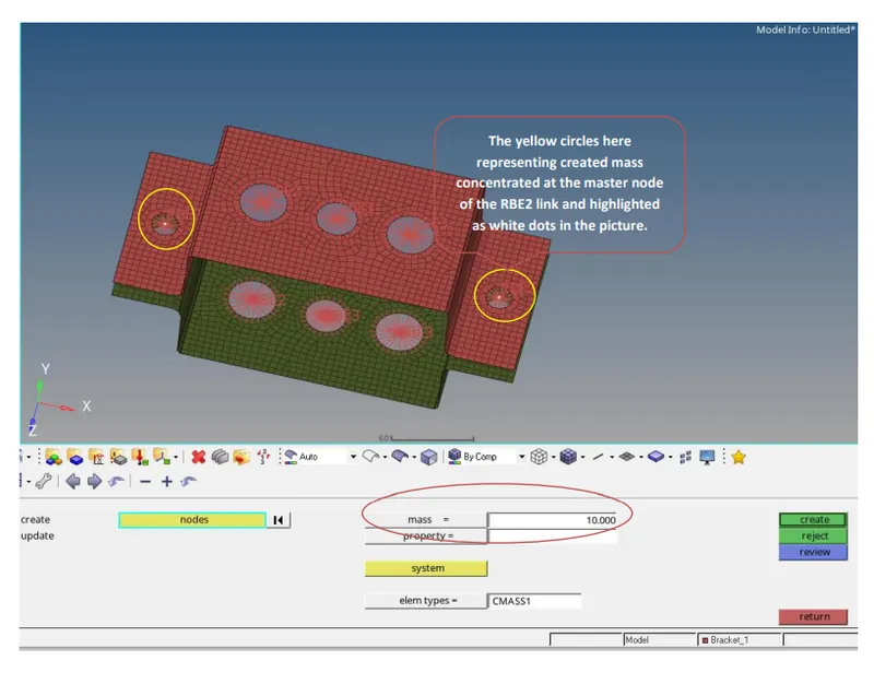
Apply the mass of magnitude 10 with the RBE2 link. |
(Region f)
Join the two components with Spring elements. |
Region a: Creating Rod Element
The creating of a rod element is a three-stage process:
- Create rigid or RBE2 elements using nodes.
- Create Box cross-section of given dimensions using Hyper Beam command.
- Create CROD elements using the ROD command under the 1D commands section.
Region b: Creating Beam Element
The creating of a Beam element is also a three-stage process:
- Create RBE3 elements using nodes.
- Create I cross-section of the given dimensions using the Hyper Beam command.
- Create CBEAM elements using the BARS command under the 1D commands section.
Region c: Creating Bar Element
The creating of a Bar element is also a three-stage process:
- Create RBE3 elements using nodes.
- Create X cross-section of the given dimensions using the Hyper Beam command.
- Create CBAR elements using the BARS command under the 1D commands section.
Regions d & e: Creating Mass of magnitude 10
Region f: Creating Spring elements

4 Conclusion
In conclusion, the main aims of the Week 4 Challenge were to extract the middle surface of the given Parallel Bracket CAD model, perform shell meshing and create different types of 1D Elements across six different regions for the fulfillment of the task.