Week 8
Week 8 Challenge Task: PRACTISING OF THE MORPHING techniques ON THE GIVEN SHEET METAL COMPONENT
Course: Preprocessor for Structural Analysis using ANSA
December 21, 2020
Submitted by: Amanpreet Singh Whan
Supervisor: David Nirmal Paul
Abstract
Morphing enables the analyst to create different variants of mechanical components or assemblies and to rapidly obtain an improved solution without returning to the CAD system for slight changes. The report presents a brief background of morphing techniques and their applications amongst different industries. In addition, the report also presents a detailed procedure that was carried out to morph the given sheet metal component as per instructions of the video lecture for the fulfillment of the Week 8 Challenge task.
Table of Contents
3.1 Import CAD Model and do Geometry Clean-Up
List of Figures
Figure 1-Visualisation of the Box morphing technique.
Figure 2- Visualisation of the Parametric morphing technique.
Figure 3- Visualisation of the Geometry morphing technique.
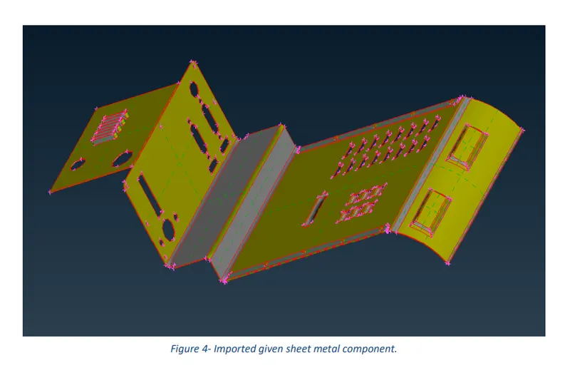
Figure 4- Imported given sheet metal component.
Figure 5-Topo performed and oriented sheet metal component.
Figure 6-Sheet metal component presentation before Length parameters command activated.
Figure 7-Sheet metal component presentation resolution after Length parameters command activated.
Figure 8-Geometry Check-Up command executed and its resulted error.
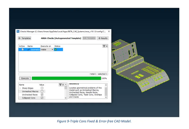
Figure 9-Triple Cons Fixed & Error-free CAD Model.
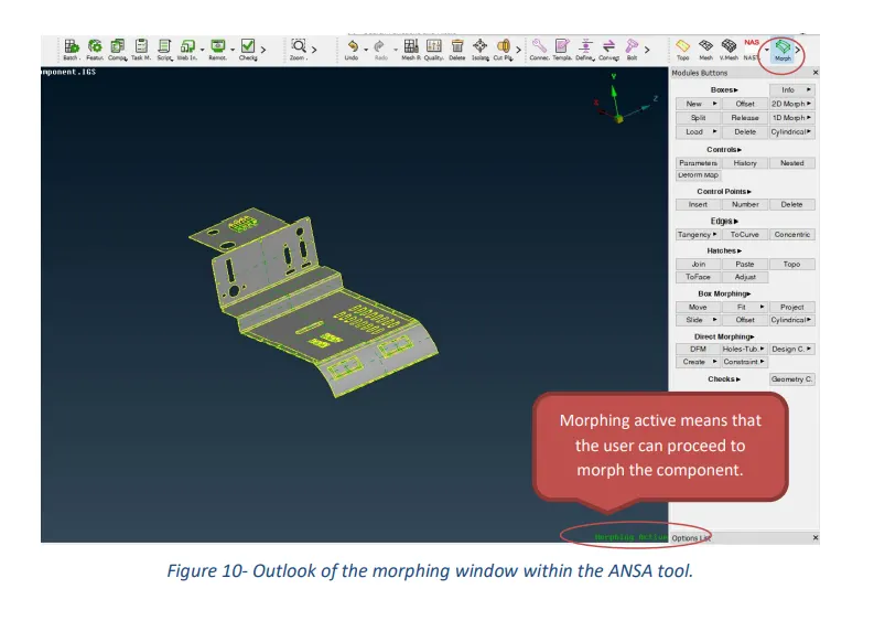
Figure 10- Outlook of the morphing window within the ANSA tool.
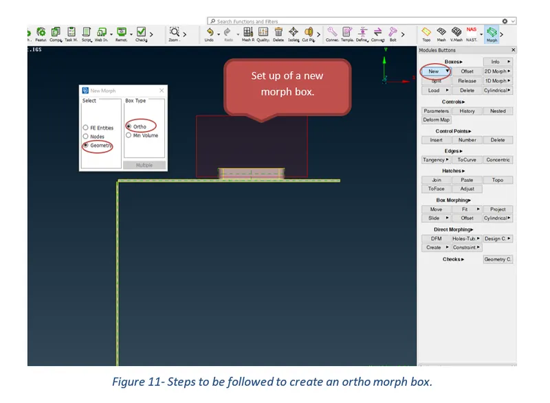
Figure 11- Steps to be followed to create an ortho morph box.
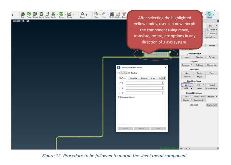
Figure 12- Procedure to be followed to morph the sheet metal component.
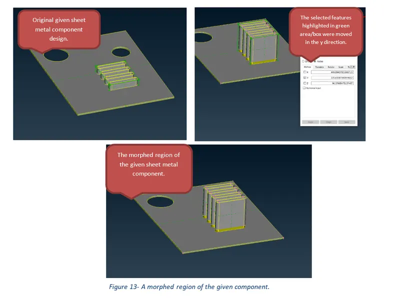
Figure 13- A morphed region of the given component.
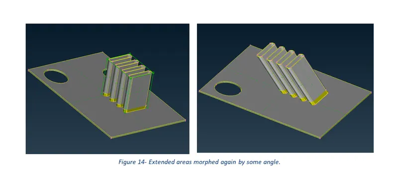
Figure 14- Extended areas morphed again by some angle.
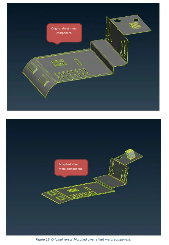
Figure 15- Original versus Morphed given sheet metal component.
1 Introduction
Mesh morphing is an advanced CAE modeling technique used to modify the shape of mechanical parts and assemblies without returning to the CAD system, which is time-consuming and generates unexpected modeling preparation stages. This technique was primarily used in the music video and film industry in the early 90s but rapidly evolved to technical applications, such as modeling algorithms applied in the automotive industry, aerospace industry, biomechanics, computer integrated manufacturing, and re-engineering. Morphing capabilities were introduced in powerful CAE pre-processing systems such as Hypermorph (Altair Engineering), ANSA (BETA CAE System), ANSYS Paramesh (ANSYS Inc.), where specialized modules are now tested and enhanced, pointing out the importance of this modelling technique for the industry. In the automotive sector, morphing techniques can be found to be used in conversion of sedan models into hatchback models, optimisations of subframe assemblies like a front cradle, etc.
Based on different solid modelling representations, the generally used morphing methods include parameterization-based morphing, scaling coupled with Boolean difference morphing method, octree-based morphing, and mesh-based morphing.
ANSA is a pre-processing tool for Finite Element Analysis. “Morphing Tool” is the morphing function ANSA provides. The Morphing Tool modifies the shape of a mesh/ CAD model by creating and handling special entities called Morphing Boxes. The Morphing Box is the basic entity of the Morphing Tool. The Morphing Box can include line, shell or solid elements, or any combination of them. By changing the shape of this box, the included elements will change their shape and position accordingly. The shape of the morphing box is controlled by Control Points residing at the corners and on the edges of Morphing Boxes. Thus, the parameters can be defined as translation distances of the Control Points along with three coordinate directions. After defining parameters associated with actions of the Control Points, the objects can be morphed “parametrically”.
The functions of the Morphing tool can be used to efficiently re-shape both FE and/or Geometry based models. The following are the different methods that can be chosen to morph a solid or FE model in ANSA software.
Domain (Box) Morphing
Domain or Box Morphing is performed via boxes that are created around a part of an assembly that the user intends to morph. The movement of the Morphing boxes control points defines the morphing operations on the entities inside the Morph box. This type of Morphing can be applied to both FE and Geometry based models.
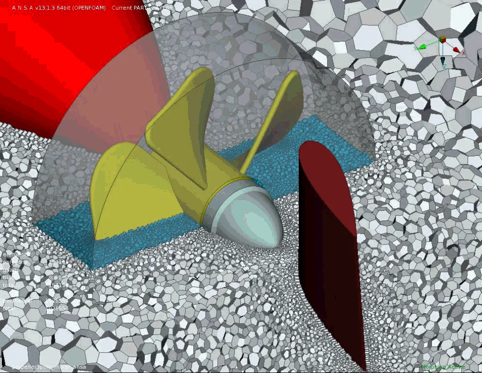
Figure 1-Visualisation of the Box morphing technique.
Direct Morphing
Direct morphing features gives the user ability to efficiently modify a part locally without having to create Morphing boxes. This method is extremely useful in creating local modifications on single parts. Creation of depressions, surface fitting certain FE part features to new target geometry, moving selected features along the contour of a surface, and the ability to freeze rigid elements during the morphing process are some of the direct morphing abilities.
Parametric Morphing
The desired morphing actions can be saved as parameters that can be accessed in batch mode. Users can enforce desired shape changes by changing the numerical input value for the appropriate parameter. This method of morphing is highly utilized for coupling the morphing operations to an external optimizer. The scripting capability can be used in conjunction with ANSA’s parametric morphing functionality to deliver faster DOE models.
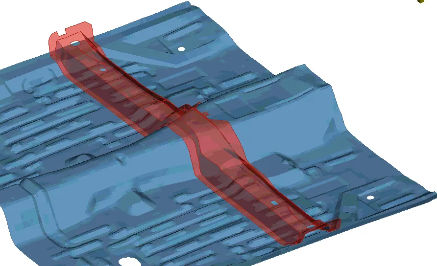
Figure 2-Visualisation of the Parametric morphing technique.
Geometry Morphing
ANSA brings to the CAE world it is a ‘one of a kind’ tool for CAD geometry morphing. This pioneering concept allows the user to utilize the inventory of all the familiar FE morphing functions to perform equivalent operations in a CAD environment on geometric entities.
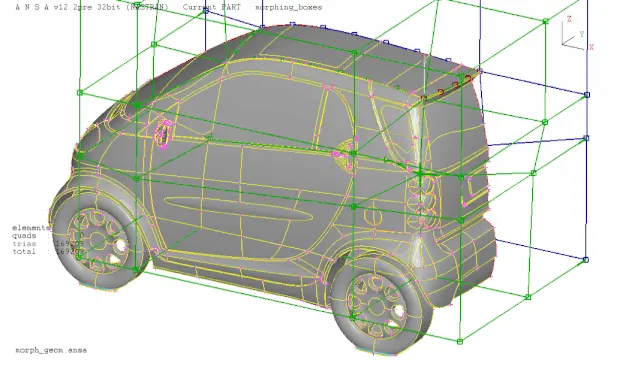
Figure 3-Visualisation of the Geometry morphing technique.
2 Aims
- Check and fix all the geometry errors of the given Model for Geometry Clean-up purposes.
- Practicing all the morphing techniques that were taught for the given sheet metal component.
3 Methodology and Results
The section describes the different stages that were performed using an engineering tool, ANSA Pre-Processor for the completion of the Week 8 Challenge sheet metal component project. ANSA Pre Processor is an advanced computer-aided engineering tool extensively used for FEA (Finite Element Analysis) and CFD (Computational Fluid Dynamics) analysis in the automotive and aerospace industry. ANSA pre-processor is a CAE software developed by BETA CAE Systems and follows a strict workflow when numerically solving a given problem.
3.1 Import CAD Model and do Geometry Clean-Up
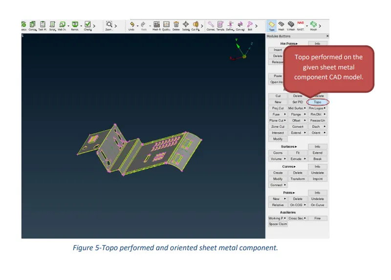
After opening the ANSA Pre-processor software, the first and the foremost step is to import the CAD geometry and perform topology using the topo command in the faces section of Topo Module Buttons for the entire model.
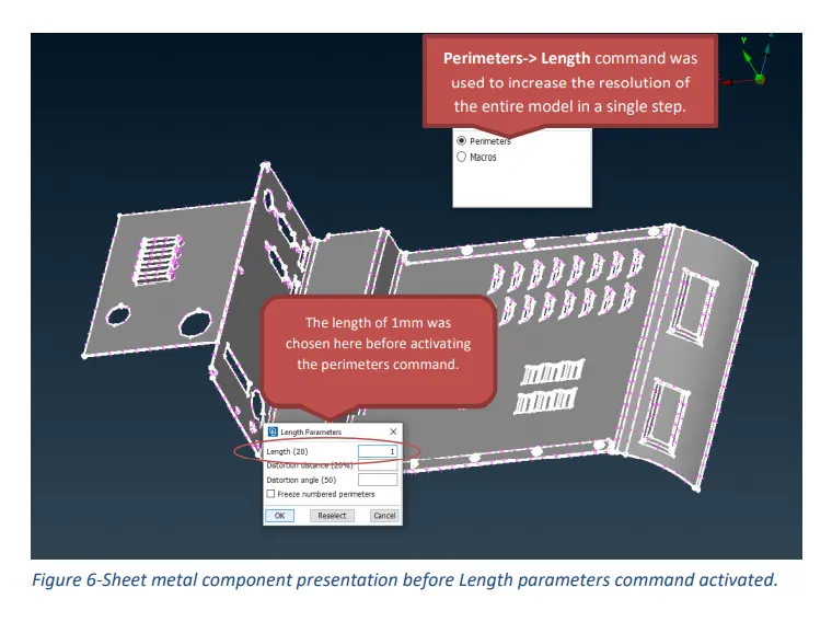
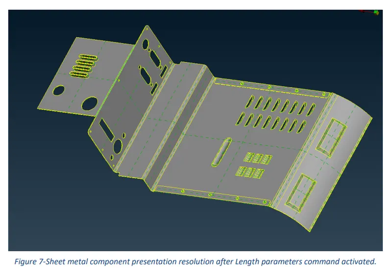
The model can be refined either using Auxiliaries-> fine in Topo Module Buttons or by simply setting a value of length for the entire model in the Perimeters section of Mesh Module Buttons. Considering the complexity of the fine operation, Mesh perimeters-> Length was chosen to be the easiest and preferable choice.
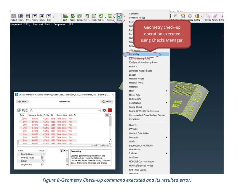
In the next step, go to the Checks Manager and select geometry from the options list. The main function of the Checks geometry is to locate geometrical issues such as unmeshed macros, unchecked faces, needle faces, collapsed cons, triple cons, and cracks. Even though most of these errors can be easily eliminated using the Auto-Fix command but issues concerning triple cons must be fixed manually by releasing Cons or Hot-points (nodes) and joining cons/ nodes back again using the topo command. Before executing the Checks geometry operation, make sure to turn on the most essential above stated geometry issues.
What follows hereafter is the set of images showing different results obtained before and after the completion of geometry clean-up for the given model using ANSA Pre-Processor software.
3.2 Morphing
What follows hereafter is a set of images showing the process that was followed to morph the sheet metal component and the obtained results as instructed in the video lecture.
4 Discussion
ANSA Pre-Processor was used to perform morphing as per instructions of the video lecture for the successful completion of the Week 8 Challenge task. To fulfil the requirements of the challenge, Geometry clean-up and morphing was performed, and the obtained results are presented in the figures shown above.
In figure 8, it can be clearly seen that the provided CAD component had multiple errors such as needle faces, cracks, unchecked faces and triple cons which were fixed using both manual and automatic methods.
Figures 11 and 12 illustrate the procedure to be carried out for the morphing of the given sheet metal component. The ortho (geometry) box morphing method was used to morph the different regions of the given component. Figure 15 shows all the regions where the morphing has been performed to fulfil the requirements of the challenge.
5 Conclusion
In conclusion, the main aim of the challenge was to do a geometry clean-up and perform morphing as per instructions of the video lecture.
6 Learning Outcomes
Throughout this challenge, I have gained knowledge of different commands that are required to carry out the morphing of a sheet metal component. I have also come to know about the different morphing techniques that are used in several industrial sectors.
References
https://www.ansa-usa.com/solutions/morphing/
Link to access the completed task:
https://drive.google.com/file/d/1Ez6w7307nBIJw2CRFzICUtQ2Ouop7fMv/view?usp=sharing