Week 2- 2R Robotic Arm Challenge
Course: MATLAB for Mechanical Engineers
Challenge: 2R Robotic Arm Challenge
Submitted By: Amanpreet Singh Whan
1 Aim:
The aim of the week 2 challenge is to write a program in MATLAB to simulate the forward kinematics of a 2R Robotic Arm
2 Theory and Governing Equations:
A robotic arm is a type of mechanical arm, usually programmable, with similar functions to a human arm; the arm may be the sum of the mechanism or may be part of a more complex robot The links of such a manipulator are connected by joints allowing either rotational motion (such as in an articulated robot) or translational (linear) displacement. The links of the manipulator can be considered to form a kinematic chain. The terminus of the kinematic chain of the manipulator is called the end effector and it is analogous to the human hand. However, the term "robotic hand" as a synonym of the robotic arm is often proscribed.
A pick and place robot arm is used to ease the process of moving materials and supplying the motion required in the manufacturing processes. The transfer process of the materials is usually being accomplished, using manpower and as the transfer process is repeated for a period, it can cause injuries to the operator. The robot arm prevents injuries and increases the efficiency of the work, reducing human being errors that higher cost time and martial.
Most robot manipulators found in industrial operations are controlled by PID algorithms independently at each joint. There are many control techniques used for controlling the robot arm.
Robot Specification
A two degree of the freedom robot arm is described in Figure(1) which consists primarily of two links with the following specifications in OXY coordinates:
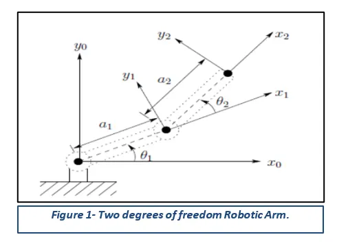
L1 = 1 m is the length of the first link.
L2 = 0.5 m is the length of the second link.
theta_1 = the rotation angle of the first link.
theta_2 = the rotation angle of the second link.
Forward Kinematics: The Forward kinematics of a robotic arm is determined by a group of parameters called Denavit-Hartenberg (DH) parameters which are used for deriving the homogenous transformation matrices between the different frames assigned on the robot arm structure.
3 Objectives:
The objectives of the week 2 challenges are as follows:
- Simulate the forward kinematics of a 2R Robotic Arm at different rotation angles of theta_1 and theta_2.
- Create an animation file from the obtained results using MATLAB.
4 Body of the Content:
MATLAB (an abbreviation of "MATrix LABoratory") is a proprietary multi-paradigm programming language and numeric computing environment developed by MathWorks. MATLAB allows matrix manipulations, plotting of functions and data, implementation of algorithms, creation of user interfaces, and interfacing with programs written in other languages. Although MATLAB is intended primarily for numeric computing, an optional toolbox uses the MuPAD symbolic engine allowing access to symbolic computing abilities. An additional package, Simulink, adds graphical multi-domain simulation and model-based design for dynamic and embedded systems.
In total three MATLAB codes were written to fulfill the requirements of the Week 2 challenge and are attached in the following figures. In addition, the animation created from the final written code is attached as well.
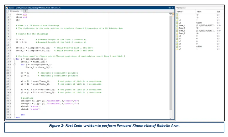
Code 1: The first MATLAB code written to simulate the 2R Robotic Arm simulator is attached in the following figure 2.
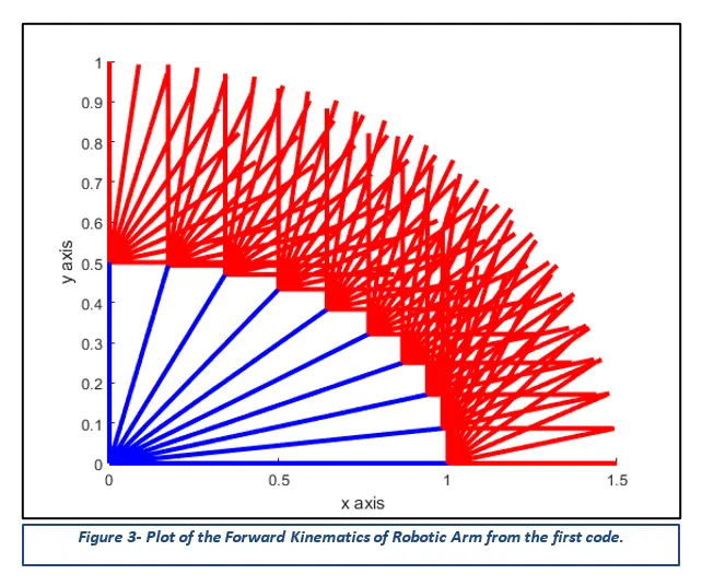
From Figure 3, it can be observed that the first code has combined and mapped all the positions of both the Links 1 and 2 onto one single graph which does not only look a bit strange but also fails to meet the requirements for the challenge of creating an animation file.
Code 2: The second MATLAB code written to simulate the 2R Robotic Arm simulator is attached in the following figure 4.
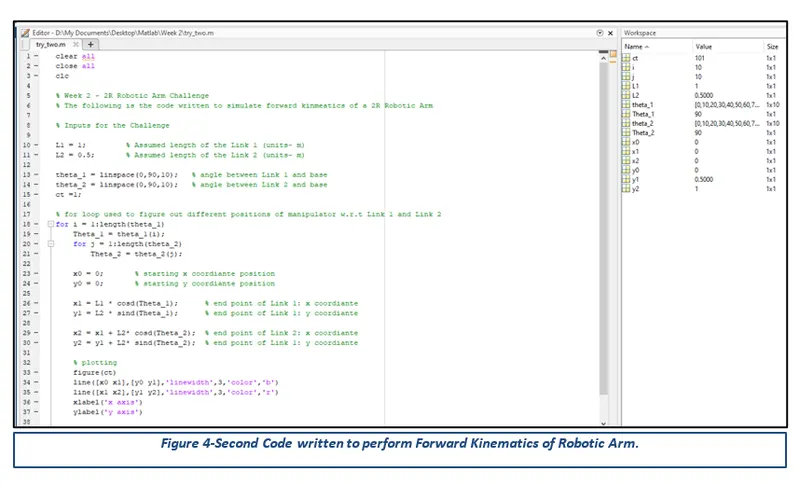
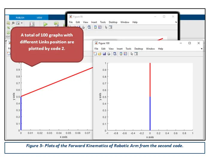
From Figure 5, it can be observed that the second code has created 100 Graphs with different Links positions. Even though the code has generated the correct graphs, it still not has fulfilled the requirements of creating an animation simulating the forward kinematics of the 2R Robotic Arm. One solution is to save all these graphs as images in a folder and then stitch them up to create an animation using the Image Magick software.
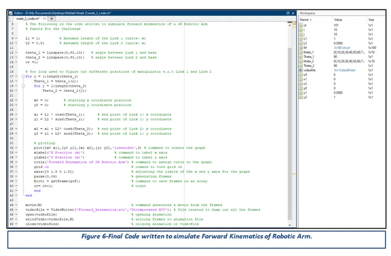
Code 3: The third and final code written involves the usage of inbuilt MATLAB commands to create an animation file as per the challenge requirements and is attached in the following figure.
Youtube Link for the 2R Robotic Arm Animation:
5 Conclusion:
In conclusion, the main aim of the week 2 challenge is to write a MATLAB program to simulate the forward kinematics of a 2R Robotic Arm. In addition, create an animation using the MATLAB in-built commands.
6 Appendix:
Code 1
clear all
close all
clc

% Week 2 - 2R Robotic Arm Challenge
% The following is the code written to simulate forward kinematics of a 2R Robotic Arm

% Inputs for the Challenge

L1 = 1;         % Assumed length of the Link 1 (units- m)
L2 = 0.5;       % Assumed length of the Link 2 (units- m)

theta_1 = linspace(0,90,10);   % angle between Link 1 and base
theta_2 = linspace(0,90,10);   % angle between Link 2 and base

% for loop used to figure out different positions of manipulator w.r.t Link 1 and Link 2
for i = 1:length(theta_1)
    Theta_1 = theta_1(i);
    for j = 1:length(theta_2)
        Theta_2 = theta_2(j);

    x0 = 0;       % starting x coordiante position
    y0 = 0;       % starting y coordiante position

    x1 = L1 * cosd(Theta_1);      % end point of Link 1: x coordiante
    y1 = L2 * sind(Theta_1);      % end point of Link 1: y coordiante

    x2 = x1 + L2* cosd(Theta_2);  % end point of Link 2: x coordiante
    y2 = y1 + L2* sind(Theta_2);  % end point of Link 1: y coordiante

    % plotting
    line([x0 x1],[y0 y1],'linewidth',3,'color','b')
    line([x1 x2],[y1 y2],'linewidth',3,'color','r')
    xlabel('x axis')
    ylabel('y axis')

    end
end
Code 2
clear all
close all
clc

% Week 2 - 2R Robotic Arm Challenge
% The following is the code written to simulate forward kinematics of a 2R Robotic Arm

% Inputs for the Challenge

L1 = 1;         % Assumed length of the Link 1 (units- m)
L2 = 0.5;       % Assumed length of the Link 2 (units- m)

theta_1 = linspace(0,90,10);   % angle between Link 1 and base
theta_2 = linspace(0,90,10);   % angle between Link 2 and base
ct =1;

% for loop used to figure out different positions of manipulator w.r.t Link 1 and Link 2
for i = 1:length(theta_1)
    Theta_1 = theta_1(i);
    for j = 1:length(theta_2)
        Theta_2 = theta_2(j);

    x0 = 0;       % starting x coordiante position
    y0 = 0;       % starting y coordiante position

    x1 = L1 * cosd(Theta_1);      % end point of Link 1: x coordiante
    y1 = L2 * sind(Theta_1);      % end point of Link 1: y coordiante

    x2 = x1 + L2* cosd(Theta_2);  % end point of Link 2: x coordiante
    y2 = y1 + L2* sind(Theta_2);  % end point of Link 1: y coordiante

    % plotting
    figure(ct)
    line([x0 x1],[y0 y1],'linewidth',3,'color','b')
    line([x1 x2],[y1 y2],'linewidth',3,'color','r')
    xlabel('x axis')
    ylabel('y axis')

    ct= ct+1;
    end
end
Final Code
clear all
close all
clc

% Week 2 - 2R Robotic Arm Challenge
% The following is the code written to simulate forward kinmeatics of a 2R Robotic Arm

% Inputs for the Challenge

L1 = 1;         % Assumed length of the Link 1 (units- m)
L2 = 0.5;       % Assumed length of the Link 2 (units- m)

theta_1 = linspace(0,90,10);   % angle between Link 1 and base
theta_2 = linspace(0,90,10);   % angle between Link 2 and base
ct =1;

% for loop used to figure out different positions of manipulator w.r.t Link 1 and Link 2
for i = 1:length(theta_1)
    Theta_1 = theta_1(i);
    for j = 1:length(theta_2)
        Theta_2 = theta_2(j);

    x0 = 0;       % starting x coordiante position
    y0 = 0;       % starting y coordiante position

    x1 = L1 * cosd(Theta_1);      % end point of Link 1: x coordiante
    y1 = L2 * sind(Theta_1);      % end point of Link 1: y coordiante

    x2 = x1 + L2* cosd(Theta_2);  % end point of Link 2: x coordiante
    y2 = y1 + L2* sind(Theta_2);  % end point of Link 1: y coordiante

    % plotting
    plot([x0 x1],[y0 y1],[x1 x2],[y1 y2],'linewidth',3) % command to create the graph
    xlabel('X Position (m)')              % command to label x axis
    ylabel('Y Position (m)')              % command to label y axis
    title('Forward Kinematics of 2R Robotic Arm') % command to assign title to the graph
    grid on                                       % comand to turn grid on
    axis([0 1.5 0 1.5])                           % adjusting the limits of the x and y axis for the graph
    pause(0.04)                                   % generating frames
    M(ct) = getframe(gcf);                        % command to save frames in an array
    ct= ct+1;                                     % count
    end
end

movie(M)                                          % command generates a movie from the frames
videofile = VideoWriter('Forward_kinematics.avi','Uncompressed AVI'); % file created to dump out all the frames
open(videofile)                                   % opening animation
writeVideo(videofile,M)                           % writing frames to animation file
close(videofile)                                  % closing animation or videofile