Week-7 Head Impact
Week 7 Challenge: Pedestrian Head Impact Challenge
Course: LS-DYNA for Structural Mechanics/ FEA
Submitted by: Amanpreet Singh Whan
Supervisor: Tholkappiyan D
August 08, 2021
Table of Contents
1 Introduction
LS-DYNA is an advanced general-purpose multiphysics simulation software package developed by the former Livermore Software Technology Corporation (LSTC), which was acquired by Ansys in 2019. While the package continues to contain more and more possibilities for the calculation of many complex real-world problems, its origins and core competency lie in highly nonlinear transient dynamic finite element analysis (FEA) using explicit time integration. LS-DYNA is used by the automobile, aerospace, construction and civil engineering, military, manufacturing, and bioengineering industries.
Accidents involving pedestrian impact have been targeted as an area of automobile safety worthy of study and research. Among the many approaches to this problem is to design automobiles for less severe pedestrian injuries. Of particular concern are injuries to the pedestrian's head caused by impact on the automobile body. Redesign automobiles for pedestrian safety is obviously a costly undertaking. However, it is reasonable to expect that incorporating simple modifications into existing designs can reduce the number and severity of pedestrian head injuries quickly and at a low cost. New designs can be proposed, and prototypes built and tested using established techniques. However, in order to make pedestrian head injury mitigation more appealing, a low-cost design technique must be found. Therefore, finite element analysis (FEA) is applied to the mitigation of pedestrian head injury. Design prototypes are modeled and impacted by a simulated pedestrian head form using readily available finite element code, namely, ANSYS and DYNA3D. Results are analyzed, animations studied, and further design improvements proposed and tested. This may be followed by verification with a test impact of the new prototype. FEA promises to make pedestrian head injury mitigation appealing, cost-effective, and be incorporated into automobile design
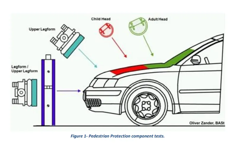
Pedestrian protection CAE is a part of vehicle safety engineering from a crash perspective. In pedestrian protection, we look for imparting minimum injury to the head, upper leg (thigh), and lower leg (including knee) in case of an accident with a human subject. These tests are usually done at a lower velocity from 20-40 kph as accidents tend to result in more severe circumstances above these velocities and braking in case of an accident often results in collision at low velocities.
The purpose of the Week 7 challenge is to perform the Head Impact Simulation and calculate the HIC value in the LS Pre-Post for three different scenarios, a) impact of a simple head impact with the Rigid wall b) impact of the given Head form with the Rigid wall and c) impact of the head form with the Hood. Also, compare the stress/ strain and acceleration plots for the different scenarios mentioned above.
2 Aims
- Create simulation setups to perform impact of the simple head with the rigid wall, impact of head form with the rigid wall, and impact of the head form with the given Hood model.
- Analyze and compare stress/ strain and other results obtained from the simulations performed for the different scenarios.
- Calculate HIC values for three different scenarios using LS Pre-Post.
3 Methodology
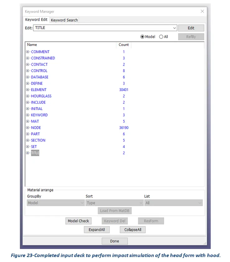
The section describes different stages that were performed to set up the simulation file using an engineering tool LS-DYNA for the completion of the Week 7 Challenge task. These stages can be broadly categorized into creating an input deck containing different cards such as contact, control, database, element, hourglass, initial (velocity), keyword, MAT, node, part, section, and title.
Since LS-DYNA does not have a default system of units, therefore, the user needs to input material properties and physical dimensions according to a consistent system of units as per their choice. Considering the challenge requirements of simulating an impact test of head form with the Hood model, kg mm ms were assumed to be the most appropriate units.
What follows hereafter is the set of images representing the process followed to create different cards and values assigned to their key parameters.
Contact:
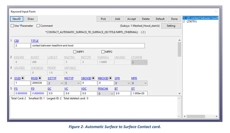
The keyword CONTACT provides a way of treating interaction between disjoint parts. Automatic Surface to Surface Contact was defined for the challenge purposes.
Control:
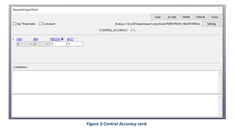
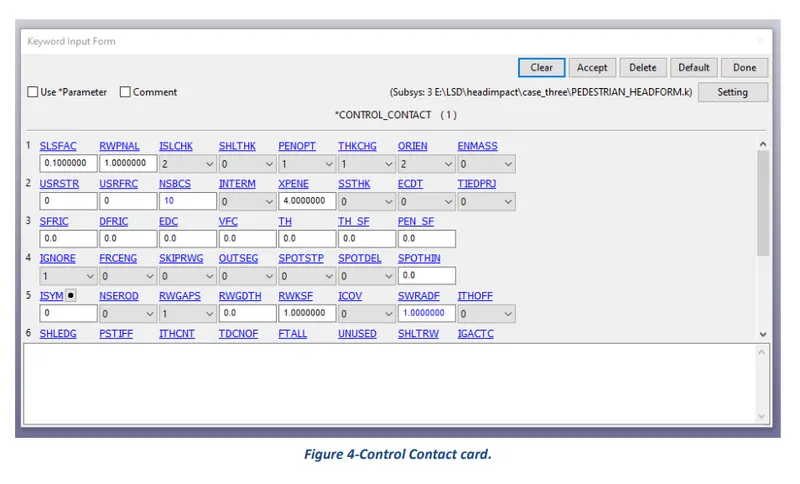
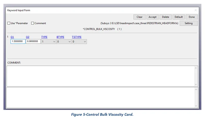
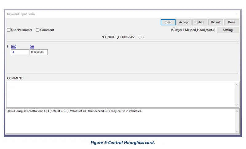
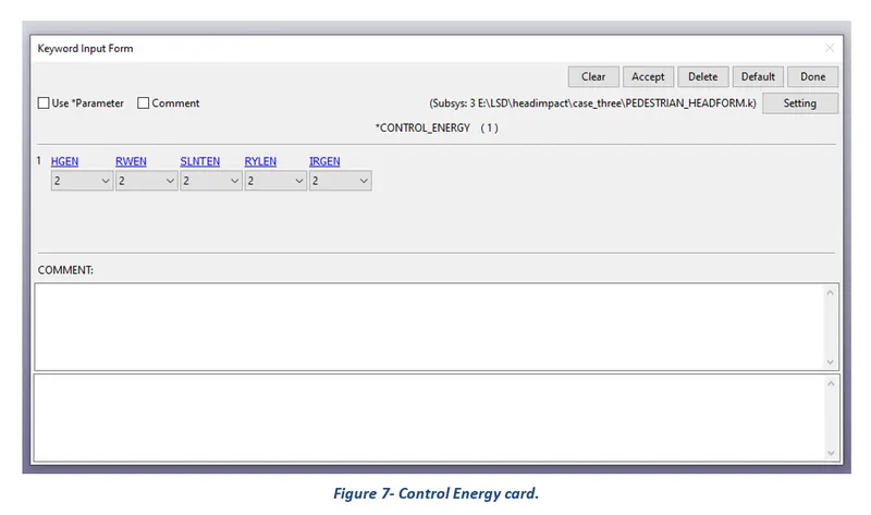
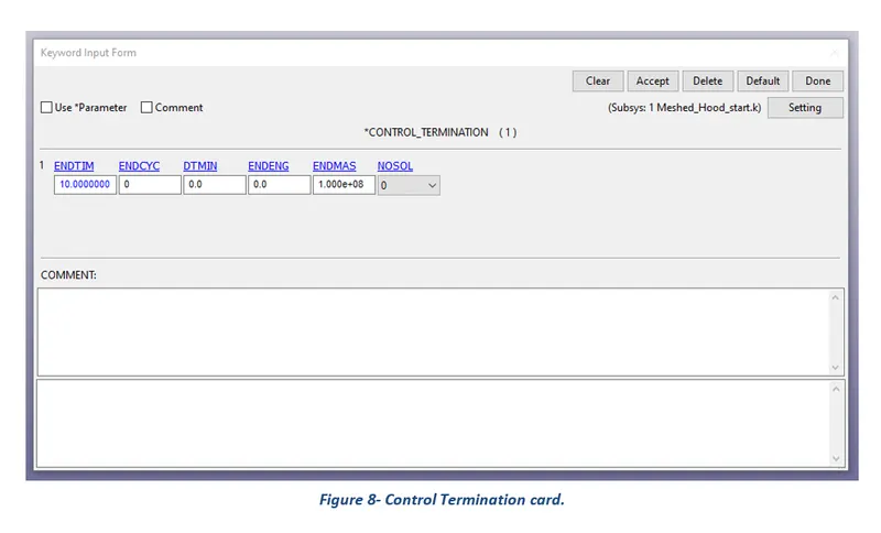
The keyword control cards can be used to change defaults. The control accuracy, contact, hourglass, energy, output, timestep and control termination cards were created for the challenge purposes.
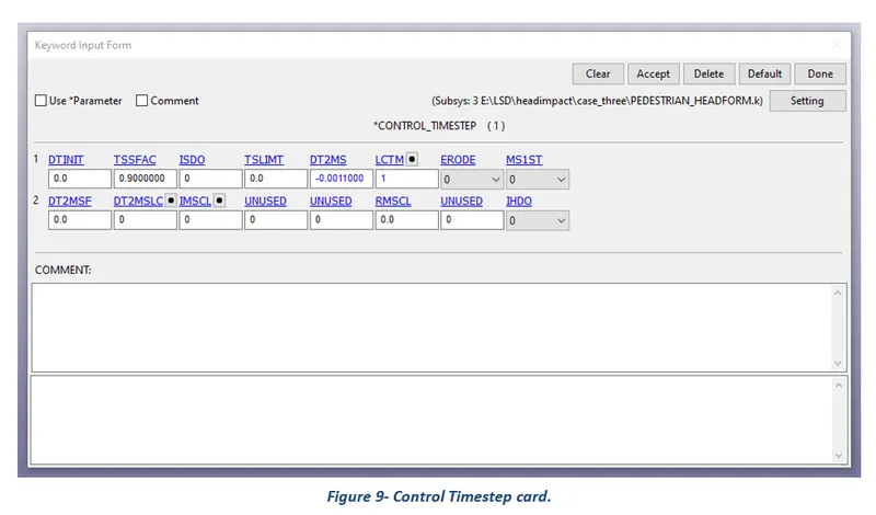
Database:
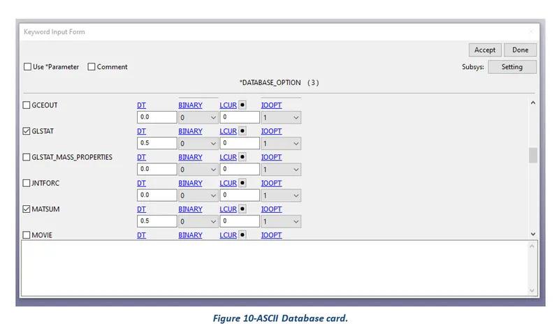
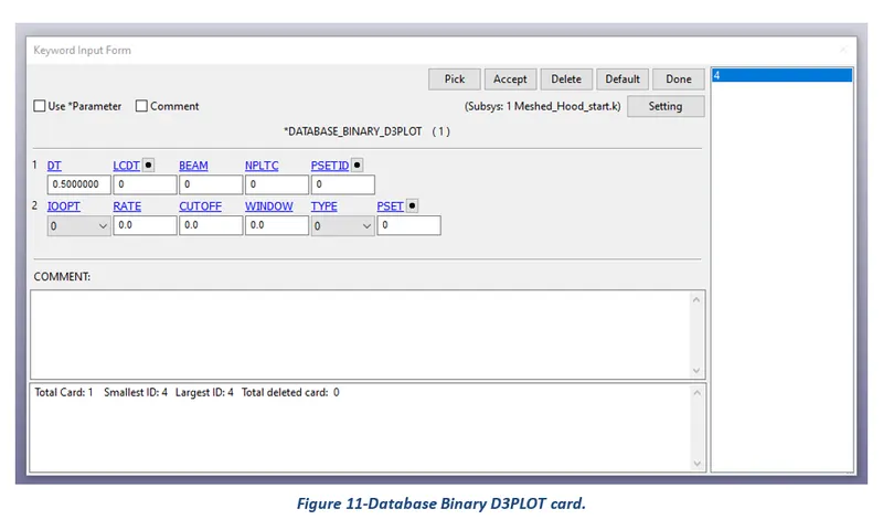
The database definitions are necessary to obtain output files containing results information. The binary D3Plot, Extent Binary, and ASCII options were selected for the challenge purposes.
Define:
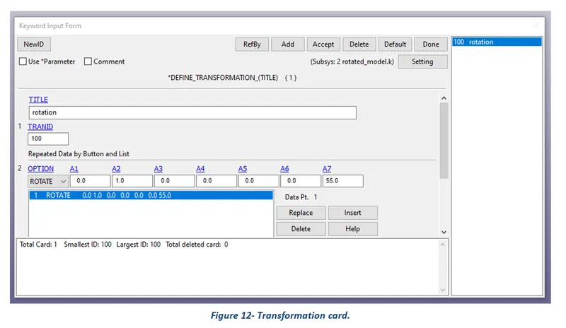
The keyword DEFINE provides a way of defining boxes, coordinate systems, load curves, functions, tables, transformations, and orientation vectors. The transform option was selected, and the assigned value for rotation is presented in the following card.
Hourglass:
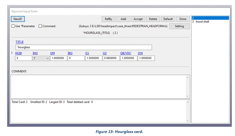
Hourglass (HG) modes are nonphysical, zero-energy modes of deformation that produce zero strain and no stress. Hourglass modes occur only in under-integrated (single integration point) solid, shell, and thick shell elements.
Include:
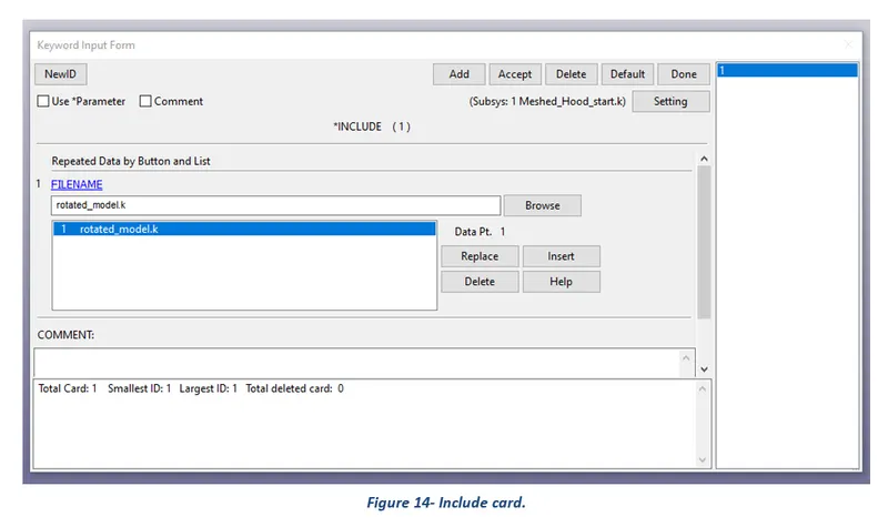
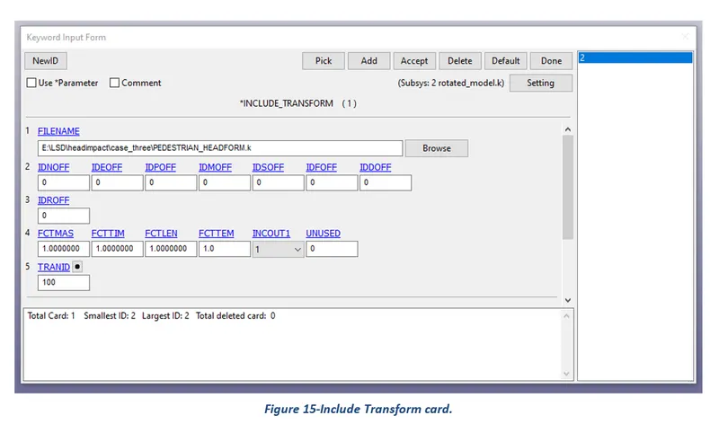
The keyword INCLUDE provides a means of reading independent input files containing model data. The file contents are placed directly at the location of the include line. For the challenge purposes, include and include transform cards were created.
Initial:
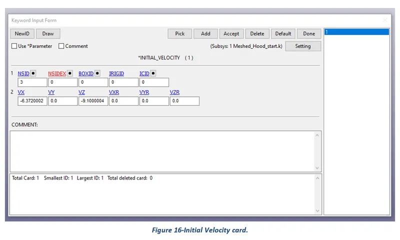
The keyword INITIAL provides a way of initializing velocities and detonation points. The velocity option was selected, and the assigned value of velocity is presented in the following card.
Mat:
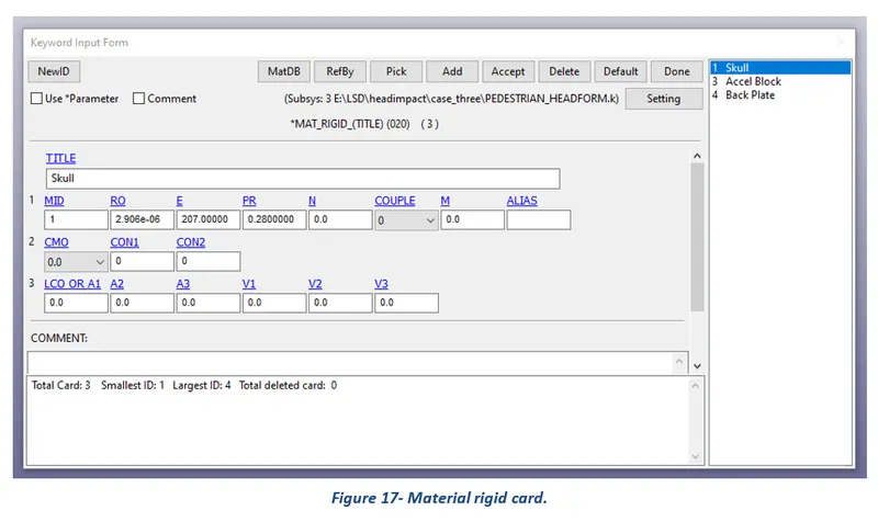
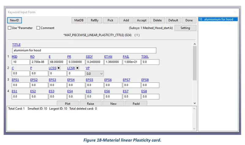
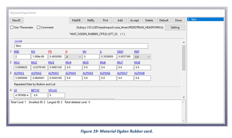
The keyword MAT helps in defining and assigning of different types of materials to a part as per requirements. For this challenge MAT 20 Rigid, MAT 24 Piecewise Linear Plasticity, and MAT 077 Hyper-Elastic Ogden Vulcanised rubber were selected. The given values assigned to material card parameters are presented in the following card.
Section:
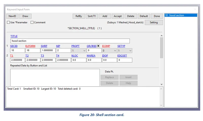
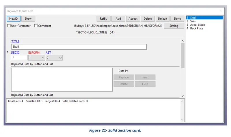
Under section the element formulation, integration rule, nodal thicknesses, and cross-sectional properties are defined. Solid and shell sections were created as per challenge requirements and assigned values for their parameters are presented in the following picture.
Part:
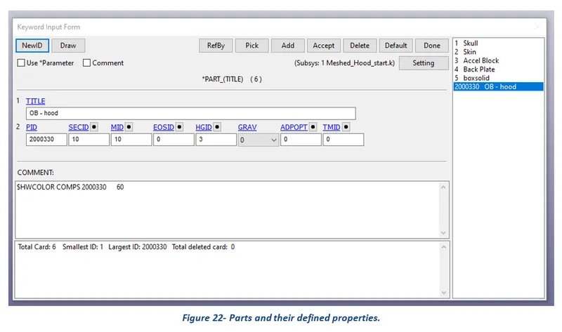
Here define combine material information, section properties, hourglass type, thermal properties, and a flag for part adaptivity.
4 Results
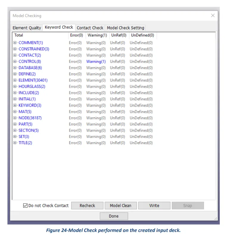
After setting up the input deck and saving the file. K format, the first and foremost step is to perform a model check and then run the simulation using LS-Run software. Once normal termination is achieved, the results can be viewed and analyzed using LS Pre-Post software.
Results of impact of the simple head with a rigid wall.
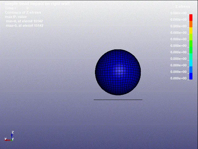
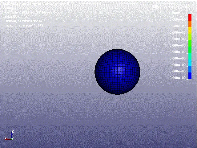
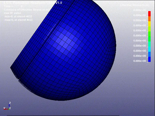
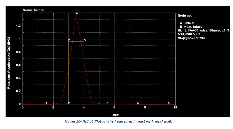
Results of impact of head form with a rigid wall.
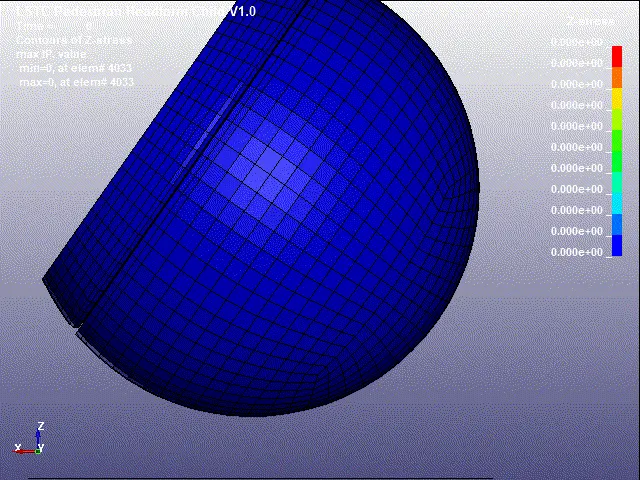
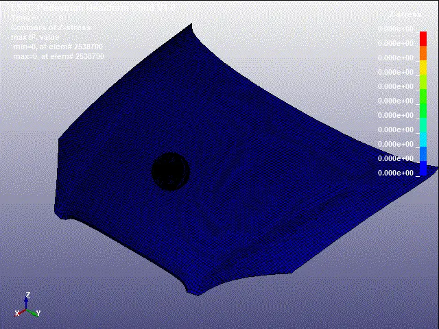
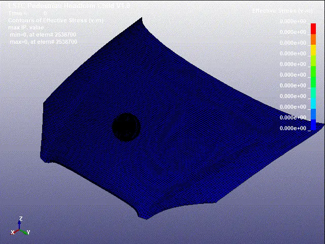
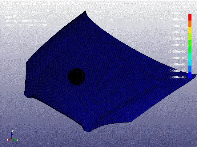
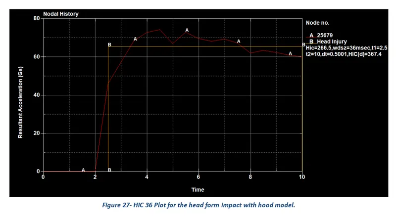
Results of impact of head form with the hood model.
Manual calculation of HIC (head injury criterion)
The head injury criterion (HIC) is a measure of the likelihood of head injury arising from an impact. The HIC can be used to assess safety-related to vehicles, personal protective gear, and sports equipment. Normally the variable is derived from the measurements of an accelerometer mounted at the center of mass of the crash test dummy’s head when the dummy is exposed to crash forces.
It is defined as:
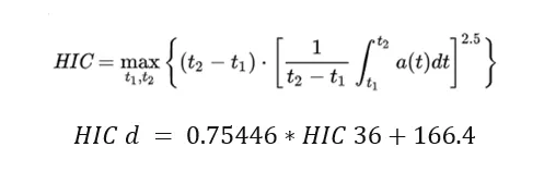
where t1 and t2 are the initial and final times (in seconds) chosen to maximize HIC, and ‘a’ acceleration is measured in gs (standard gravity acceleration). The time duration, t2 – t1, is limited to a maximum value of 36 ms or usually 15 ms.
This means that the HIC includes the effects of head acceleration and the duration of the acceleration. Large accelerations may be tolerated for very short times. At a HIC of 1000, there is an 18% probability of a severe head injury, a 55% probability of a serious injury, and a 90% probability of a moderate head injury to the average adult.
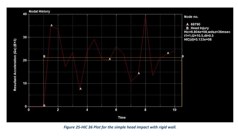
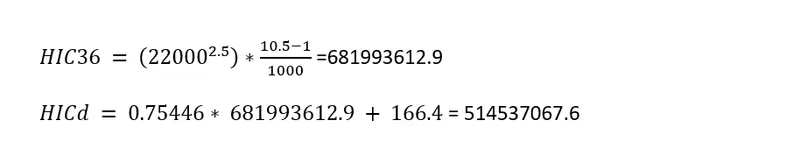
Case 1)- Calculation of HIC36 & HIC d for the impact of the simple head with rigid wall
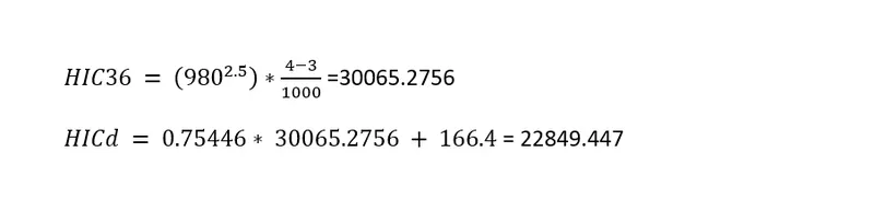
Case 2)- Calculation of HIC36 & HIC d for the impact of head form with rigid wall
Case 3)- Calculation of HIC36 & HIC d for the impact of the simple head with rigid wall
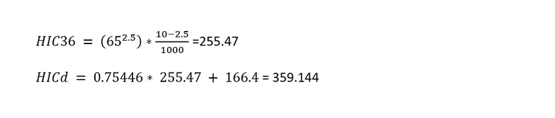
The following table summarises the calculation of HIC values using the above equations for three different simulated scenarios.
|
Case |
HIC 36 |
HIC d |
|
Impact of the simple head with rigid wall |
6.819 E+08 |
5.1446 E+08 |
|
Impact of head form with rigid wall |
3.0065 E+04 |
2.2849 E+04 |
|
Impact of head form with hood model |
255.4 |
359.144 |
5 Conclusion
The main aim of the Week 7 challenge was to create an input deck or setup file to perform the impact test of pedestrian head form with the hood model using LS-DYNA software. In addition, plot stress/ strain contours for the three different impact scenarios and calculate HIC values for the same. After evaluating the plots, it was found that the impact of the simple head with the rigid wall has the highest HIC value (6.819 E+08) meaning severe injuries to the pedestrian while the impact of head form with the hood model has the least value of HIC (255.4) resulting in minimal or mild injuries to the pedestrian. Moreover, the HIC values calculated using LS Pre-Post and manually were approximately similar.