Assignment 1-2D Meshing Challenge
Project 1 Challenge: 2D Meshing Challenge
Course: Crashworthiness Analysis using HyperMesh and Radioss
Submitted by: Amanpreet Singh Whan
Supervisor: Harsha Chowdary
December 02, 2021
List of Figures
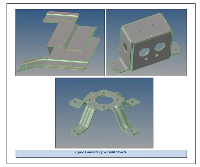
Figure 1-Imported given CAD Models.
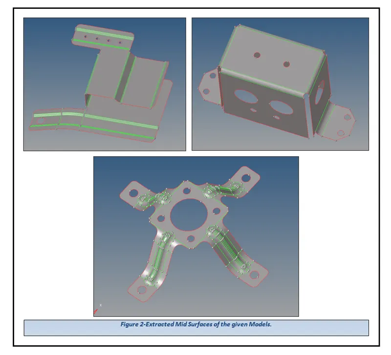
Figure 2-Extracted Mid Surfaces of the given Models.
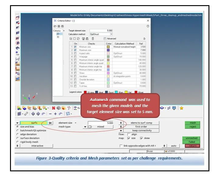
Figure 3-Quality criteria and Mesh parameters set as per challenge requirements.
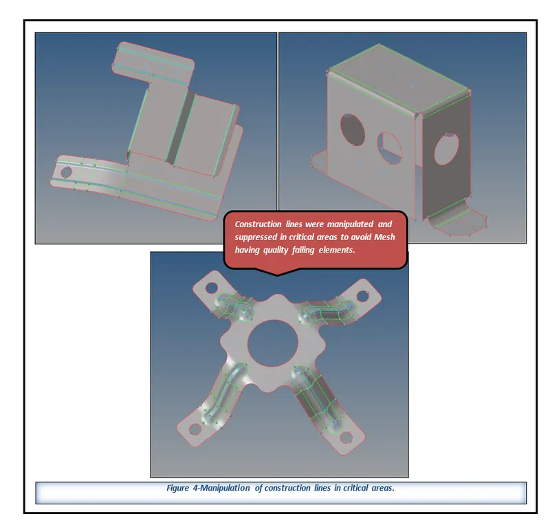
Figure 4-Manipulation of construction lines in critical areas.
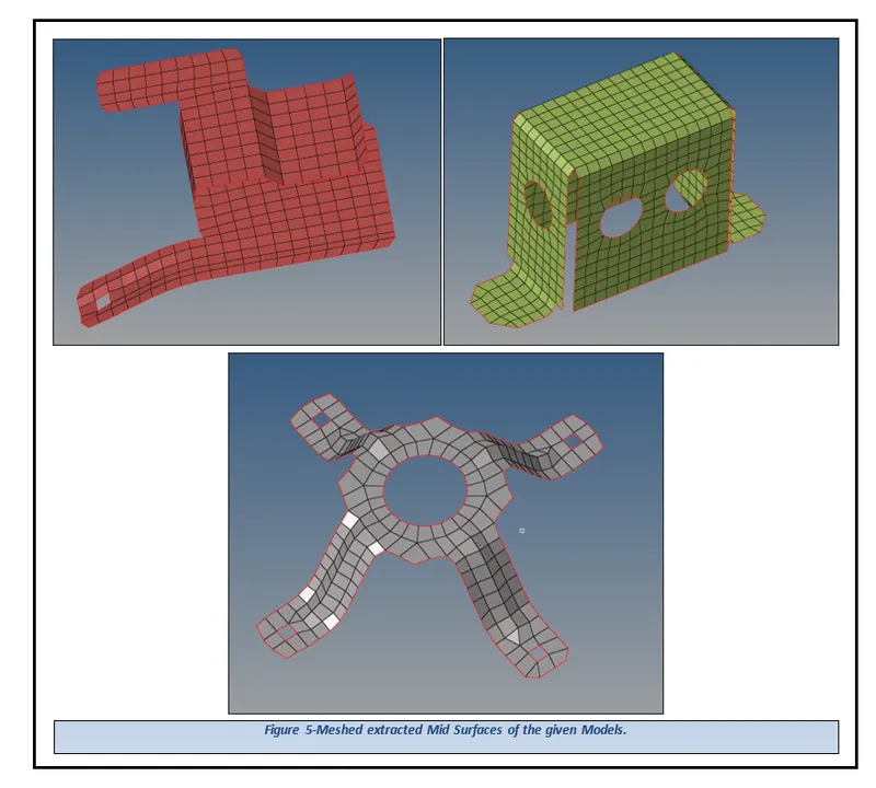
Figure 5-Meshed extracted Mid Surfaces of the given Models.
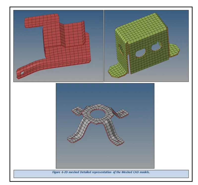
Figure 6-2D meshed Detailed representation of the Meshed CAD models.
Table of Contents
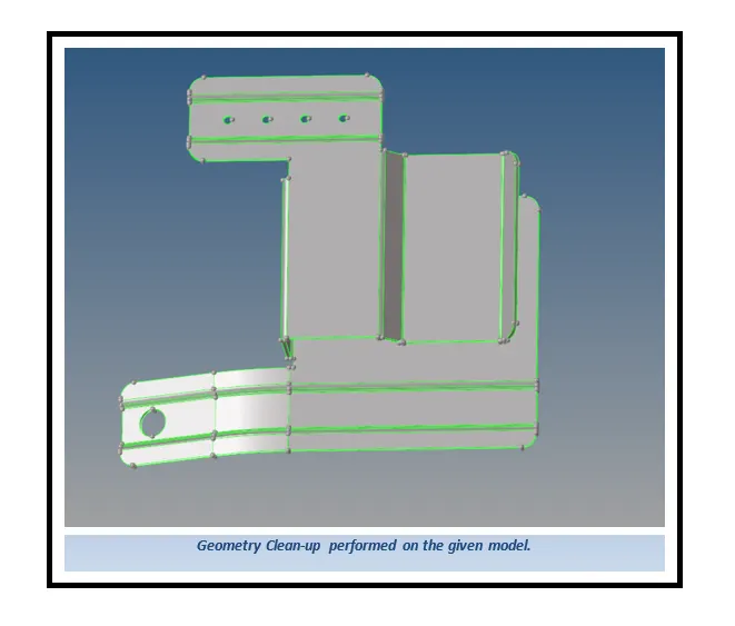
3.1 Geometry Clean-up of the given CAD Model
3.2 Extracting Mid Surface of the given Models.
3.3 Shell Meshing of Extracted Mid Surfaces of the Door Inner Panel Model
1 Introduction
HyperMesh is the market-leading, multi-disciplinary finite element pre-processor which manages the generation of the largest, most complex models, starting with the import of CAD geometry to exporting a ready-to-run solver file. HyperMesh supports a wide variety of CAD and solver interfaces, making it a perfect solution for most industry verticals and domains. With its advanced geometry and meshing capabilities, HyperMesh provides an environment for rapid model generation. Generating high-quality mesh quickly is just one of Hyper Mesh’s core competencies. For complex sub-system generation and assembly, HyperMesh has advanced model assembly tools. Modeling of laminate composites is supported by advanced creation, editing, and visualization tools. Design changes can be made easily via mesh morphing and geometry dimensioning.
2 Aims
- Check and fix all the geometrical errors of the given Models for Geometry Clean-up purposes.
- Extract/ Generate Middle Surfaces for the given models.
- Perform 2D or Shell Meshing of the extracted mid surfaces as per the given Mesh Quality Criterion to generate an overall good mesh flow for the entire model.
- Investigate and Improve the mesh quality wherever required.
3 Methodology and Results
The section describes the different stages that were performed using an engineering tool HyperWorks 2020 for the completion of the Project 1 Challenge task. These stages can be further broadly sub-categorized into three key steps, starting from importing of cad model to geometry clean-up for mid surface generation and finally carrying out meshing of the extracted mid surfaces as per quality requirements.
3.1 Geometry Clean-up of the given CAD Model
After opening the HyperWorks software, the first and foremost step is to import the given CAD models and then patch up any free edges highlighted in red lines or cons for geometric clean-up purposes.
3.2 Extracting Mid Surface of the given Models
The mid surface of a CAD design can be generated both manually and automatically. To generate mid surface automatically, click on the Mid surface tool under Geometry Module buttons and use the Auto Midsurface-> Skin offset command to extract mid surface for the given CAD models.
The results of the mid surfaces obtained using the Offset-> Surface command for the different features of the given CAD model are presented in the following pictures.
3.3 Shell Meshing of the Extracted Mid Surfaces
Meshing is a phase where the CAD geometry is discretized to represent the computational domain in which the solver will discover a solution. A refined mesh helps to achieve better results. Before proceeding with meshing, it is important to create a washer split across circular regions and can be deployed using the washer split command from quick edit options under Geometry Module buttons.
The Automesh command was used to mesh the given CAD models. The adopted meshing technique and obtained results are presented in the following pictures.
The meshing conducted for the given model is explained in the following steps:
- The target element size was set to 5 mm for the given CAD model. This will help to generate a mesh of constant element size.
- In the next step, the values of Quality Criteria and Mesh Parameters were entered as per challenge requirements to get a good flow of the mesh over the model. The values used for the quality criteria and mesh parameters are presented in the following tables.
|
Quality Criteria |
|
|
Criteria |
Value |
|
Target size |
5 |
|
Min length |
3.5 |
|
Max length |
7 |
- ‘Automesh’ command was used to produce 2D mesh for the model.
The results of the meshed CAD Models are presented in the following pictures.
4 Conclusion
In conclusion, the main aims of the Project 1 Challenge were to perform geometry clean-up, extract the middle surface for the given CAD models and finally perform shell meshing as per given quality requirements.
5 Appendix