Week 4
Week 4 Challenge: Shell (2D) Meshing of Bottle Cap Model using ANSA Preprocessor tool
Course: Preprocessor for Structural Analysis using ANSA
Submitted by: Amanpreet Singh Whan
Supervisor: David Nirmal Paul
November 4, 2020
Abstract
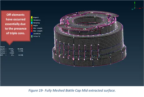
A bottle cap simply acts as a seal for the top opening of the bottle and made of either a metal or plastic material. The report presents a strategy that was adopted to mesh the given Bottle Cap using the ANSA Pre-Processor tool for the fulfilment of the Week 4 challenge task. The shell meshing is a three-step process that includes geometry clean-up, mid surface extraction and finally performing meshing using setting quality and mesh parameters. The max quads percentage and max trais percentage were found to be 98.85% and 1.15 % respectively. A total of 61 (0.54%) Off elements were also found in the regions where triple cons either intersect each other or are present very close to construction lines.
Table of Contents
3.1 Import CAD Model and do Geometry Clean-Up
List of figures
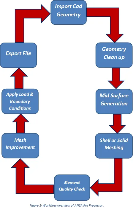
Figure 1-Workflow overview of ANSA Pre Processor.
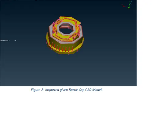
Figure 2- Imported given Bottle Cap CAD Model.
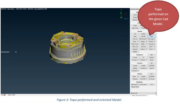
Figure 3- Topo performed and oriented Model.
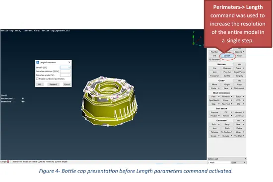
Figure 4- Bottle cap presentation before Length parameters command activated.
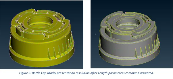
Figure 5- Bottle Cap Model presentation resolution after Length parameters command activated.
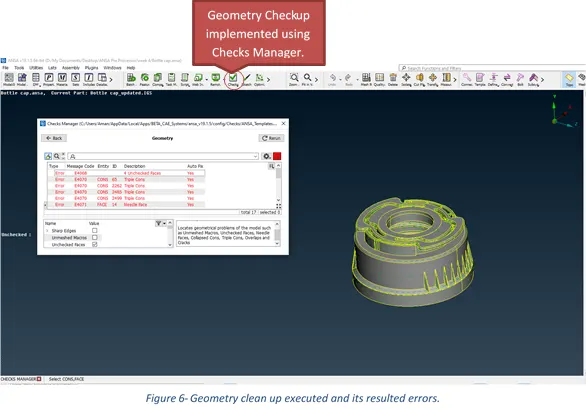
Figure 6- Geometry clean up executed and its resulted errors.
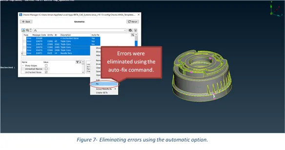
Figure 7- Eliminating errors using the automatic option.
Figure 8-Error free Bottle Cap CAD Model.
Figure 9- Mid Surfaces extracted for Outer Ribs.
Figure 10- Mid surfaces extracted for Inner Ribs.
Figure 11- Mid surfaces extracted for threads.
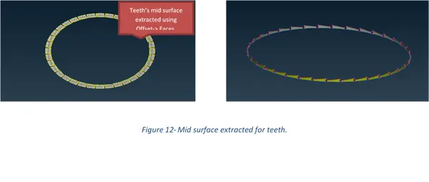
Figure 12- Mid surface extracted for teeth.
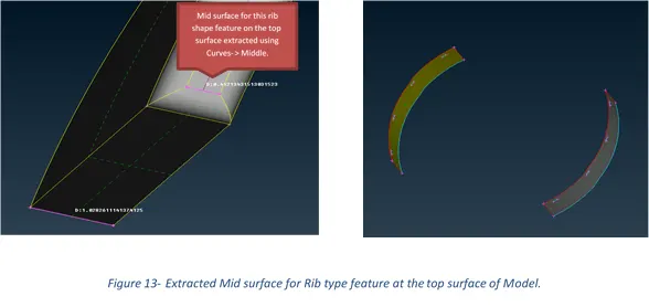
Figure 13- Extracted Mid surface for Rib type feature at the top surface of Model.
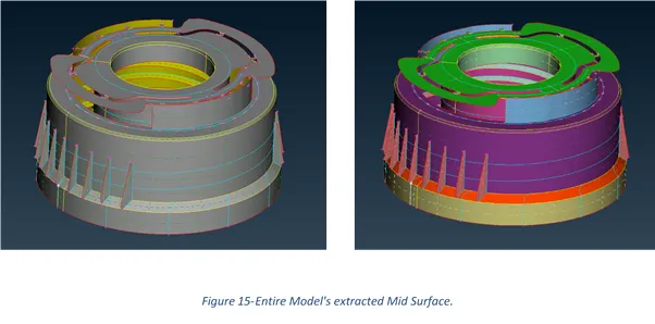
Figure 15-Entire Model's extracted Mid Surface.
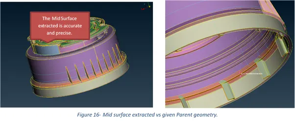
Figure 16- Mid surface extracted vs given Parent geometry.
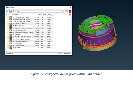
Figure 17- Assigned PIDs to given Bottle Cap Model.
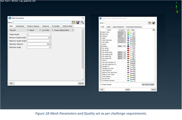
Figure 18-Mesh Parameters and Quality set as per challenge requirements.
Figure 19- Fully Meshed Bottle Cap Mid extracted surface.
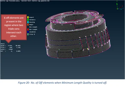
Figure 20- No. of Off elements when Minimum Length Quality is turned off.
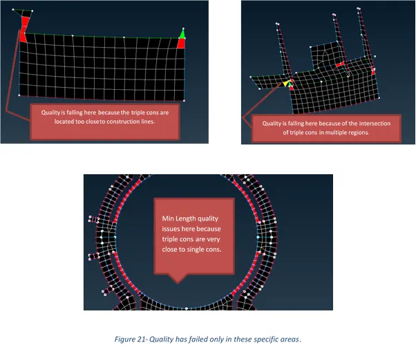
Figure 21- Quality has failed only in these specific areas.
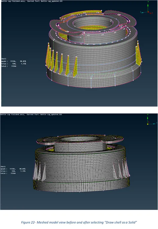
Figure 22- Meshed model view before and after selecting "Draw shell as a Solid".
1 Introduction
A bottle cap helps to seal the top opening of a bottle. In the past, the bottle caps used for carbonated beverages were usually made of metals such as aluminium and steel. These caps were either crimped to the neck of the bottle or threaded onto the bottleneck. Nowadays, the industries have however decided to use plastic caps constructed either for a snap-fit onto the bottleneck or threaded engagement with cooperating threads on the bottleneck. Plastic caps having threaded engagement can be used for both glass bottles and plastic bottles.
2 Aims
- Check and fix all the geometry errors of the given Model for Geometry Clean-up purposes.
- Extract/ Generate Middle Surface for all the components of the given model.
- Perform 2D or Shell Meshing of the components of the model as per given Mesh Quality Criterion to generate an overall good mesh flow for the entire model.
- Investigate and Improve the mesh quality wherever required.
3 Methodology and Results
The section describes the different stages that were performed using an engineering tool, ANSA Pre-Processor for the successful generation of an overall good mesh for the completion of the Week 4 Plastic Bottle Cap project. These stages can be further broadly sub-categorised into three key steps, starting from importing of cad model to geometry clean-up for mid surface generation and finally carry out meshing of the extracted mid surface as per quality requirements.
ANSA Pre Processor is an advanced computer-aided engineering tool extensively used for FEA (Finite Element Analysis) and CFD (Computational Fluid Dynamics) analysis in the automotive and aerospace industry. ANSA pre-processor is a CAE software developed by BETA CAE Systems and follows a strict workflow when numerically solving a given problem. Figure 1 represents the workflow overview implemented in the software.
3.1 Import CAD Model and do Geometry Clean-Up
After opening the ANSA Pre-processor software, the first and the foremost step is to import the CAD geometry and perform topology using the topo command in the faces section of Topo Module Buttons for the entire model.
Since the given model is a plastic component and does not have a uniform thickness, so, its refinement was necessary for presentation resolution before proceeding with the extraction of the middle surface. The model can be refined either using Auxilaries-> fine in Topo Module Buttons or by simply setting a value of length for the entire model in the Perimeters section of Mesh Module Buttons. Considering the complexity of the fine operation, Mesh perimeters-> Length was chosen to be the easiest and preferable choice.
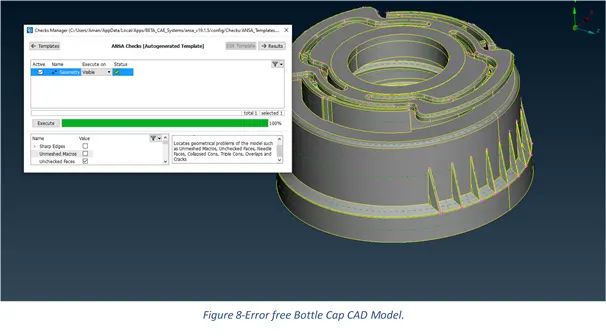
In the next step, go to the Checks Manager and select geometry from the options list. The main function of the Checks geometry is to locate geometrical issues such as unmeshed macros, unchecked faces, needle faces, collapsed cons, triple cons, and cracks. Even though most of these errors can be easily eliminated using the Auto-Fix command but issues concerning triple cons must be fixed manually by releasing Cons or Hot-points (nodes) and joining cons/ nodes back again using the topo command. Before executing the Checks geometry operation, make sure to turn on the most essential above stated geometry issues.
What follows hereafter is the set of images showing different results obtained before and after the completion of geometry clean-up using ANSA Pre-Processor software.
3.2 Mid Surface Extraction
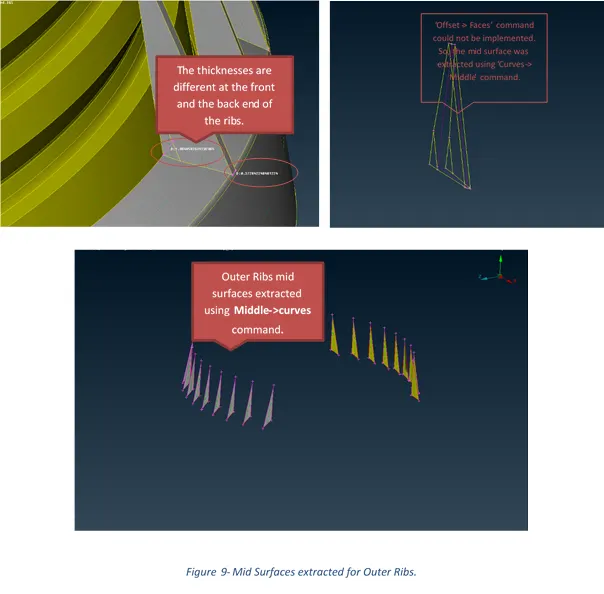
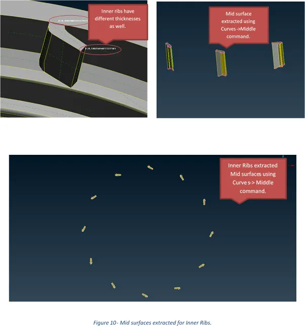
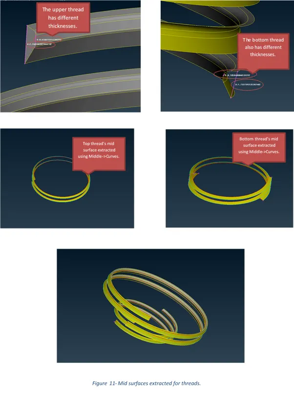
The mid surface can be generated both manually and automatically. A manual mid surface can be obtained using the Faces->Offset command in the Faces section of Topo module buttons. Moreover, the mid-surface generated using manual operation must be assigned a new PID which can be easily done using the Set PID command in the faces section. However, ANSA directly assigns a new PID to a Mid Surface that is extracted automatically, and it is usually accomplished using Mid Surface->Skin command in the faces section.
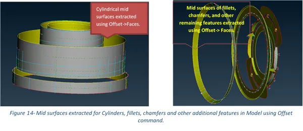
The results of the mid surfaces obtained manually (using the commands, Faces->offset and Curves-> Middle) for the different regions of the given CAD model are presented in the following pictures.
3.3 Meshing
Meshing is a phase where the CAD geometry is discretised to represent the computational domain in which the solver will discover a solution. A refined mesh helps to achieve better results.
The meshing conducted for the given model is explained in the following steps:
- After the extraction of mid surfaces, the Perimeters length was set to 1 mm in the perimeters section of the Mesh module buttons. This will help to generate a mesh of constant element size.
- In the next step, the values of Quality Criteria and Mesh Parameters were entered as per challenge requirements to get a good flow of the mesh over the model. The values used for the quality criteria and mesh parameters are presented in the following tables.
Table 1-Quality criteria and its respective assigned values
|
Quality Criteria |
|
|
Criteria |
Value |
|
Aspect Ratio |
3 |
|
Skewness |
45 |
|
Warping |
15 |
|
Jacobian |
0.7 |
|
Min length |
0.5 |
|
Max length |
3 |
|
Min angle quads |
45 |
|
Max angle quads |
135 |
|
Min angle trias |
30 |
|
Max angle trias |
120 |
|
Tria Percentage |
15 |
Table 2- Mesh Parameters and its assigned values
|
Mesh Parameters |
|
|
Parameters |
Value |
|
Target length |
1 |
|
Minimum target length |
0.5 |
|
Maximum target length |
3 |
|
Distortion distance |
15% |
|
Distortion angle |
0 |
- A combination of the ‘Best’ and ‘Spot Mesh’ Mesh Generation algorithms was used to produce mesh for the model.
- Quality failing elements were eliminated using multiple approaches which include Reconstruction of mesh, smoothing of mesh, Moving & Pasting Grids, and Splitting, Swapping & Joining of elements.
The results of the meshed model are presented in the following pictures.
4 Discussion
ANSA Pre-Processor was used to mesh the Bottle Cap CAD model as per asked Quality Criteria and Mesh Parameters to generate a good overall mesh flow for the successful completion of the Week 4 Challenge. To fulfil the requirements of the challenge, Geometry clean-up along with Mid Surface extraction and Meshing was performed and the obtained results are presented in the figures shown above.
In figure 7, the provided CAD model had multiple errors such as needle faces, cracks, unchecked faces and triple cons which were fixed using the automated fix option.
Since the given bottle cap model is a plastic component and has non-uniform thickness throughout, the mid extraction was not possible by simply using the Offset-> Faces command. Therefore, Curves-> Middle command was used to extract mid surfaces in the regions of varying thicknesses. In figures 9-12, the specific regions are designated where this command has been applied to extract the mid surface.
In PID mode, by selecting the extracted mid surface and the parent component while keeping the parent component in transparency mode and it was found that the mid extracted falls exactly in the middle of the parent component of geometry, concluding mid extraction performed was accurate and precise.
Figure 20 instructs a total of 61 off or quality failed elements are present in the meshed model. 55 elements have failed for minimum length quality while the rest six have failed for both skewness and aspect ratio. In figure21, the quality has failed in the locations where triple cons intersected each other or are present very close to the construction lines. However, these errors cannot be eliminated and can be neglected.
5 Conclusion
In conclusion, the main aim of the challenge was to do a geometry clean-up of the Bottle Cap model, generate its mid surface and perform 2D meshing. The max quads percentage was found to be 98.85% while the max trias percentage was found to be 1.15%. Moreover, 61 quality failed elements were found in the areas either where triple cons are very close to construction lines or in the areas where triple cons intersect each other. Lastly, the meshed model was assigned a thickness by enabling the ‘Draw shell as a solid’ command in the Quality Criteria- Presentation Parameters tab.
6 Learning Outcomes
Throughout this challenge, I have gained knowledge about different commands that are used to fix geometry errors and are used to generate the mid surface of any CAD Model with both auto and manual options. I have also learned that the Mesh Quality can be fixed using several operations like ‘mesh reconstruction’, ‘mesh smoothing,’ ‘grids move or paste’, and ‘elements split and join’.
Appendix