Week 3 Sheet metal Bending challenge
Week 3 Challenge: Sheet Metal Bending Challenge
Course: Structural Analysis Using Ansys Workbench
Submitted by: Amanpreet Singh Whan
Supervisor: Vineet G
March 05, 2022
List of Figures
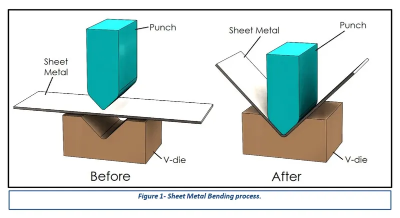
Figure 1- Sheet Metal Bending process.
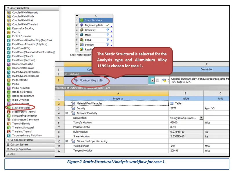
Figure 2-Static Structural Analysis workflow for case 1.
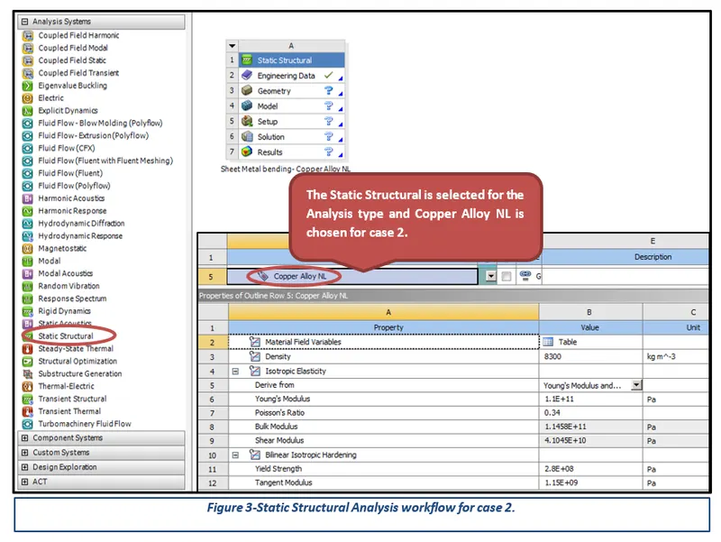
Figure 3-Static Structural Analysis workflow for case 2.
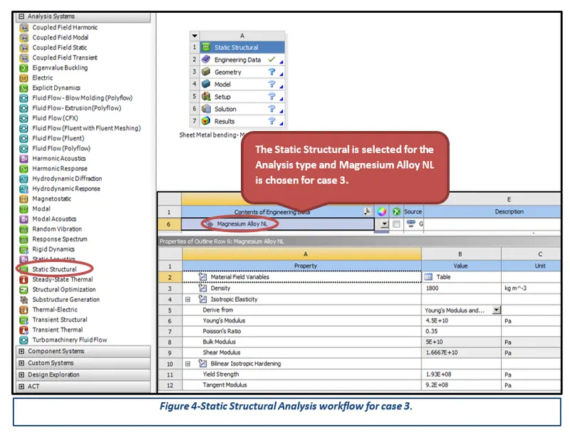
Figure 4-Static Structural Analysis workflow for case 3.
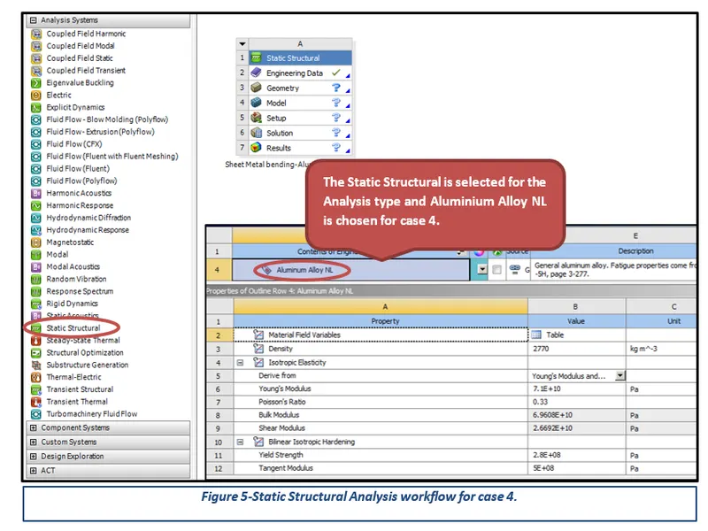
Figure 5-Static Structural Analysis workflow for case 4.
Figure 6-Imported given CAD Model.
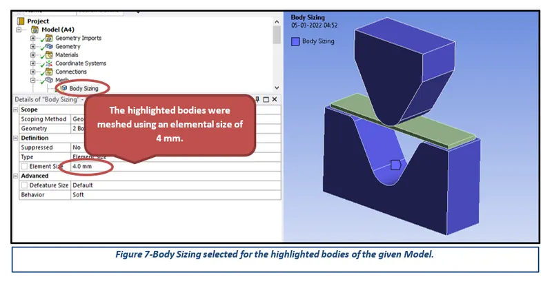
Figure 7-Body Sizing selected for the highlighted bodies of the given Model.
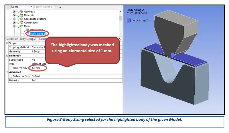
Figure 8-Body Sizing selected for the highlighted body of the given Model.
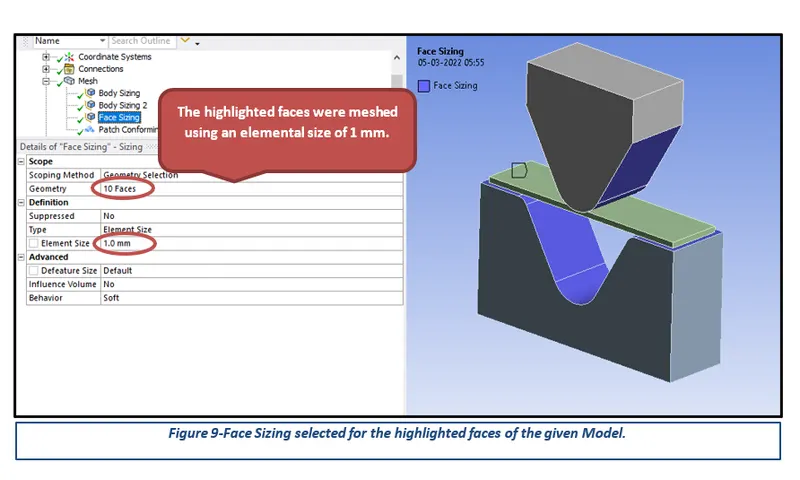
Figure 9-Face Sizing selected for the highlighted faces of the given Model.
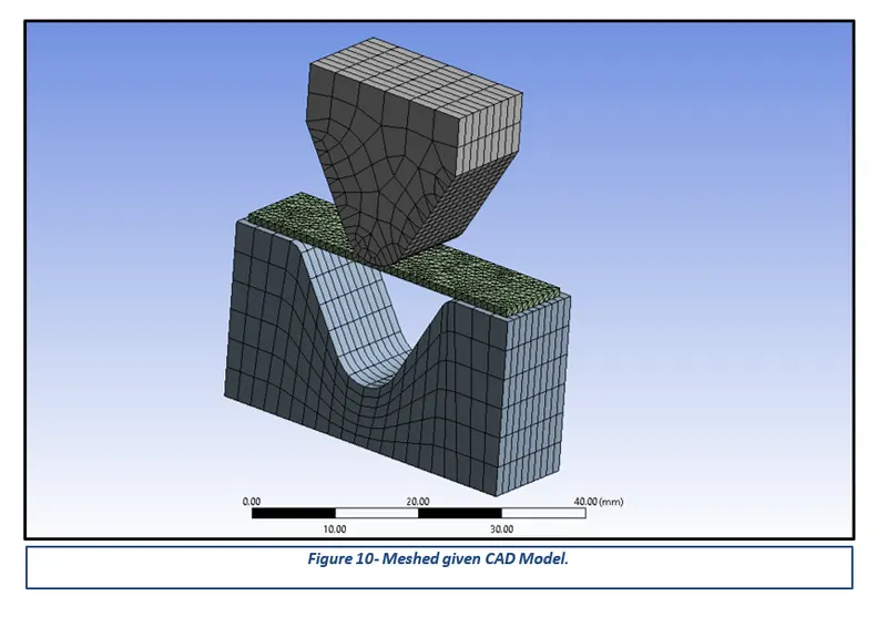
Figure 10- Meshed given CAD Model.
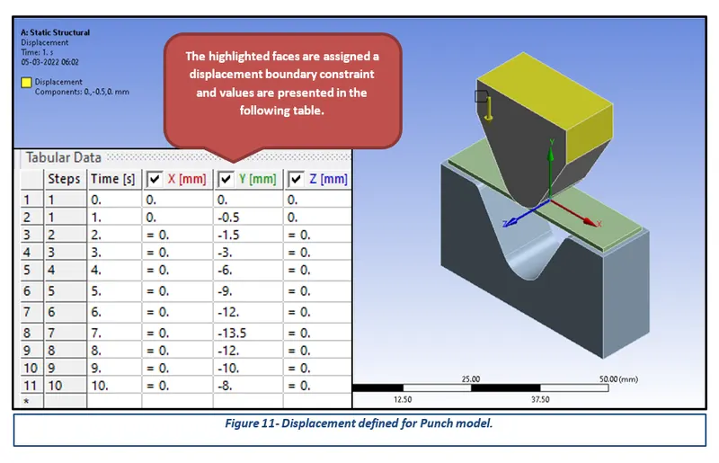
Figure 11- Displacement defined for Punch model.
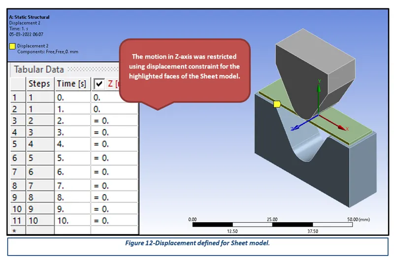
Figure 12-Displacement defined for Sheet model.
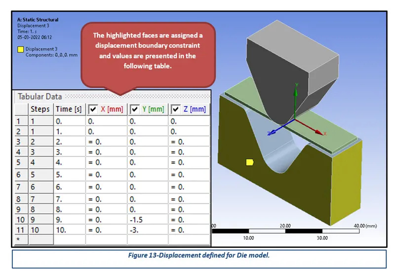
Figure 13-Displacement defined for Die model.
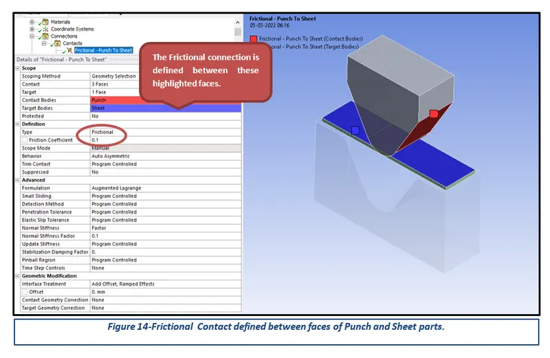
Figure 14-Frictional Contact defined between faces of Punch and Sheet parts.
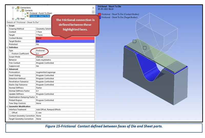
Figure 15-Frictional Contact defined between faces of Die and Sheet parts.
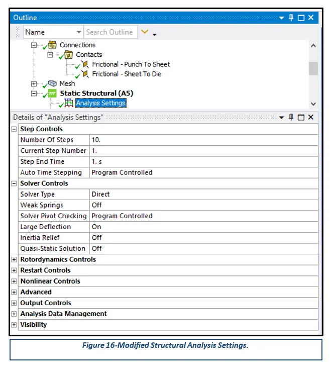
Figure 16-Modified Structural Analysis Settings.
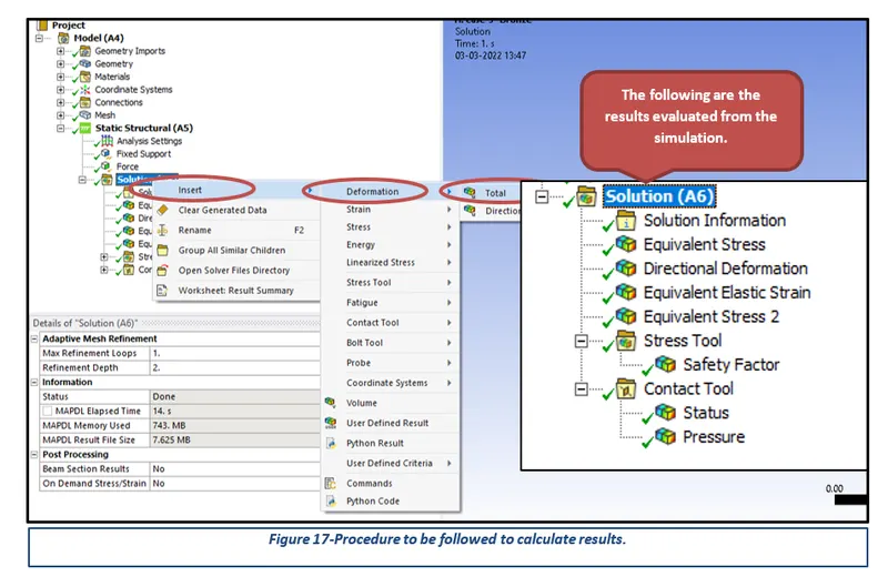
Figure 17-Procedure to be followed to calculate results.
Table of Contents
3.1 Importing and Meshing of CAD Model
1 Introduction
ANSYS is a general-purpose, finite-element modelling package for numerically solving a wide variety of mechanical problems. These problems include static/dynamic, structural analysis, heat transfer, and fluid problems, as well as acoustic and electromagnetic problems. There are two methods to use ANSYS. One method is to use the graphical user interface (GUI). This method follows the conventions of popular Windows and X-Windows-based programs. Another method is to use command files. The command-file approach has a steeper learning curve for many, but it has the advantage that the entire analysis can be described in a small text file, typically in less than 50 lines of commands. This approach enables easy model modifications and minimal file-space requirements. The ANSYS environment contains the main window and an output window. A large number of files are created when ANSYS simulation is run.
Theory
The bending of sheet metal is a common and vital process in the manufacturing industry. Sheet metal bending is the plastic deformation of the work over an axis, creating a change in the part's geometry. Similar to other metal forming processes, bending changes the shape of the workpiece, while the volume of material will remain the same. In some cases, bending may produce a small change in sheet thickness. For most operations, however, bending will produce essentially no change in the thickness of the sheet metal. In addition to creating a desired geometric form, bending is also used to impart strength and stiffness to sheet metal, to change a part's moment of inertia, for the cosmetic appearance and to eliminate sharp edges.
Metal bending enacts both tension and compression within the material. Mechanical principles of metals, particularly elastic and plastic deformation, are important to understanding sheet metal bending and are discussed in the fundamentals of metal forming section. The effect that material properties will have in response to the conditions of manufacture will be a factor in sheet metal process design. Usually, sheet metal bending is performed cold but sometimes the work may be heated, to either warm or hot working temperature.
Most sheet metal bending operations involve a punch die type setup, although not always. There are many different punches die geometries, setups and fixtures. Tooling can be specific to a bending process and a desired angle of bend. Bending die materials are typically Gray iron or carbon steel, but depending on the workpiece, the range of punch-die materials varies from hardwood to carbides. A press will usually provide force for the punch and die action. A workpiece may undergo several metal bending processes. Sometimes it will take a series of different punch and die operations to create a single bend. Or many progressive bending operations to form a certain geometry.
Sheet metal is referenced about the workpiece when bending processes are discussed in this section. However, many of the processes covered can also be applied to plate metal as well. References to sheet metal workpieces may often include plates. Some bending operations are specifically designed for the bending of differently shaped metal pieces, such as for cabinet handles. Tube and rod bending is also widely performed in modern manufacturing.
2 Aims
- Simulate Sheet Metal Bending using three different materials for the given Model.
- Change Frictional coefficient from 0.1 to 0.19 and compare results for the Alloy Material.
- Refine the Mesh Size and compare the directional deformation results.
- Apply appropriate Boundary Conditions and Joint Loads.
- Lastly, Determine Total Deformation and Maximum Stress results for the performed simulations and compare the results for the same.
3 Methodology and Results
The section describes the different stages that were performed using an engineering tool Ansys Workbench 2022 for the completion of the Week 3 Challenge. These stages can be further broadly sub-categorised into three key steps, importing the CAD model to apply the boundary conditions and finally performing the simulation to obtain the desired results.
3.1 Importing and Meshing of CAD Model
After opening the Ansys Workbench, the first step is to select the Analysis type and then define appropriate material from the Engineering Data options for the given CAD model. Considering the challenge requirements, Static Structural was selected for the System Analysis type while three different materials such as Aluminium Alloy 1199, Copper Alloy NL and Magnesium Aloy NL were selected for the challenge purposes. The following figures highlight the analysis system and material card parameters in detail.
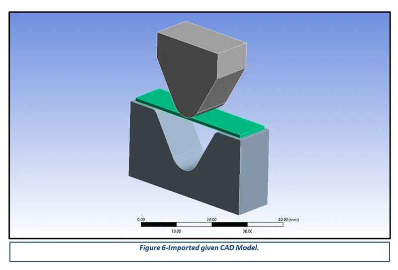
After updating the CAD model in the Ansys Workbench, the next step is to generate a good quality mesh. Meshing is a phase where the CAD geometry is discretised to represent the computational domain in which the solver will discover a solution. A refined mesh helps to achieve better results. The mesh was generated in three steps: the body sizing method with an element size of 4 mm and 1 mm were used to refine the faces in contact; for other areas in contact the mesh was generated using an element size of 1 mm.
3.2 Boundary Constraints
Boundary conditions are constraints necessary for the solution of a boundary value problem. The Fixed support constraint restricts all the translation degrees of freedom over the assigned entities to be zero. The force boundary condition applies a distributed force to the structure. It can be assigned to any number of faces of a structure. This boundary condition works as surface traction on each element of the assigned topological entity and its value is proportional to each element’s area.
Three Displacements constraints are assigned to fulfil the challenge requirements. The process followed to assign the boundary constraints is presented in the following figures.
3.3 Contact
In structural analysis software, the contact is generated by pair. Three different contact behaviours are available. They are named node to node (point to point), node to the surface (point to the surface) and surface to surface. As default in Ansys software, point to surface and surface to surface contact types are used. For the point to surface contact, the “point” is contact, and the “surface” is the target. Several contact types are used. These names might be called with different names according to software. In Ansys software, contact names are titled frictional, frictionless, rough, bonded and no separation. The Frictional Contacts were defined for the challenge purposes and is represented in the following figures.
3.4 Analysis Settings
The given spur gear model was simulated for a number of 10 steps in order to determine appropriate total deformation and other stress-strain results. Therefore, the Large Deflection option was turned on to prevent Penetration and Intersection errors. The following figure represents the modifications performed in the analysis settings.
Simulation Results
To visualise the simulation or results, the desired output cards have to be created. Total Deformation, Equivalent Elastic Strain and Equivalent Stress (Von Mises Stress) cards were created using the procedure illustrated in the following picture. It must be noted that the results have to be generated by running the solve command.
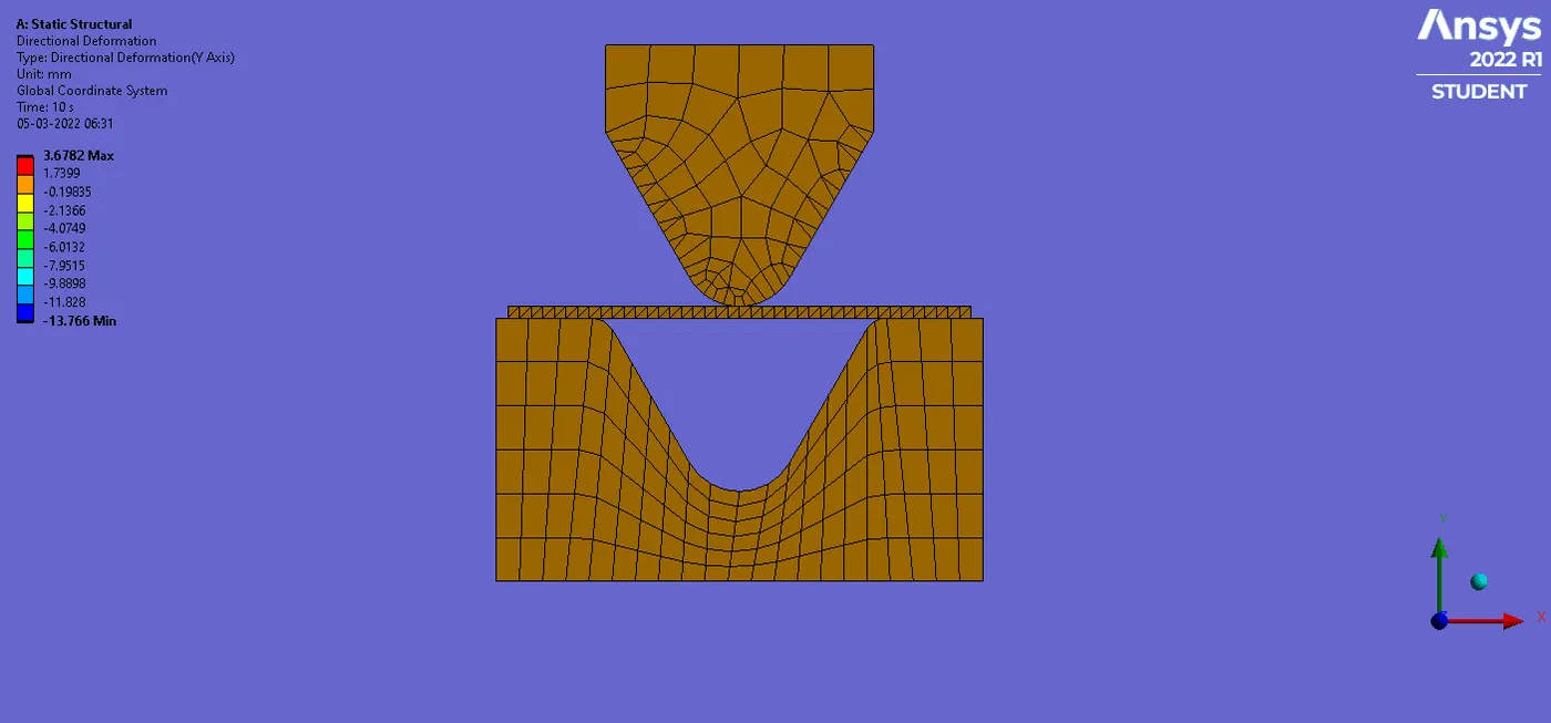
Case1: Simulation Results of Model having Aluminium Alloy 1199 Material
Deformation Results:
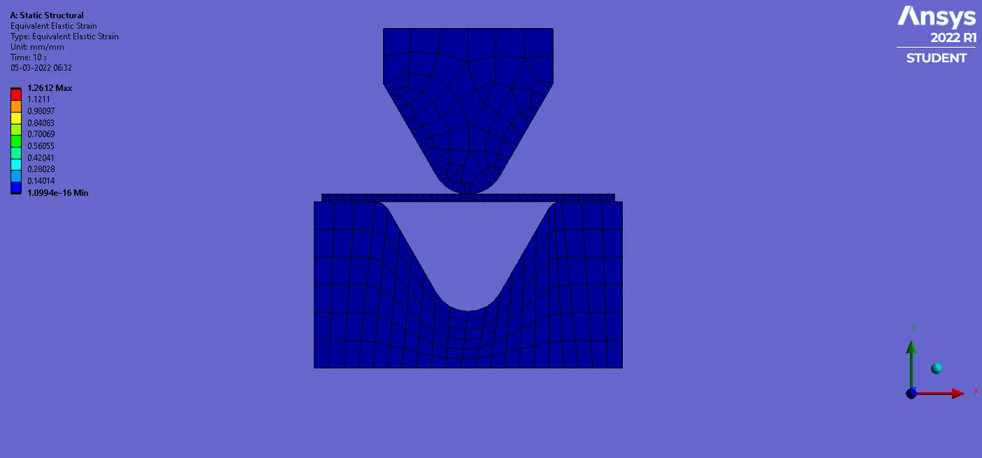
Strain Results:
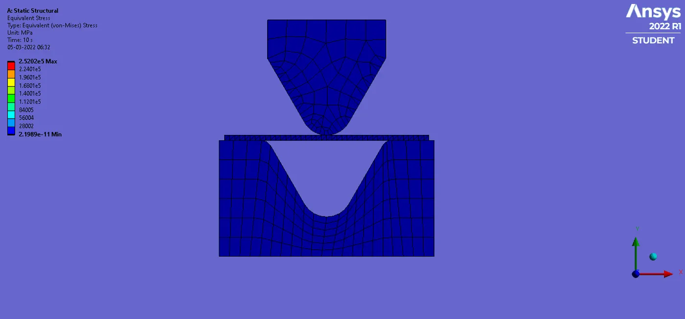
Stress Results:
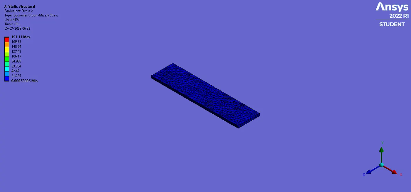
Case2: Simulation Results of Model having Copper Alloy NL Material
Deformation Results:
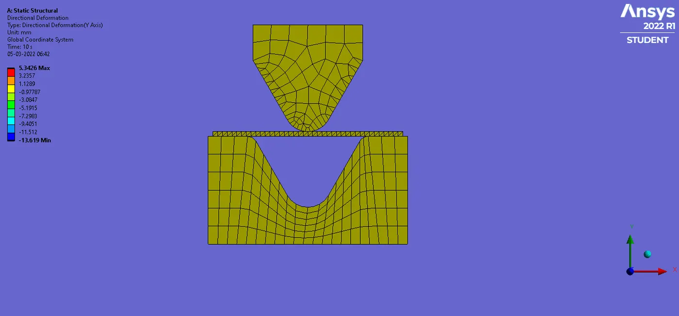
Strain Results:
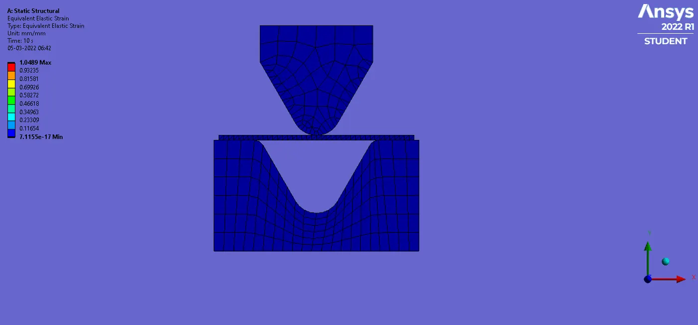
Stress Results:
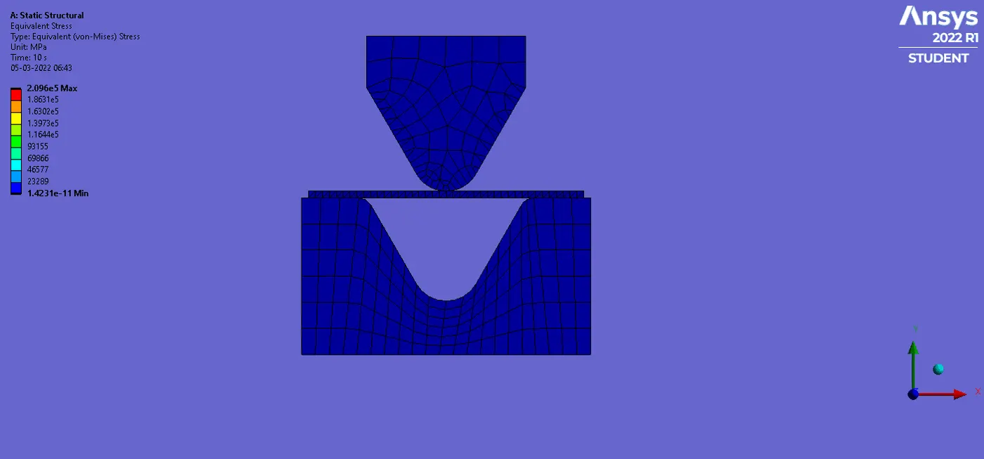
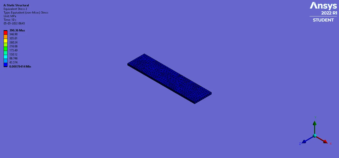
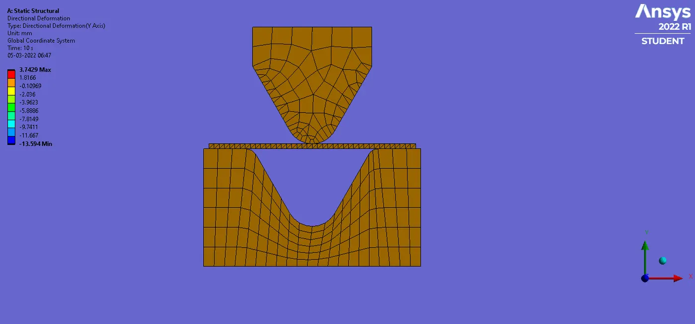
Case3: Simulation Results of Model having Magnesium Alloy NL Material
Deformation Results:
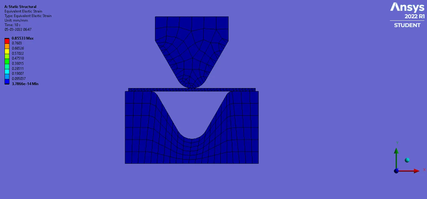
Strain Results:
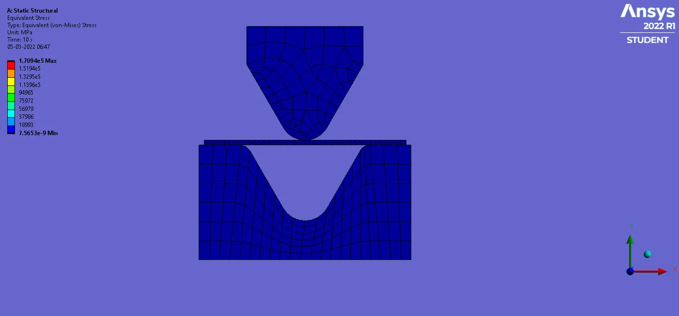
Stress Results:
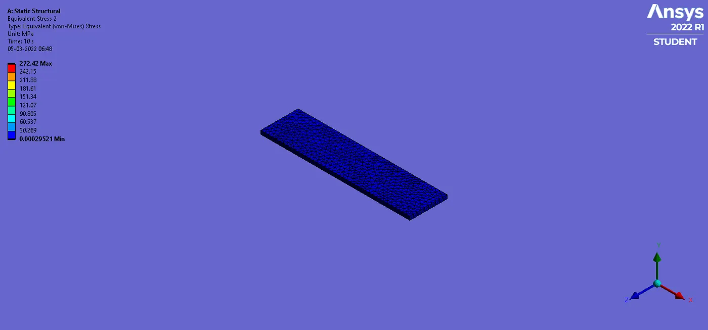
Case4: Simulation Results of Model having Aluminium Alloy NL Material
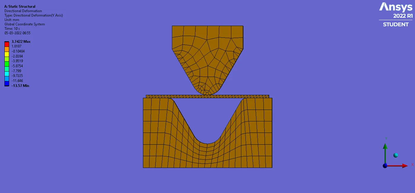
Deformation Results:
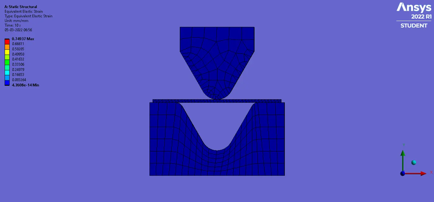
Strain Results:
Stress Results:
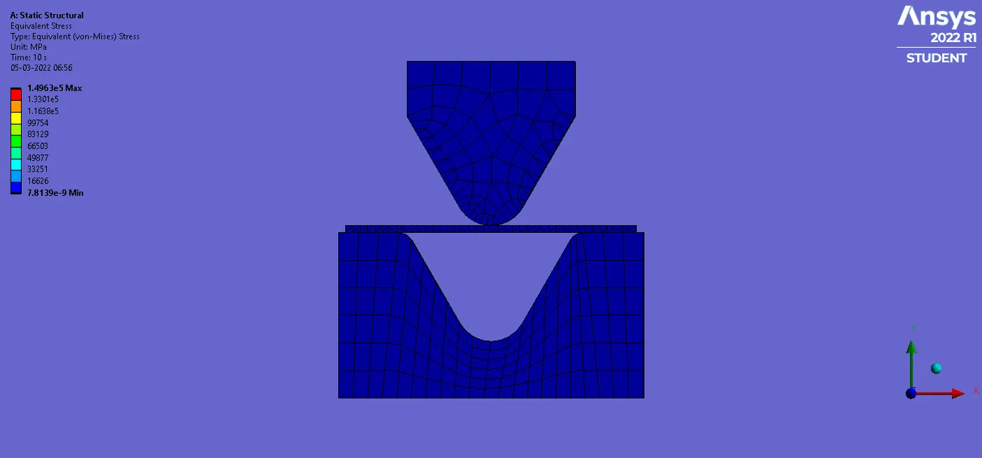
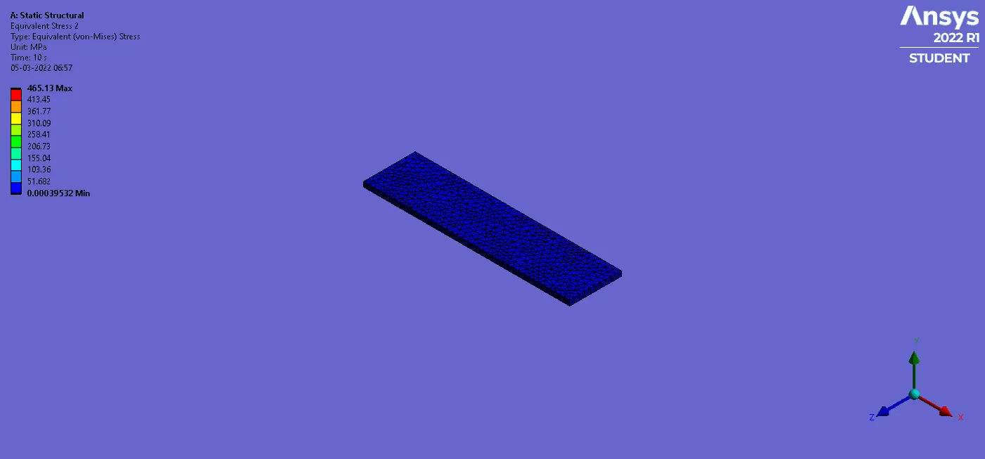
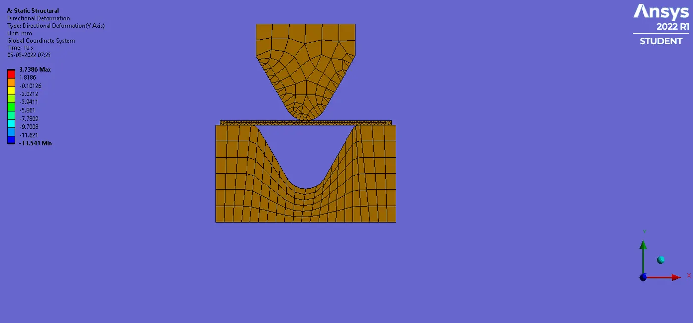
Case5: Simulation Results of Model having Aluminium Alloy NL Material and Refined Mesh for Plate
Deformation Results:
Strain Results:
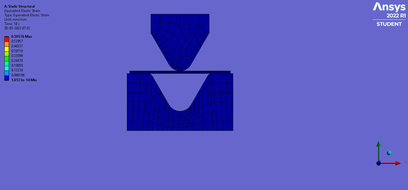
Stress Results:
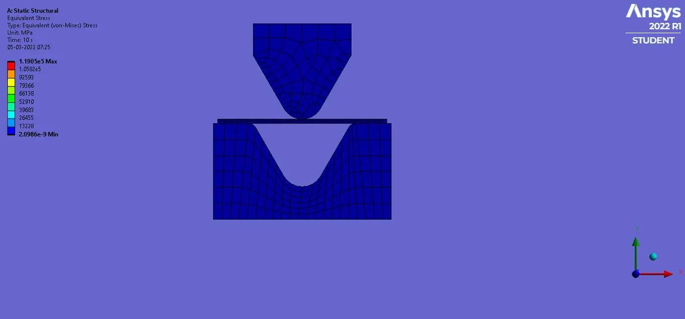
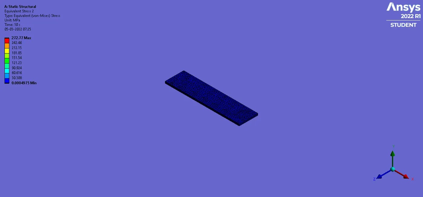
4 Conclusion
In conclusion, the main aim of the Week 3 challenge was to Simulate Sheet Metal Bending using three different materials for the given Model. In addition, perform the simulation for two more cases involving changing the frictional coefficient from 0.1 to 0.9 and refine the mesh for the plate model.
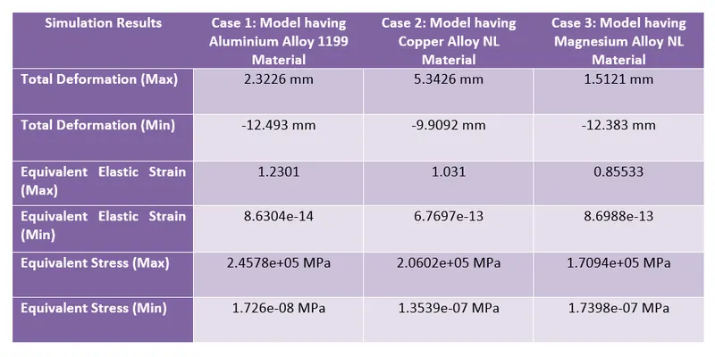
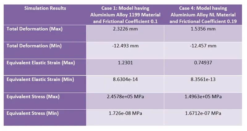
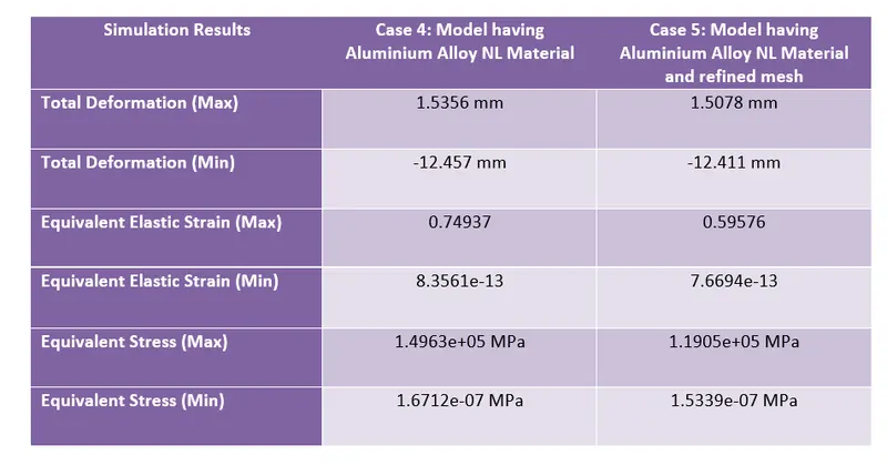
From the results, it was found that the total deformation resulted in case 3 having magnesium alloy NL material has minimum resulting directional deformation followed by case 1 having aluminium alloy 1199 and case 2 copper alloy NL material. The stress strains resulting in case 3 are minimum as well followed by case 2 and case 1.
It was also found that the directional deformation and stress-strain results generated in the models having aluminium alloy NL material with frictional coefficient 0.19 are smaller in comparison to models having aluminium alloy NL material with a frictional coefficient of 0.1. Lastly, the model having refined mesh for the plate model yields better stress-strain results.