Centrifugal pump design and analysis
Centrifugal pump design and analysis
Aim :
To design the centrifugal pump and analysis the performance of the centrifugal pump by using the flow simulation in solidworks software.
Objective :
- To create a 3D model of a centrifugal pump by using the part modelling tool.
- To simulate the water flow in the centrifugal pump by give the angular velocity to the impeller.
- To obtain the relationship between Pressure ratio and mass flow rate for various impeller speed.
Theory :
Centrifugal pumps are the most popular and commonly used type of pump for the transfer of fluids. In simple words, it is a pump that uses a rotating impeller to move or other fluids by using centrifugal force. These are the undisputed pump choice especially for delivering liquid from one location to another in numerous industries including agriculture, municipal (water and waste water plants), industrial, power generation plants, petroleum, mining, chemical, pharmaceutical and many others. Centrifugal pumps are useful since they can generally handle large quantities of fluids, provide very high flow rates (which may vary with the changes in the Total Dynamic Head (TDH) of the particular piping system) and have the ability to adjust their flow rates over a wide range. Centrifugal water or light oil. More viscous liquids such as 10 or 20 wt. oil at 68-70 deg F will require additional horsepower for centrifugal pumps to work. For viscous liquids of more than 30 wt. oil positive displacement pumps are preferred over centrifugal pumps to help lower energy costs.
Working of a Centrifugal Pump :
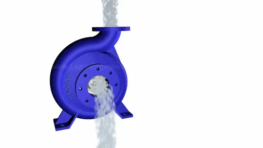
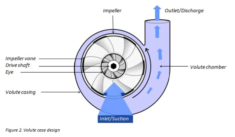
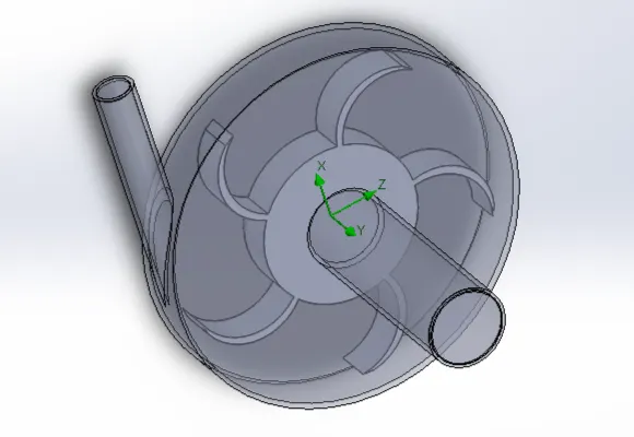
Let us understand in detail, how a Centrifugal pump works. Centrifugal pumps are used to include flow or raise a liquid from a low level to high level. These pumps work on a very simple mechanism. A centrifugal pump converts rotational energy, often from a motor, to energy in a moving fluid. The two main parts that are responsible for the conversion of energy are the impeller and the casing. The impeller is the rotating part of the pump and the casing is the airtight passage that surrounds the impeller. In a centrifugal pump, fluids enters into the casing, falls on the impeller blades at the eye of the impeller, and is whirled tangentially and radially outward untill it leaves the impeller into the diffuser part of the casing. While passing through the impeller, the fluid is gaining both velocity and pressure.
Application of Centrifugal Pumps :
The fact that centrifugal pumps are the most popular choice for fluid movement makes them a strong contender for many applications and as mentioned previously, they are used across numerous industries. Supplying water, boosting pressure, pumping water for domestic requirements, assisting fire protection system, hot water circulation, sewage drainage and regulating boiler water are among the most common applications. Outlined below are some of the major sectors that make use of these pumps.
- Oil & Energy - pumping crude oil,slurry,mud.
- Waste Management, Agriculture & Manufacturing - Wastewater processing plants, municipal industry, drainage, gas processing.
- Chemical & Food Industries - paints, hydrocarbons, petrochemical, cellulose, sugar refining.
Procedure :
Geometry Modelling of Pump :
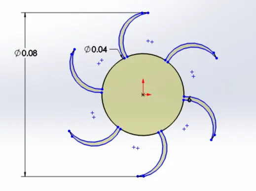
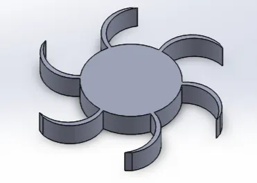
At first 3D model of the pump is made using part workbench. It comprises sketching of impeller, casing, inlet and outlet channels and a rotating extrusion for flow simulation.
Flow Simulation setup :
- After sketching, flow simulation was setup and lids were applied at two open face of inlet and outlet passages. From wizard inputs were given as,
- Analysis Type : Internal,
- Type of fluid : Water,
- Type of flow : Laminar and Turbulant,
- Wall conditions : Adiabatic with 0 micrometer roughness,
- Initial conditions : pressure (101325 Pa), Temperature (293.2K)
Input Data :
- Rotating Regions - select the impeller regions and give 1000 rpm.
- Boundary conditions :
- Inlet pressure - Environment pressure
- Outlet pressure - Environment pressure
- Goals :
- Inlet total pressure
- Outlet total pressure
- Mass flow rate
- Pressure Ratio
Results :
Velocity Trajectories :
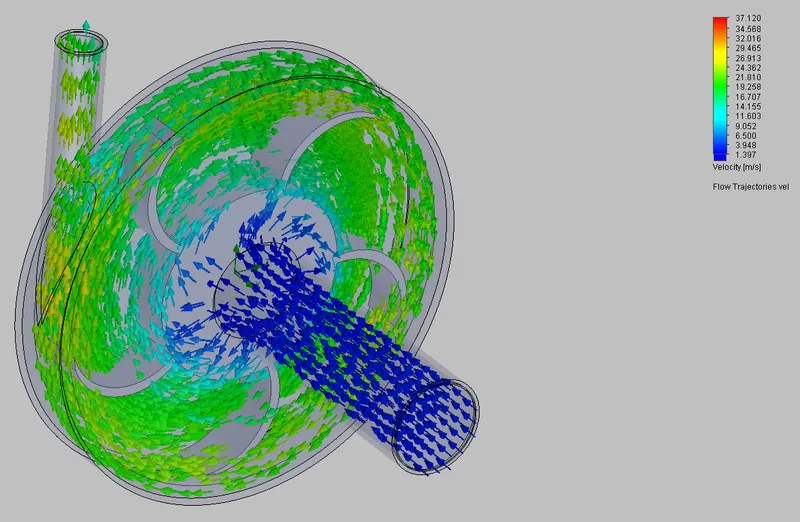
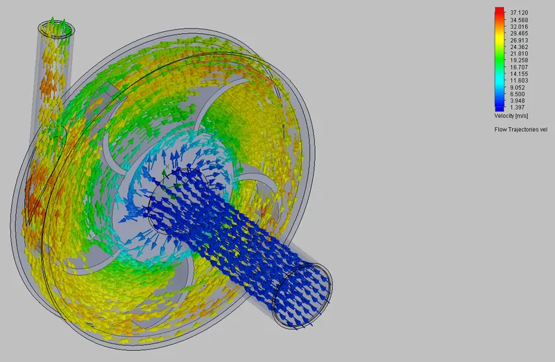
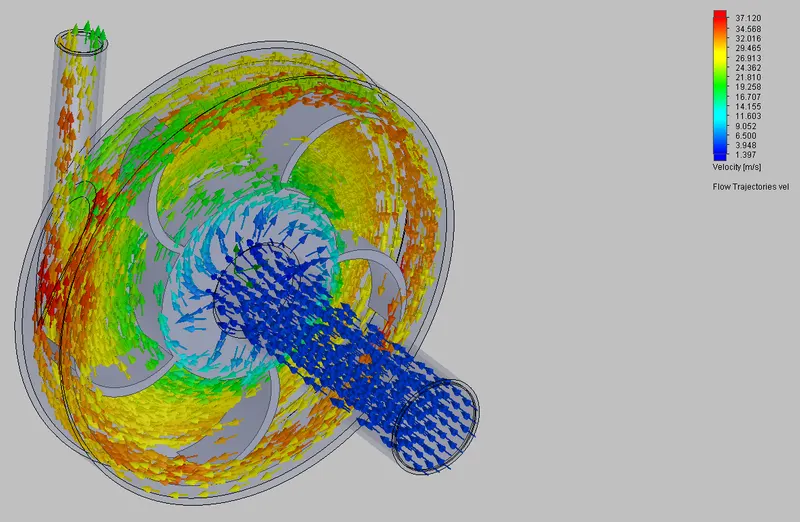
From the velocity trajectories low velocity (Blue color) in the inlet side and high velocity (Red color) in outlet side. As the impeller start rotating the centre of the impeller is low pressure created and it such the lnlet water into impeller. After some impeller rotation by the centrifugal force the velocity at the outer edge and it get outlet with high velocity. So, from the velocity trajectories we can say at the center of the impeller the velocity is low (5 m/s) and at the outer edge of the impeller velocity is high (34.2 m/s) and water get out from the outlet.
Pressure Trajectories :
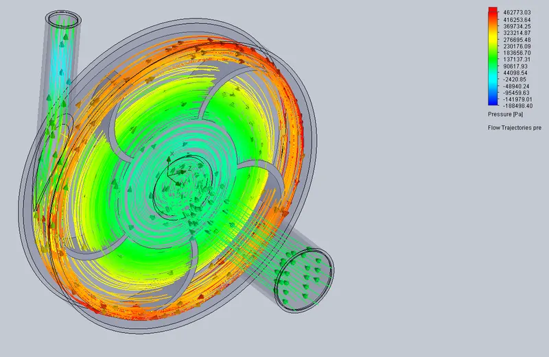
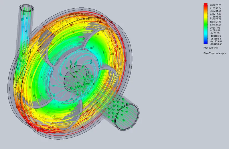
From the pressure trajectories low pressure (Blue color) in the centre of impeller and high pressure (Red color) in outer edge side of the impeller. As the impeller start rotating the centre of the impeller is low pressure vaccum created and it such the lnlet water into impeller. After some impeller rotation by the centrifugal force the pressure at the outer edge increased and it get outlet with high pressure. So, from the pressure trajectories we can say at the center of the impeller the pressure is low (30276.15 Pa or 0.3 bar) and at the outer edge of the impeller pressure is high (462773.03 or 4 bar) and water get out from the outlet.
Parametric study :
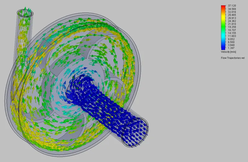
Input : Change the impeller angular velocity for [700rpm, 800rpm, 900rpm, 1000rpm]
Goals :
- Inlet total pressure
- Outlet total pressure
- Mass flow rate
- Pressure Ratio
Impeller speed - [at 700 rpm]
1) Velocity trajectories
2) Pressure trajectories

Impeller speed - [at 800 rpm]
1) Velocity trajectories
2) Pressure trajectories
Impeller speed - [at 900 rpm]
1) Velocity trajectories
2) Pressure trajectories
Impeller speed - [at 1000 rpm]
1) Velocity trajectories
2) Pressure trajectories
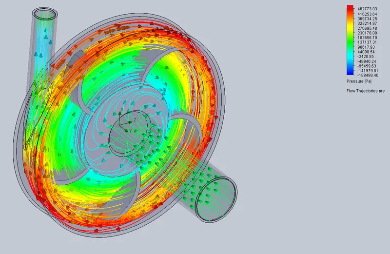
From the parametric study and its results we can say as the impeller speed increase the velocity and the pressure both are increased gradually. from the first plot 700 rpm speed the maximum flow velocity is is 26 m/s and at 1000 rpm speed the maximum velocity is 37 m/s.
Pressure ratio = outlet pressure / Inlet pressure
From the objective we run the parametric study for obtain the relationship for Mass flow rate to Pressure ratio are calculated and tabulated here,
Goal Result :

So, from the table result we can say as the Mass flow rate increase the pressure ratio also increases so these two are directly proportional to each other.
Conclusion :
Hence the centrifugal pump is designed and analysis the performance of the centrifugal pump by using the flow simulation is done successfully done in solidworks software.
From the parametric study results (pressure-velocity trajectories) we can say at the inlet and outlet side as the pressure high and the velocity low and for high velocity the pressure is low so the pressure is indirectly proportional to the velocity.
And from the parametric study (Goal results) we can say that as the pressure ratio increase the mass flow rate also increase so pressure ratio is directly proportional to the mass flow rate.